Finite Difference Method for Two-Dimensional Heat Transfer Analysis

Verified

Added on  2023/06/07

|8
|1673
|248
AI Summary
This report explains the Finite Difference Method (FDM) for analyzing two-dimensional heat transfer in a solid body. It covers the three modes of heat transfer, boundary conditions, and numerical solution methods. The problem statement is solved using iterative methods in an excel workbook. The temperature distribution is plotted for different coefficients of convective heat transfer and thermal conductivities. The report concludes with references for further reading.

Contribute Materials

Your contribution can guide someone’s learning journey. Share your documents today.
Document Page
1
Heat Transfer Assignment

Secure Best Marks with AI Grader

Need help grading? Try our AI Grader for instant feedback on your assignments.
Document Page
2
Introduction
Heat transfer can be defined as an amount of energy in transit due to temperature
difference, between two local points. Heat usually flows naturally from a high temperature
region to a low temperature region. Heat can be transferred through three modes i.e. conduction,
convection and radiation. When a boundary is perfectly insulated, then there is no transfer of
heat across the wall an adiabatic condition; such a process is mainly found in compressors,
turbines and boilers for heat insulation. In the design of energy utilities in which there is to some
extent transfer of heat, there is a need to do an analysis of the distribution of heat through the
material or thermal changes caused by external temperature variations. This report presents one
of the common numerical methods used on the analysis of such distributions. The Finite
Difference Method (FDM) is a numerical solution method in which a large body is divided into
small discrete shapes which are used to compute the physical properties of the whole body. It
uses backward, forward and central differencing schemes to analyze the differential equations.
In this problem temperature distributions are computed at the nodes of each square while
considering the boundary conditions. Both Fourier’s law of heat conduction and Newton’s law of
cooling are used to determine the nodal temperatures. For a steady state heat flow, the heat
equation becomes:
2 T
x2 + 2 T
y2 =0 . ( i )
The nodal temperature at node i , jis given by
T i , j =T i+1 , j +T i1 , j +T i , j +1 +Ti , j1
4 (ii)
The boundary conditions on the body may be subjected to a heat flux q ( W /m2 ) ,a convective heat
transfer with a coefficient of h ( W /m2 . K )and ambient temperature T ( K )or the boundary can be
considered insulated. Such are analyzed as shown below
Element subjected to a heat flux along xaxis
T i , j = q x
2 k + (T i , j+1 +2 Ti1 , j +Ti , j1
4 ) (iii)
Document Page
3
Where xis the length of the squares making up the body while k ( W /m . K )is the thermal
conductivity of the solid body.
Element’s wall is perfectly insulated
T i , j =T i , j+1 +2 Ti1 , j +Ti , j1
4 ( iv )
Element subjected to convective heat transfer at the boundary
T i , j =
h x
2 k T + T i , j+1 +2 Ti1 , j +T i, j1
2
2+ h x
2 k
.(v )
Problem statement
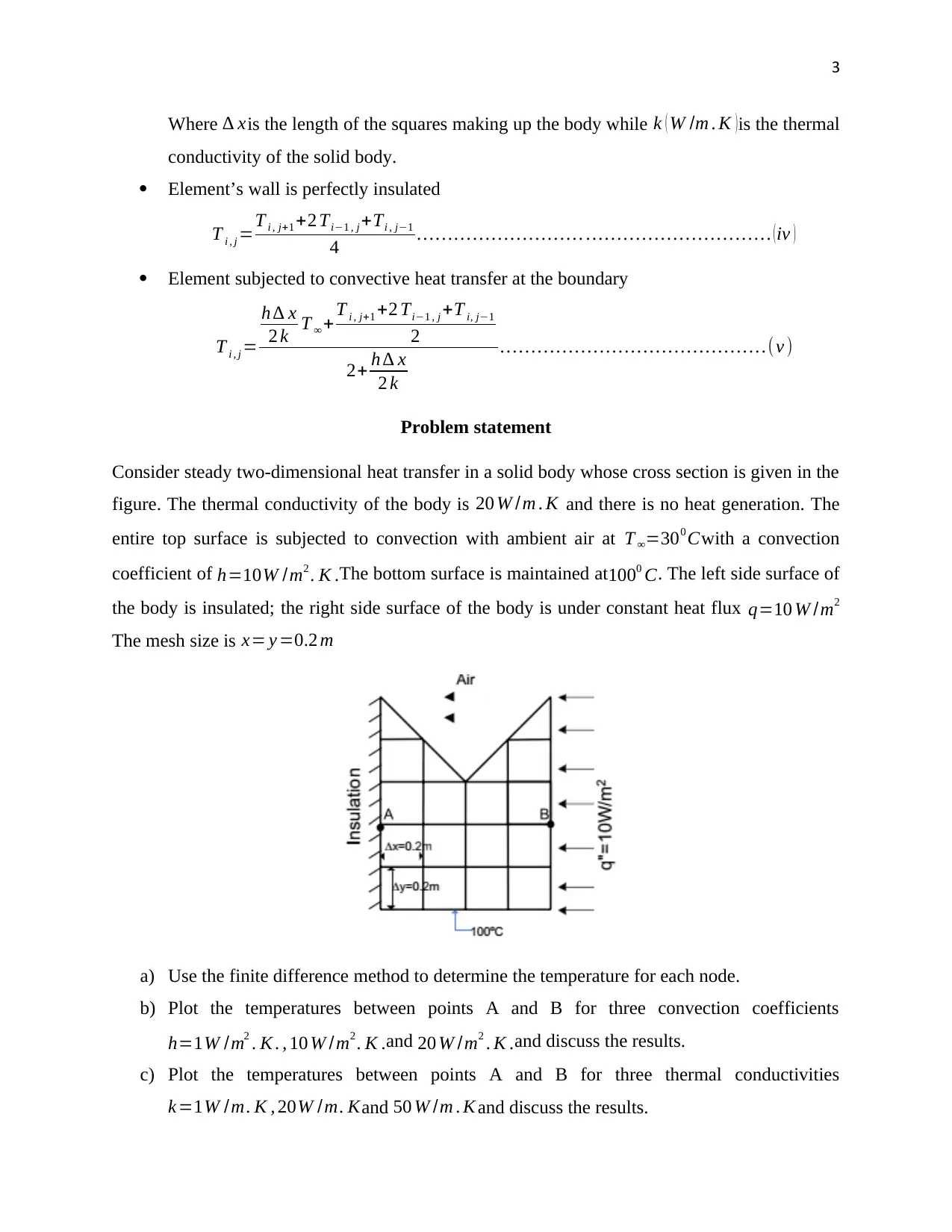
Consider steady two-dimensional heat transfer in a solid body whose cross section is given in the
figure. The thermal conductivity of the body is 20 W /m . K and there is no heat generation. The
entire top surface is subjected to convection with ambient air at T =300 Cwith a convection
coefficient of h=10W /m2 . K .The bottom surface is maintained at 1000 C. The left side surface of
the body is insulated; the right side surface of the body is under constant heat flux q=10 W /m2
The mesh size is x= y =0.2 m
a) Use the finite difference method to determine the temperature for each node.
b) Plot the temperatures between points A and B for three convection coefficients
h=1W /m2 . K . , 10 W /m2 . K .and 20 W /m2 . K .and discuss the results.
c) Plot the temperatures between points A and B for three thermal conductivities
k =1W /m. K , 20W /m. Kand 50 W /m . K and discuss the results.
Document Page
4
Calculations and Discussions
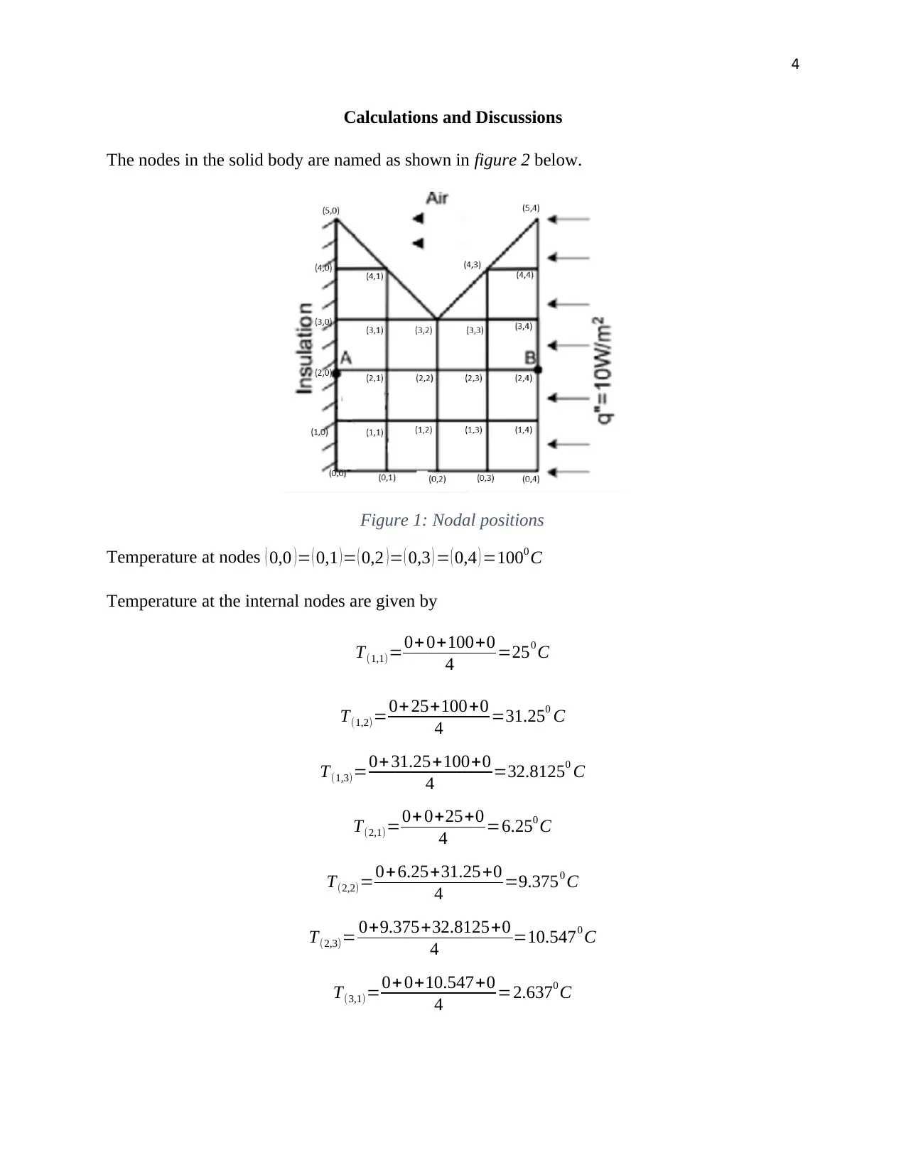
The nodes in the solid body are named as shown in figure 2 below.
Figure 1: Nodal positions
Temperature at nodes ( 0,0 )= ( 0,1 )= ( 0,2 )= ( 0,3 ) = ( 0,4 ) =1000 C
Temperature at the internal nodes are given by
T(1,1)=0+ 0+100+0
4 =250 C
T(1,2)=0+ 25+100+0
4 =31.250 C
T(1,3)=0+ 31.25+100+0
4 =32.81250 C
T(2,1)=0+ 0+25+0
4 =6.250 C
T(2,2)=0+6.25+31.25+0
4 =9.3750 C
T(2,3)= 0+9.375+32.8125+0
4 =10.5470 C
T(3,1)=0+0+10.547+0
4 =2.6370 C

Secure Best Marks with AI Grader

Need help grading? Try our AI Grader for instant feedback on your assignments.
Document Page
5
T(3,3)=0+0+10.547+0
4 =2.6370 C
Considering the left hand boundary (insulated boundary), the temperature at the nodes is given
by equation (iv) hence
T(1,0)=(2× 25)+ 0+100
4 =37.50 C
T(2,0)=(2 ×6.25)+ 0+37.5
4 =12.50 C
T(3,0)=(2× 2.637)+0+12.5
4 =4.44350 C
T(4,0)=(2 ×0)+0+ 4.4435
4 =1.11090 C
Considering the heat flux, the temperature at the nodes is obtained through equation (iii)
T(1,4)=(2 ×2.637)+0+100
4 =26.3190 C
T(2,4)=(2 ×10.547)+0+26.319
4 =11.8530 C
T(3,4)=(2 ×2.637)+0+11.853
4 =4.2120 C
T(4,4)=(2 × 0)+0+4.212
4 =1.07040 C
Considering the convective heat transfer the temperature at the nodes are
T 4,1=
10 × 0.2× 30
2× 20 + 2.637+2 ×1.1109+ 0
2
2+ 10 × 0.2
2× 20
=1.91670 C
T 4,3=
10× 0.2× 30
2× 20 + 2.637+ 2×1.0704 +0
2
2+ 10 ×0.2
2× 20
=1.89700 C
Document Page
6
T 3,2=
10 × 0.2×30
20 + 2.637+2 ×9.375+2.637
2
2+10 × 0.2
20
=7.1490 C
T 5,0=
10 × 0.2× 30
4 ×20 + 0+2 ×1.1109+0
2
2+10 × 0.2
4 × 20
=0.9190 C
T 5,4=
10× 0.2× 30
4 ×20 + 0+2×1.0704 +0
2
2+ 10 ×0.2
4 ×20
=0.8990 C
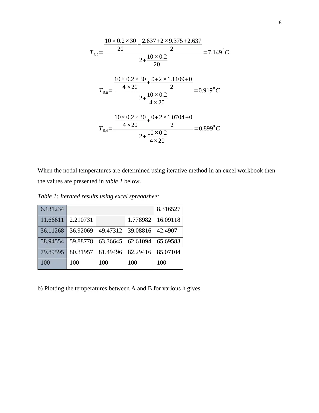
When the nodal temperatures are determined using iterative method in an excel workbook then
the values are presented in table 1 below.
Table 1: Iterated results using excel spreadsheet
6.131234 8.316527
11.66611 2.210731 1.778982 16.09118
36.11268 36.92069 49.47312 39.08816 42.4907
58.94554 59.88778 63.36645 62.61094 65.69583
79.89595 80.31957 81.49496 82.29416 85.07104
100 100 100 100 100
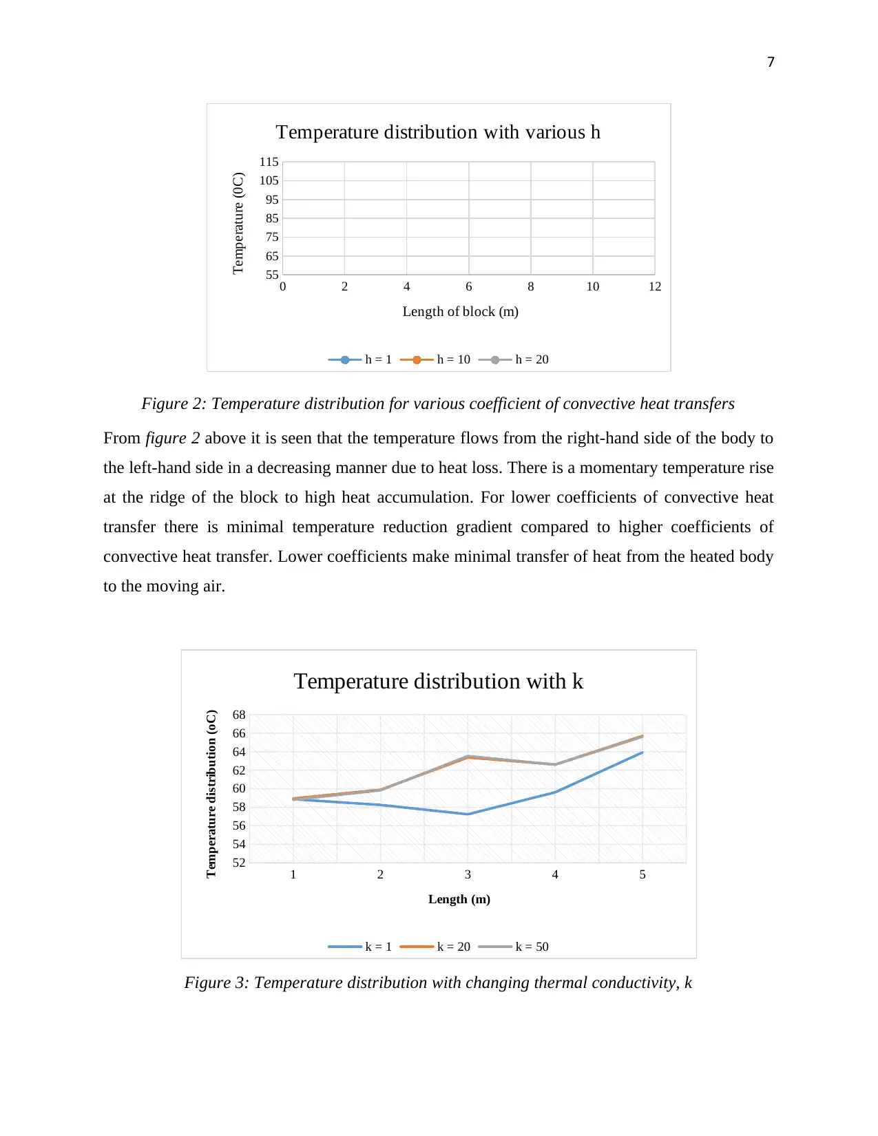
b) Plotting the temperatures between A and B for various h gives
Document Page
7
0 2 4 6 8 10 12
55
65
75
85
95
105
115
Temperature distribution with various h
h = 1 h = 10 h = 20
Length of block (m)
Temperature (0C)
Figure 2: Temperature distribution for various coefficient of convective heat transfers
From figure 2 above it is seen that the temperature flows from the right-hand side of the body to
the left-hand side in a decreasing manner due to heat loss. There is a momentary temperature rise
at the ridge of the block to high heat accumulation. For lower coefficients of convective heat
transfer there is minimal temperature reduction gradient compared to higher coefficients of
convective heat transfer. Lower coefficients make minimal transfer of heat from the heated body
to the moving air.
1 2 3 4 5
52
54
56
58
60
62
64
66
68
Temperature distribution with k
k = 1 k = 20 k = 50
Length (m)
Temperature distribution (oC)
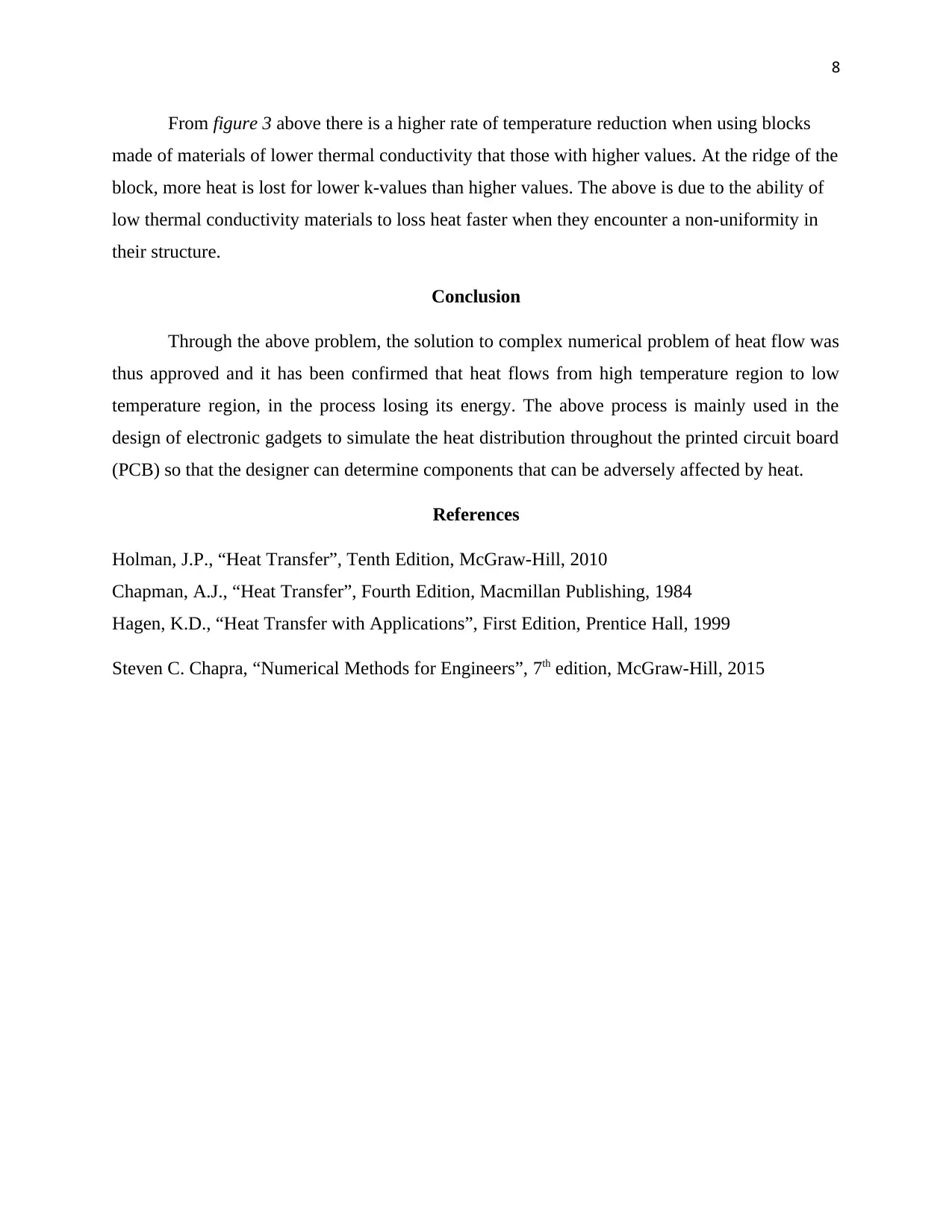
Figure 3: Temperature distribution with changing thermal conductivity, k

Paraphrase This Document

Need a fresh take? Get an instant paraphrase of this document with our AI Paraphraser
Document Page
8
From figure 3 above there is a higher rate of temperature reduction when using blocks
made of materials of lower thermal conductivity that those with higher values. At the ridge of the
block, more heat is lost for lower k-values than higher values. The above is due to the ability of
low thermal conductivity materials to loss heat faster when they encounter a non-uniformity in
their structure.
Conclusion
Through the above problem, the solution to complex numerical problem of heat flow was
thus approved and it has been confirmed that heat flows from high temperature region to low
temperature region, in the process losing its energy. The above process is mainly used in the
design of electronic gadgets to simulate the heat distribution throughout the printed circuit board
(PCB) so that the designer can determine components that can be adversely affected by heat.
References
Holman, J.P., “Heat Transfer”, Tenth Edition, McGraw-Hill, 2010
Chapman, A.J., “Heat Transfer”, Fourth Edition, Macmillan Publishing, 1984
Hagen, K.D., “Heat Transfer with Applications”, First Edition, Prentice Hall, 1999
Steven C. Chapra, “Numerical Methods for Engineers”, 7th edition, McGraw-Hill, 2015
1 out of 8
circle_padding
hide_on_mobile
zoom_out_icon
[object Object]

Your All-in-One AI-Powered Toolkit for Academic Success.

Available 24*7 on WhatsApp / Email

[object Object]