Finite Element Analysis of Flat Slab: A Structural Engineering Report
VerifiedAdded on 2023/06/14
|13
|1785
|443
Report
AI Summary
This report details a finite element analysis (FEA) performed on a flat slab using MIDAS GEN software, adhering to EC2 standards. The analysis focuses on determining the minimum slab thickness required to resist punching shear with shear reinforcement. The report includes a literature review of flat slab analysis methods, a description of the FE model creation process (including grid generation, element creation, loading, and meshing), and a presentation of the analysis results. The punching shear capacity is calculated, and recommendations are made regarding the use of drop heads to further reduce slab thickness. The report concludes with a bibliography of relevant resources.

Finite Element Analysis 1
FINITE ELEMENT ANALYSIS
By (Name)
Course
Professor’s name
University name
City, State
Date of submission
FINITE ELEMENT ANALYSIS
By (Name)
Course
Professor’s name
University name
City, State
Date of submission
Paraphrase This Document
Need a fresh take? Get an instant paraphrase of this document with our AI Paraphraser
Finite Element Analysis 2
Table of Contents
Abstract............................................................................................................................................3
Introduction......................................................................................................................................3
Literature review..............................................................................................................................5
Creating an FE model...................................................................................................................6
Design process using FEA...........................................................................................................7
Methodology....................................................................................................................................7
Job preference..............................................................................................................................7
Grid..............................................................................................................................................7
Elements creation.........................................................................................................................8
Loading........................................................................................................................................8
Analysis........................................................................................................................................9
Results..............................................................................................................................................9
Calculation.....................................................................................................................................11
Conclusions and Recommendations..............................................................................................12
Finite Element Analysis 3
Abstract
The purpose of this report is to test on the ability to use any Finite element software. The
requirement is to perform a finite element analysis and to model a flat slab. The flat slab
analyzed must be of the smallest thickness that will be able to resist punching shear with
provision of the shear reinforcement.
Introduction
The flat slab that I analyzed was of the following properties; the distances between the grids
are X1, X2, and Y1, Y2 are 6.00m, 6.00m, 6.75m, and 7.00m. the thickness 200mm. and the
supporting columns are 300mm square. The loading are the variable loads is 3 kN/m2, the
perment loads are partions load 1 kN/m2 and other is the self- weight. The wind load on the
building is taken care by the bracing. The thickness of the slab 200mm which is to the nearest
25mm and satisfy the value of the design shear resistance in the EC2without the provision of
shear reinforcement.
⊘ This is a preview!⊘
Do you want full access?
Subscribe today to unlock all pages.
Trusted by 1+ million students worldwide
Finite Element Analysis 4
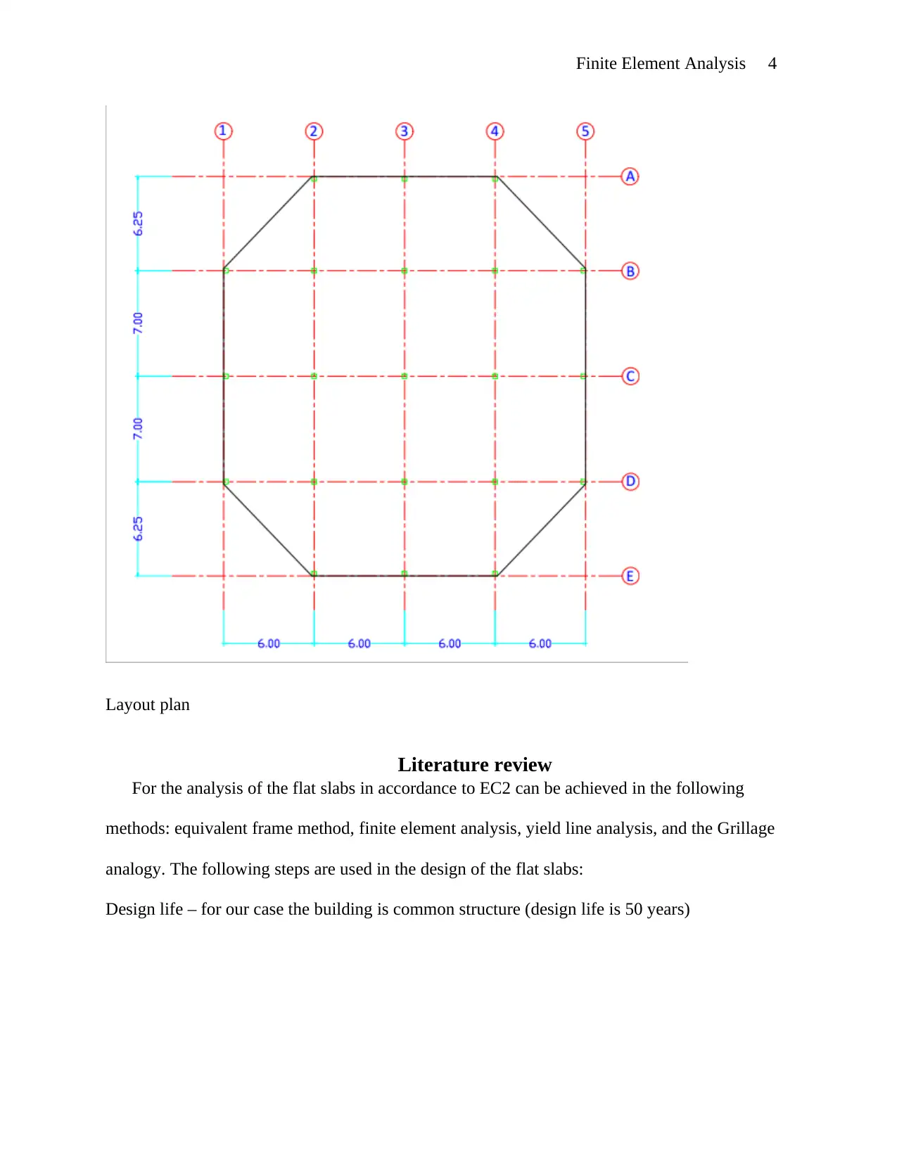
Layout plan
Literature review
For the analysis of the flat slabs in accordance to EC2 can be achieved in the following
methods: equivalent frame method, finite element analysis, yield line analysis, and the Grillage
analogy. The following steps are used in the design of the flat slabs:
Design life – for our case the building is common structure (design life is 50 years)
Paraphrase This Document
Need a fresh take? Get an instant paraphrase of this document with our AI Paraphraser
Finite Element Analysis 5
Asses of the loading on the slab. in this case the ratio of the variable loads to permanent loads
should be less than 1.25
1. Determine the load combination applied.in our case we considered the variable loads and
permanent loads, since the assumption made is that the wind load is taken care by the
bracing.
2. Determine loading arrangements. The 1.35Qk+1.5Gk (ULS) and 1.0 (Qk+Gk) for SLS.
3. Assess durability requirements and determine the concrete strength. In our case the grade
of the concrete used is C40/50.
4. Fire resistance period check. Here we provide suitable cover for the fire resistance period.
Provided 25mm cover
5. Determine the minimum cover for durability, fire and bond requirements. Best choice
25mm cover both ways.
6. Analyze structure to obtain critical moments (Mc)and shear forces (Vc).
7. Design flexural reinforcement
8. Check defection.
9. Check punching shear capacity
10. Check spacing of the bars
Finite element analysis is the use of the ordinary or partial differential equation by a
computer to solve wide range of structural problems. The FEA software in our case Midas Gen
has the following features applicable that assist in the analysis of the structure, flat slab:
Finite Element Analysis 6
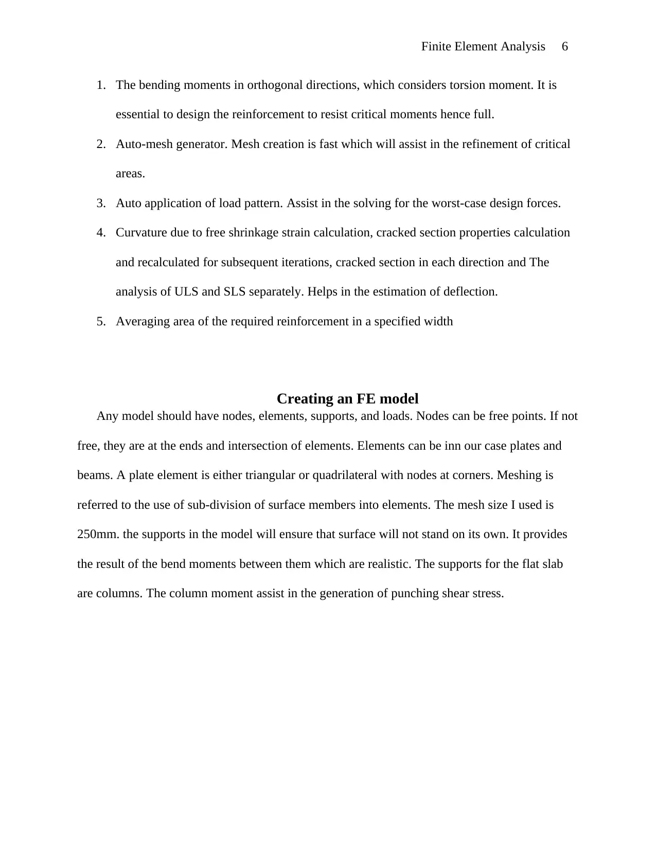
1. The bending moments in orthogonal directions, which considers torsion moment. It is
essential to design the reinforcement to resist critical moments hence full.
2. Auto-mesh generator. Mesh creation is fast which will assist in the refinement of critical
areas.
3. Auto application of load pattern. Assist in the solving for the worst-case design forces.
4. Curvature due to free shrinkage strain calculation, cracked section properties calculation
and recalculated for subsequent iterations, cracked section in each direction and The
analysis of ULS and SLS separately. Helps in the estimation of deflection.
5. Averaging area of the required reinforcement in a specified width
Creating an FE model
Any model should have nodes, elements, supports, and loads. Nodes can be free points. If not
free, they are at the ends and intersection of elements. Elements can be inn our case plates and
beams. A plate element is either triangular or quadrilateral with nodes at corners. Meshing is
referred to the use of sub-division of surface members into elements. The mesh size I used is
250mm. the supports in the model will ensure that surface will not stand on its own. It provides
the result of the bend moments between them which are realistic. The supports for the flat slab
are columns. The column moment assist in the generation of punching shear stress.
⊘ This is a preview!⊘
Do you want full access?
Subscribe today to unlock all pages.
Trusted by 1+ million students worldwide
Finite Element Analysis 7
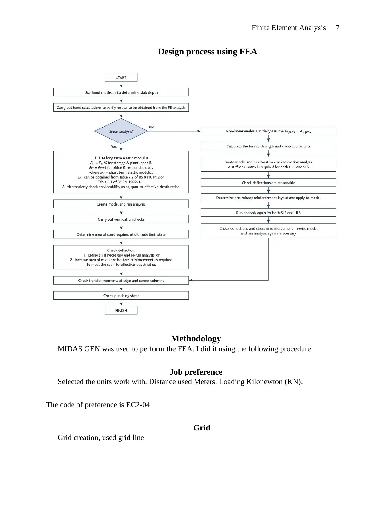
Design process using FEA
Methodology
MIDAS GEN was used to perform the FEA. I did it using the following procedure
Job preference
Selected the units work with. Distance used Meters. Loading Kilonewton (KN).
The code of preference is EC2-04
Grid
Grid creation, used grid line
Design process using FEA
Methodology
MIDAS GEN was used to perform the FEA. I did it using the following procedure
Job preference
Selected the units work with. Distance used Meters. Loading Kilonewton (KN).
The code of preference is EC2-04
Grid
Grid creation, used grid line
Paraphrase This Document
Need a fresh take? Get an instant paraphrase of this document with our AI Paraphraser
Finite Element Analysis 8
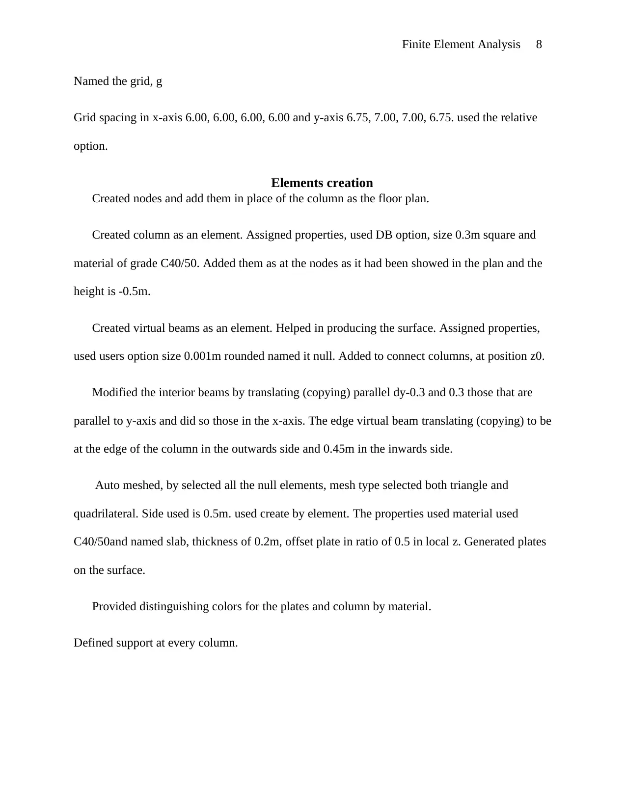
Named the grid, g
Grid spacing in x-axis 6.00, 6.00, 6.00, 6.00 and y-axis 6.75, 7.00, 7.00, 6.75. used the relative
option.
Elements creation
Created nodes and add them in place of the column as the floor plan.
Created column as an element. Assigned properties, used DB option, size 0.3m square and
material of grade C40/50. Added them as at the nodes as it had been showed in the plan and the
height is -0.5m.
Created virtual beams as an element. Helped in producing the surface. Assigned properties,
used users option size 0.001m rounded named it null. Added to connect columns, at position z0.
Modified the interior beams by translating (copying) parallel dy-0.3 and 0.3 those that are
parallel to y-axis and did so those in the x-axis. The edge virtual beam translating (copying) to be
at the edge of the column in the outwards side and 0.45m in the inwards side.
Auto meshed, by selected all the null elements, mesh type selected both triangle and
quadrilateral. Side used is 0.5m. used create by element. The properties used material used
C40/50and named slab, thickness of 0.2m, offset plate in ratio of 0.5 in local z. Generated plates
on the surface.
Provided distinguishing colors for the plates and column by material.
Defined support at every column.
Finite Element Analysis 9
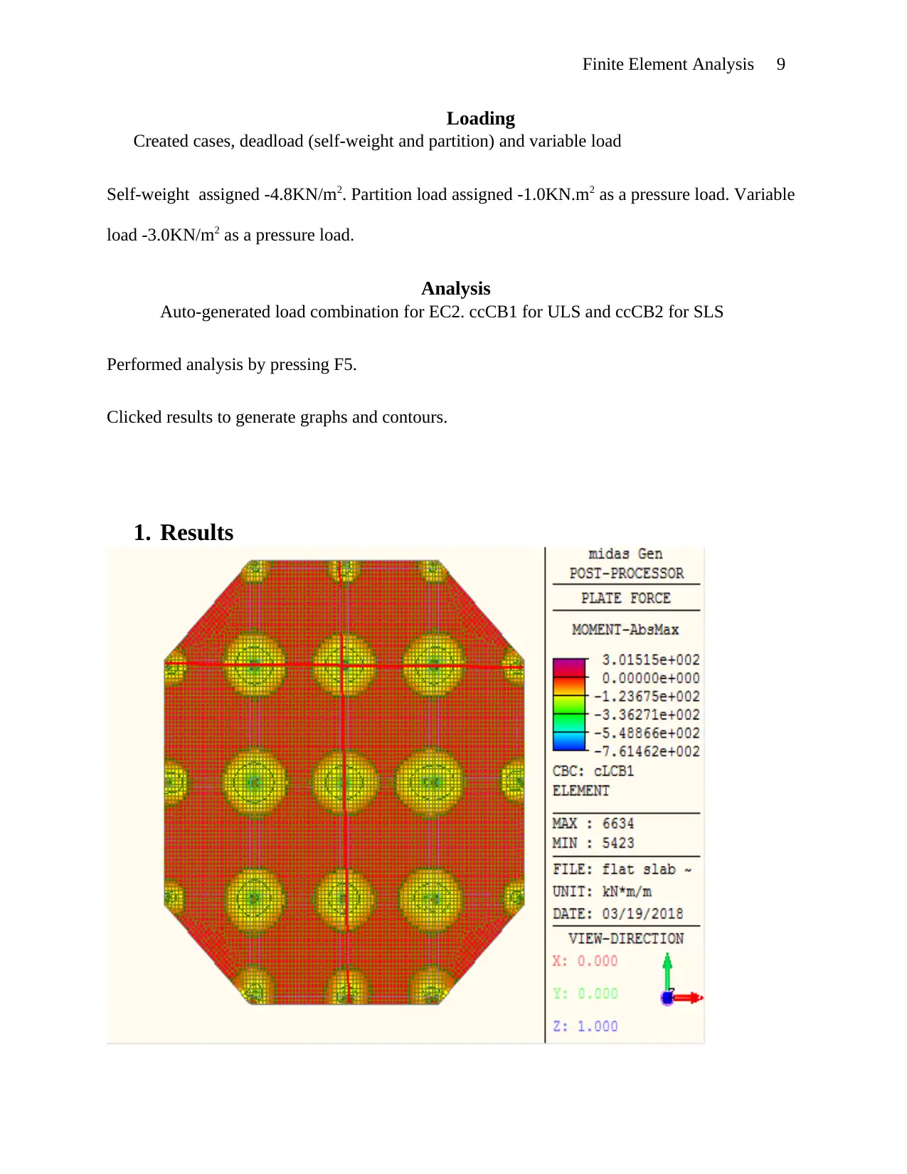
Loading
Created cases, deadload (self-weight and partition) and variable load
Self-weight assigned -4.8KN/m2. Partition load assigned -1.0KN.m2 as a pressure load. Variable
load -3.0KN/m2 as a pressure load.
Analysis
Auto-generated load combination for EC2. ccCB1 for ULS and ccCB2 for SLS
Performed analysis by pressing F5.
Clicked results to generate graphs and contours.
1. Results
⊘ This is a preview!⊘
Do you want full access?
Subscribe today to unlock all pages.
Trusted by 1+ million students worldwide
Finite Element Analysis 10
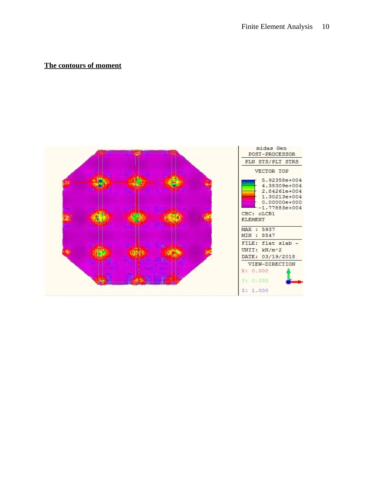
The contours of moment
The contours of moment
Paraphrase This Document
Need a fresh take? Get an instant paraphrase of this document with our AI Paraphraser
Finite Element Analysis 11
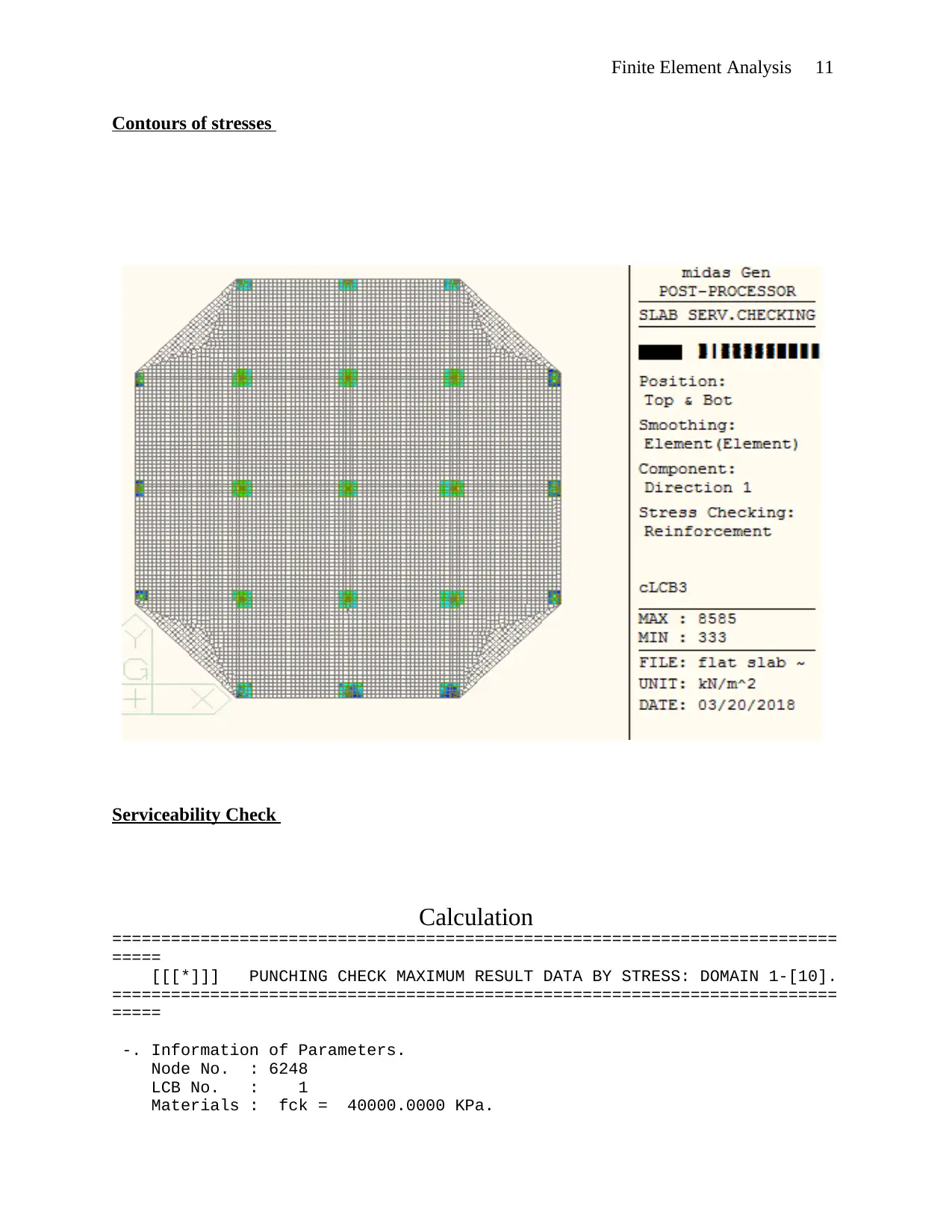
Contours of stresses
Serviceability Check
Calculation
==========================================================================
=====
[[[*]]] PUNCHING CHECK MAXIMUM RESULT DATA BY STRESS: DOMAIN 1-[10].
==========================================================================
=====
-. Information of Parameters.
Node No. : 6248
LCB No. : 1
Materials : fck = 40000.0000 KPa.
Finite Element Analysis 12
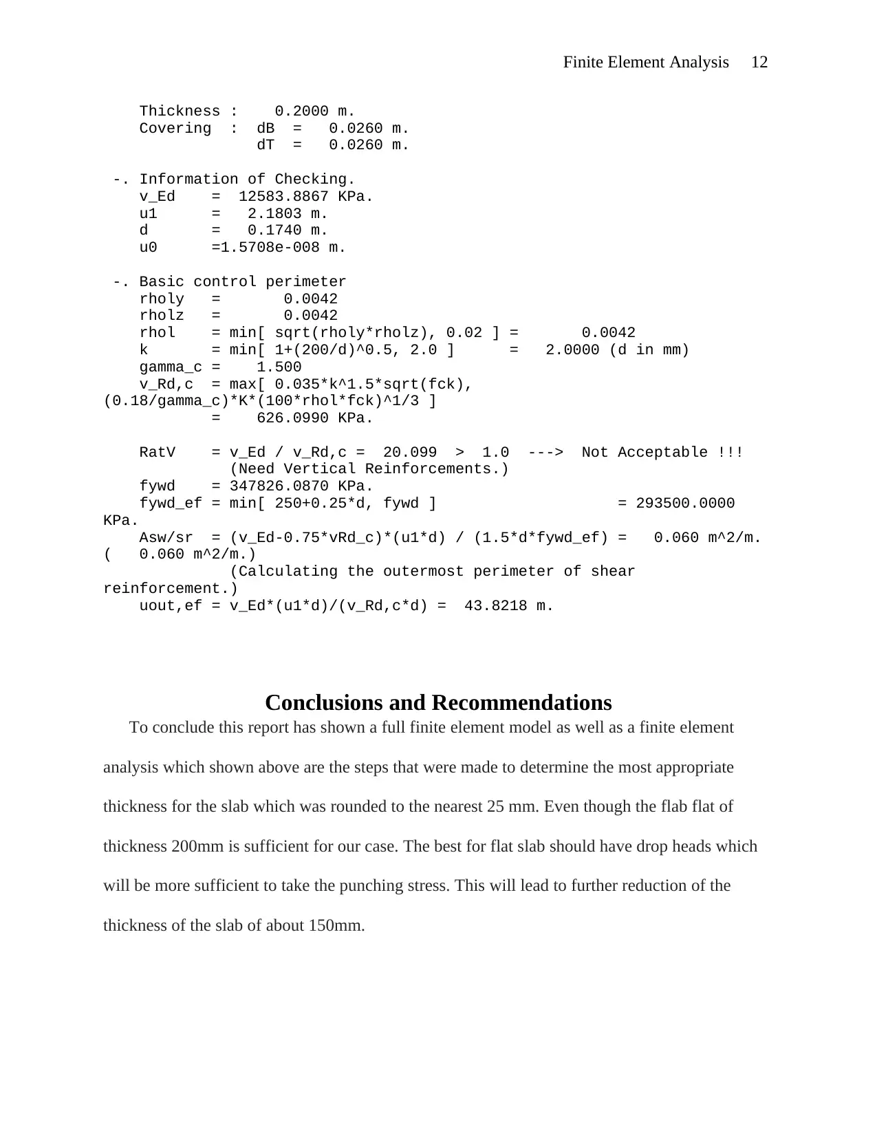
Thickness : 0.2000 m.
Covering : dB = 0.0260 m.
dT = 0.0260 m.
-. Information of Checking.
v_Ed = 12583.8867 KPa.
u1 = 2.1803 m.
d = 0.1740 m.
u0 =1.5708e-008 m.
-. Basic control perimeter
rholy = 0.0042
rholz = 0.0042
rhol = min[ sqrt(rholy*rholz), 0.02 ] = 0.0042
k = min[ 1+(200/d)^0.5, 2.0 ] = 2.0000 (d in mm)
gamma_c = 1.500
v_Rd,c = max[ 0.035*k^1.5*sqrt(fck),
(0.18/gamma_c)*K*(100*rhol*fck)^1/3 ]
= 626.0990 KPa.
RatV = v_Ed / v_Rd,c = 20.099 > 1.0 ---> Not Acceptable !!!
(Need Vertical Reinforcements.)
fywd = 347826.0870 KPa.
fywd_ef = min[ 250+0.25*d, fywd ] = 293500.0000
KPa.
Asw/sr = (v_Ed-0.75*vRd_c)*(u1*d) / (1.5*d*fywd_ef) = 0.060 m^2/m.
( 0.060 m^2/m.)
(Calculating the outermost perimeter of shear
reinforcement.)
uout,ef = v_Ed*(u1*d)/(v_Rd,c*d) = 43.8218 m.
Conclusions and Recommendations
To conclude this report has shown a full finite element model as well as a finite element
analysis which shown above are the steps that were made to determine the most appropriate
thickness for the slab which was rounded to the nearest 25 mm. Even though the flab flat of
thickness 200mm is sufficient for our case. The best for flat slab should have drop heads which
will be more sufficient to take the punching stress. This will lead to further reduction of the
thickness of the slab of about 150mm.
⊘ This is a preview!⊘
Do you want full access?
Subscribe today to unlock all pages.
Trusted by 1+ million students worldwide
1 out of 13

Your All-in-One AI-Powered Toolkit for Academic Success.
+13062052269
info@desklib.com
Available 24*7 on WhatsApp / Email
![[object Object]](/_next/static/media/star-bottom.7253800d.svg)
Unlock your academic potential
Copyright © 2020–2025 A2Z Services. All Rights Reserved. Developed and managed by ZUCOL.