logo

Finite Element Method (Part 1) EG55M1 Assignment 1 - University of Aberdeen

11 Pages1996 Words124 Views
   

University of Aberdeen


Finite Element Method (EG55M1)


Added on  2023-04-24

About This Document

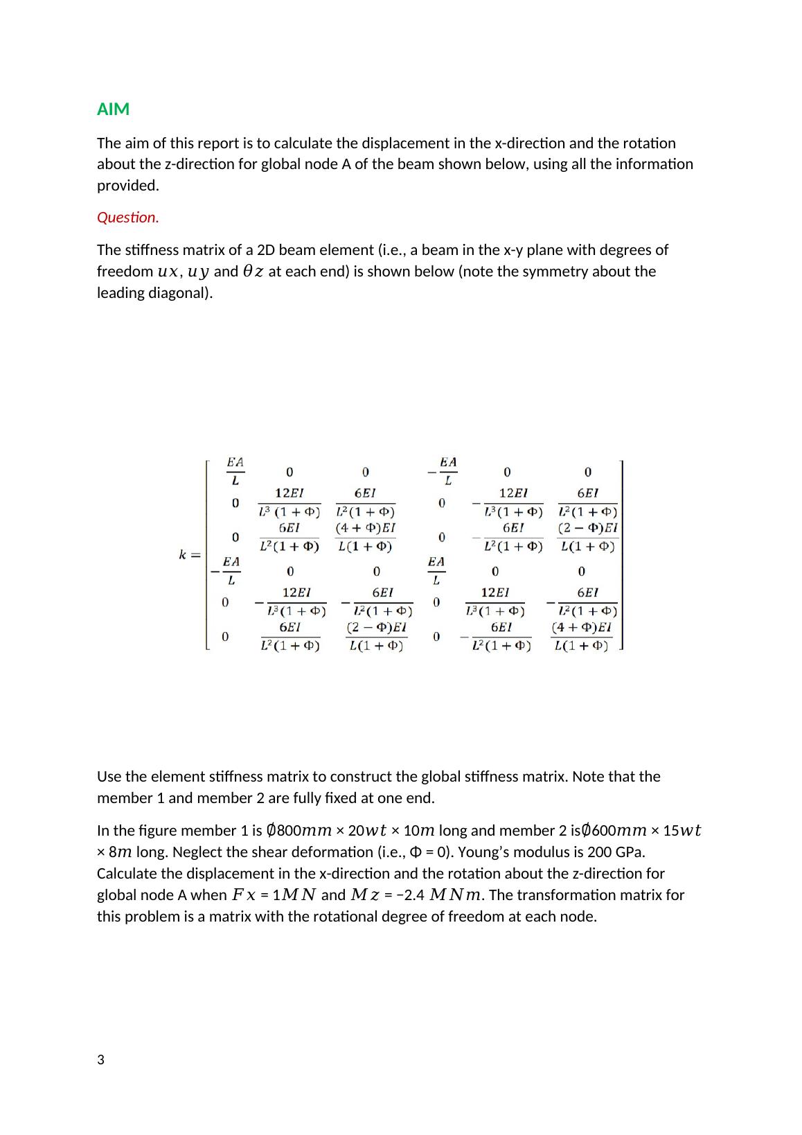
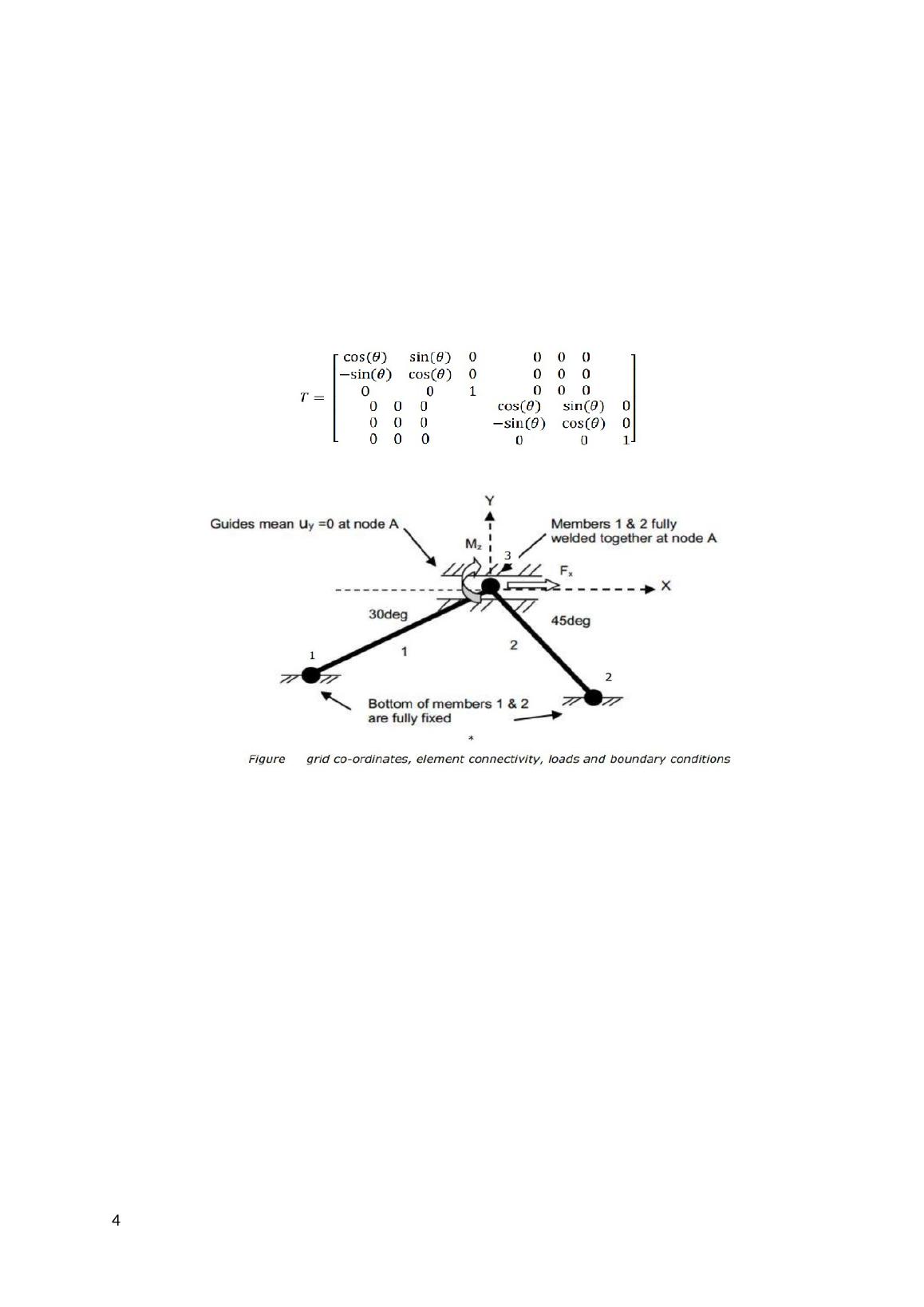
  • The aim of the report is to calculate the displacement in the x-direction and rotation about the z-direction for global node A of the beam.
  • The problem is solved using finite element method with the given stiffness matrix and properties of the elements.

Finite Element Method (Part 1) EG55M1 Assignment 1 - University of Aberdeen


University of Aberdeen


Finite Element Method (EG55M1)

   Added on 2023-04-24

ShareRelated Documents
Finite Element Method (Part 1)
EG55M1
Assignment One
Completed by Group 1
Group Members
ADELEKE OLUGBENGA
GANGADHARAN NAMITA
MINHAJ MD HABIBULLAH
Finite Element Method (Part 1) EG55M1 Assignment 1 - University of Aberdeen_1
INTRODUCTION
Finite Element Method is a numerical method used to analyse complex engineering
structures and systems. This is achieved by partitioning the structure into smaller simpler
parts or elements. This method gives approximation solutions to physical problems.
Using finite element analysis method, we can determine the stress, strain and deformation
in the structure. In this problem the type of finite element analysis systems used is linear
static structural capabilities which is a beam in the x-y plane with degrees of freedom 𝑢𝑥,
𝑢𝑦 and 𝜃𝑧 at each end.
The element properties are given, which are then used to construct global properties, and
after the boundary conditions are imposed, then the displacement in the x-direction and the
rotation about the z-direction are calculated.
These are the steps required to solve the problem using finite element method.
Discretisation
Determination of the local element characteristics
Transformation of the element characteristics
Assembly of the global element characteristics
Application of the boundary conditions
Determination of the unknowns from the finite element equation
2
Finite Element Method (Part 1) EG55M1 Assignment 1 - University of Aberdeen_2
AIM
The aim of this report is to calculate the displacement in the x-direction and the rotation
about the z-direction for global node A of the beam shown below, using all the information
provided.
Question.
The stiffness matrix of a 2D beam element (i.e., a beam in the x-y plane with degrees of
freedom 𝑢𝑥, 𝑢𝑦 and 𝜃𝑧 at each end) is shown below (note the symmetry about the
leading diagonal).
Use the element stiffness matrix to construct the global stiffness matrix. Note that the
member 1 and member 2 are fully fixed at one end.
In the figure member 1 is 800𝑚𝑚 × 20𝑤𝑡 × 10𝑚 long and member 2 is600𝑚𝑚 × 15𝑤𝑡
× 8𝑚 long. Neglect the shear deformation (i.e., Φ = 0). Young’s modulus is 200 GPa.
Calculate the displacement in the x-direction and the rotation about the z-direction for
global node A when 𝐹𝑥 = 1𝑀𝑁 and 𝑀𝑧 = −2.4 𝑀𝑁𝑚. The transformation matrix for
this problem is a matrix with the rotational degree of freedom at each node.
3
Finite Element Method (Part 1) EG55M1 Assignment 1 - University of Aberdeen_3
4
Finite Element Method (Part 1) EG55M1 Assignment 1 - University of Aberdeen_4

End of preview

Want to access all the pages? Upload your documents or become a member.

Related Documents
Answer (2). Given data:. Stress at point (A). Internal
|10
|467
|172