Flexural Beams Lab Report: Structural Engineering 1, University Report
VerifiedAdded on 2023/06/03
|13
|1701
|338
Report
AI Summary
This lab report presents an analysis of the flexural behavior of beams, focusing on experiments conducted on timber, steel, and reinforced concrete (RC) beams. The objective was to determine flexural strength, flexural modulus, and maximum flexural strain. The report outlines the experimental setup, which involved a four-point bending test, and details the procedure including the measurement of beam dimensions, setup of the loading block, and application of loads until failure. The results section presents observations on failure modes, such as shear flexure and ductile flexural failure, as well as the elastic and plastic limits of the materials. The conclusion summarizes the findings, highlighting experimental errors and their potential causes related to material handling. The report also includes a comprehensive list of references.
Flexural Beams Lab Report 1
Flexural Beams Lab Report
by Student’s Name
Code + Course Name
Professor’s Name
University Name
City, State
Date
Flexural Beams Lab Report
by Student’s Name
Code + Course Name
Professor’s Name
University Name
City, State
Date
Paraphrase This Document
Need a fresh take? Get an instant paraphrase of this document with our AI Paraphraser
Flexural Beams Lab Report 2
Flexural Beams Lab Report
Objective
The primary objective of this study is to determine the overall value of flexural strength, flexural
modulus as well as the maximum flexural strain of the material. This analysis mainly appraises at
least five beams and these includes 2 timber beams 2 reinforced concrete (RC) beams as well
as 1 steel beam.
Introduction
In essence, this mechanical lab work mainly used to measure and determine the materials
behaviors when they subjected to the parametric bending loads. Flexural modulus or stiffness of
the material mainly computed from the being load against deflection curve slope. Furthermore, it
is important to note that flexural bending mainly incorporates the material bending rather than
just focusing on the pulling and pushing impacts (Kang et al. 2014). This is often used in
computing the existing relationship between the overall deflection and the bending in the
material. Additionally, it is essential to establish and report that flexural testing mainly used to
handle the brittle materials and some of these primarily include stones, masonry, glasses as well
as ceramics. Subsequently, the concept of the makeable three points mainly used in developing
the bending flexural test and they help in providing the elasticity modulus in line with the
flexural bending, strain as well as stress. In essence, the three pint method tends to have
advantages more so when one is dealing with the specimen preparations as well as the testing.
Conversely, the method main have imminent disadvantages when one is dealing with it. The
disadvantages mainly include sensitive recorded on the loading geometry and the specimen stain
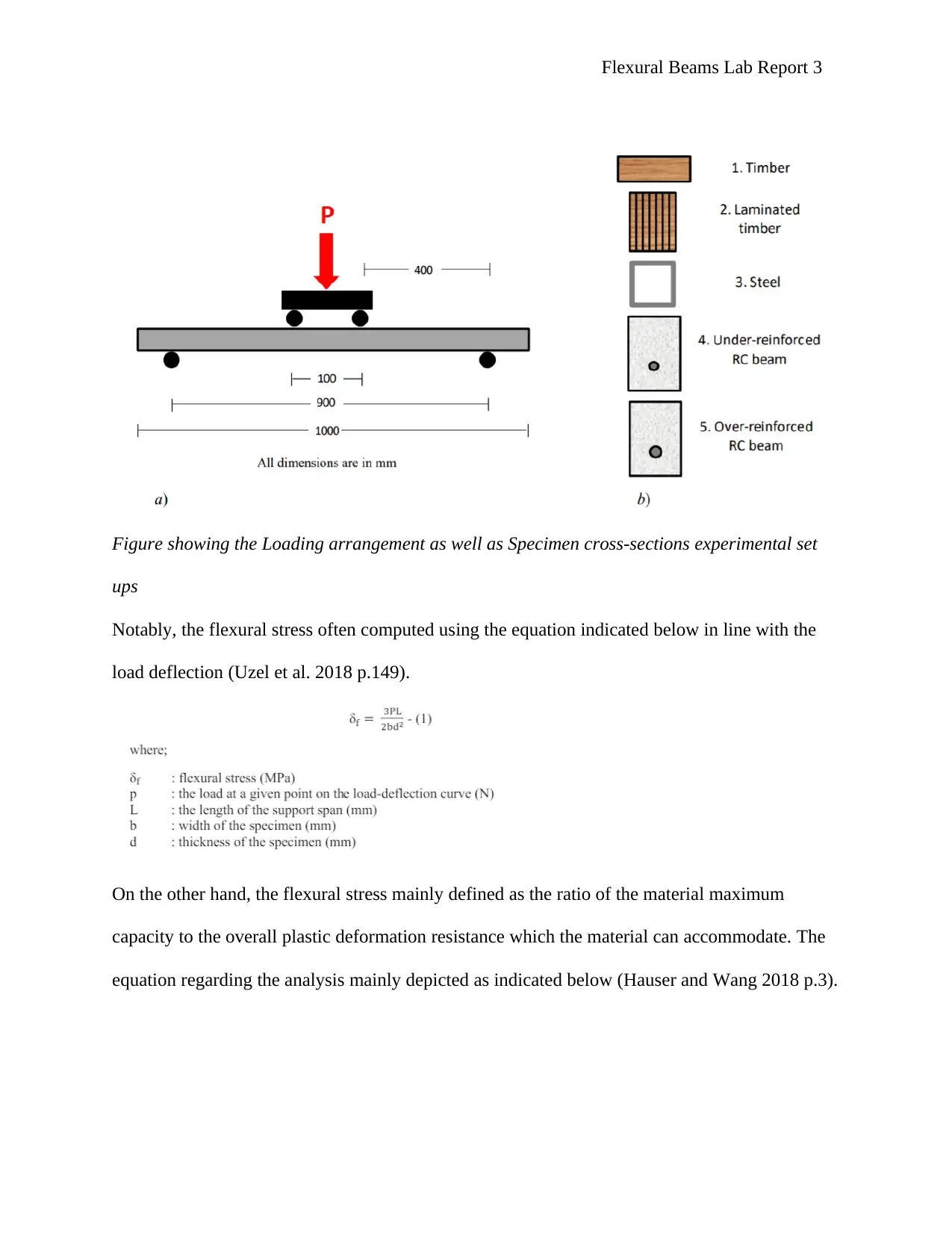
rate. The analysis for the three point testing method mainly illustrated as shown in the figure
below (Disfani et al. 2014 p.667).
Flexural Beams Lab Report 3
Figure showing the Loading arrangement as well as Specimen cross-sections experimental set
ups
Notably, the flexural stress often computed using the equation indicated below in line with the
load deflection (Uzel et al. 2018 p.149).
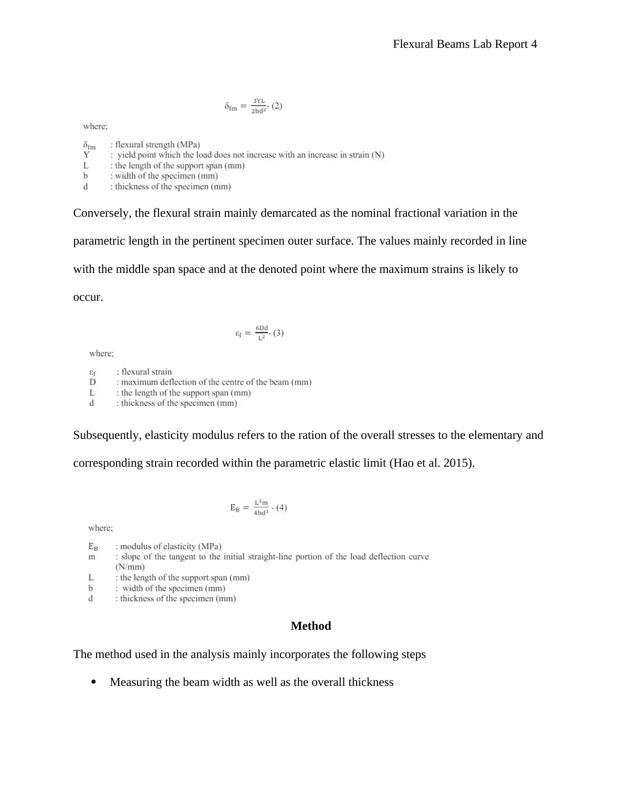
On the other hand, the flexural stress mainly defined as the ratio of the material maximum
capacity to the overall plastic deformation resistance which the material can accommodate. The
equation regarding the analysis mainly depicted as indicated below (Hauser and Wang 2018 p.3).
⊘ This is a preview!⊘
Do you want full access?
Subscribe today to unlock all pages.

Trusted by 1+ million students worldwide
Flexural Beams Lab Report 4
Conversely, the flexural strain mainly demarcated as the nominal fractional variation in the
parametric length in the pertinent specimen outer surface. The values mainly recorded in line
with the middle span space and at the denoted point where the maximum strains is likely to
occur.
Subsequently, elasticity modulus refers to the ration of the overall stresses to the elementary and
corresponding strain recorded within the parametric elastic limit (Hao et al. 2015).
Method
The method used in the analysis mainly incorporates the following steps
Measuring the beam width as well as the overall thickness
Paraphrase This Document
Need a fresh take? Get an instant paraphrase of this document with our AI Paraphraser
Flexural Beams Lab Report 5
Gripping the loading block as well as testing the jig in the overall lower and upper
gripping head decisively.
Furthermore, locate the specimen in the makeable manner that it is in the upper surface
and located at the elementary side at the designated center in line with the loading
assembly (Chidambaram and Agarwal 2015 p.271).
Thereafter operate the machine and this must be conducted until the parametric loading
block depicts the makeable contact with the specimen upper surfaces. Notably, it is
important to have a full contact existing between the specimen and the load as well as the
support section (Leclère, Ablitzer and Pézerat 2015 p.106).
Also, set all the required parameters at the designated control panel
Moreover, adjust the load recorded to accommodate the load applied. This has to set at
various levels which include panel controller and the level of the load application point
Once all the set aspects have been worked on, then it is the moment to press the start
button. This is conducted to start the overall flexural test.
In the process, it is important to observe the specimen more so as the load often applied
to the system gradually (Marí 2015 p.1399).
Finally, record the overall maximum load. However, it is important to carry on the
process of the loading in the material until the overall failure depicted in the system.
Thus, record the results obtained from the experiment in the parametric table.
Results and Discussion
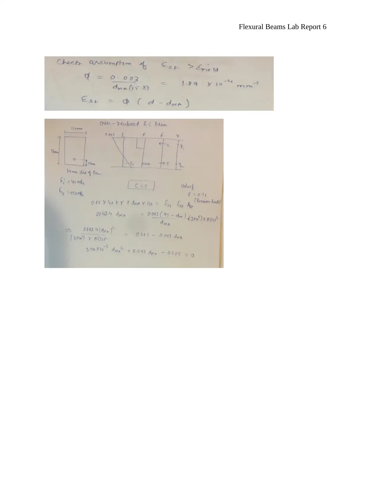
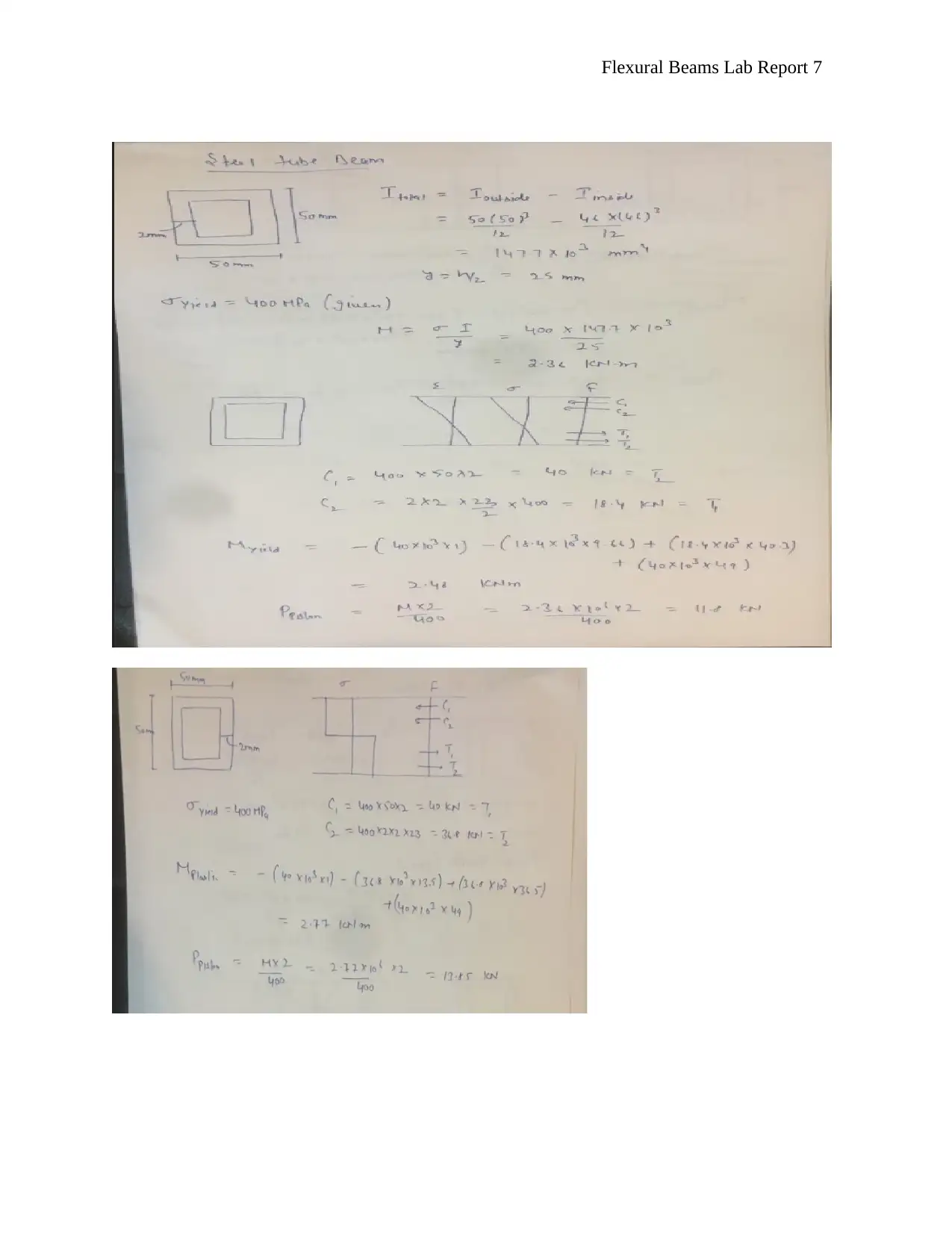
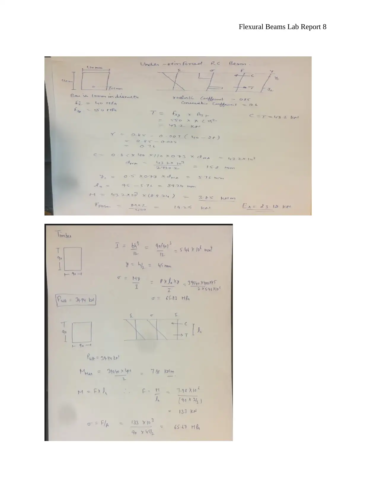
The results obtained from the overall process mainly recorded as indicated in the analysis below
(Kassem 2018).
Flexural Beams Lab Report 6
⊘ This is a preview!⊘
Do you want full access?
Subscribe today to unlock all pages.

Trusted by 1+ million students worldwide
Flexural Beams Lab Report 7
Paraphrase This Document
Need a fresh take? Get an instant paraphrase of this document with our AI Paraphraser
Flexural Beams Lab Report 8
Flexural Beams Lab Report 9
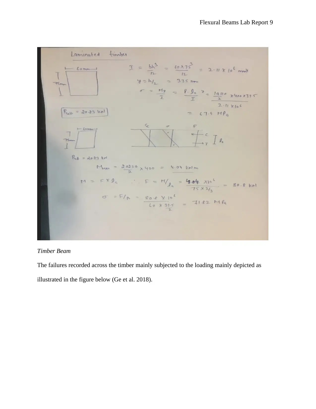
Timber Beam
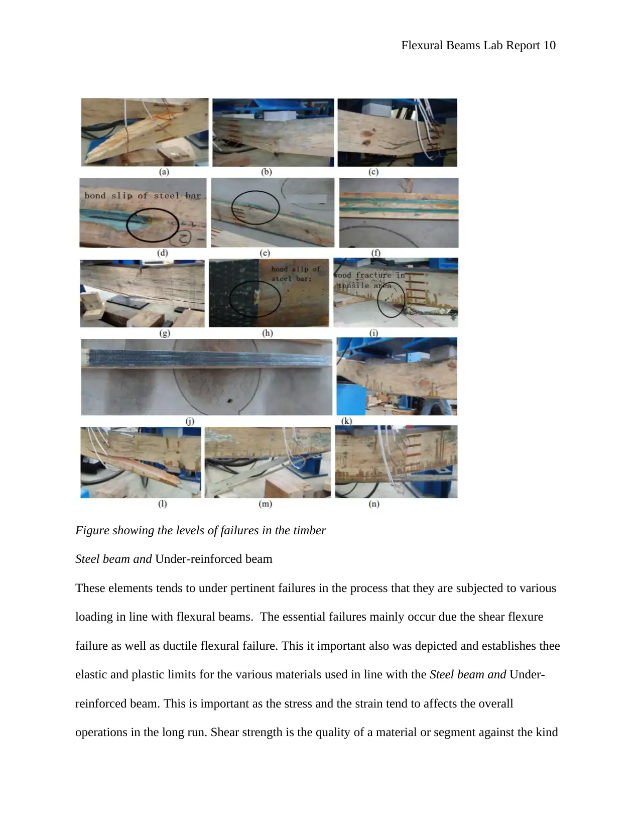
The failures recorded across the timber mainly subjected to the loading mainly depicted as
illustrated in the figure below (Ge et al. 2018).
Timber Beam
The failures recorded across the timber mainly subjected to the loading mainly depicted as
illustrated in the figure below (Ge et al. 2018).
⊘ This is a preview!⊘
Do you want full access?
Subscribe today to unlock all pages.

Trusted by 1+ million students worldwide
Flexural Beams Lab Report 10
Figure showing the levels of failures in the timber
Steel beam and Under-reinforced beam
These elements tends to under pertinent failures in the process that they are subjected to various
loading in line with flexural beams. The essential failures mainly occur due the shear flexure
failure as well as ductile flexural failure. This it important also was depicted and establishes thee
elastic and plastic limits for the various materials used in line with the Steel beam and Under-
reinforced beam. This is important as the stress and the strain tend to affects the overall
operations in the long run. Shear strength is the quality of a material or segment against the kind
Paraphrase This Document
Need a fresh take? Get an instant paraphrase of this document with our AI Paraphraser
Flexural Beams Lab Report 11
of yield or auxiliary disappointment where the material or segment bombs in shear. A shear stack
is a power that tends to create a sliding disappointment on a material along a plane that is parallel
to the course of the power.
Conclusion
In summary, it is important to note that the system functions for the various metal bending bars
in line with the varying stiffness and the parametric thickness mainly used in this analysis. In
essence, the test gives priorities to the specimens used in the process. The applied force in the
system mainly measured using the calculation system and the overall built in calibration.
Furthermore, large margin of the errors mainly recorded. The value often recorded when
appraising the value between the calculated results and the measure one. This indicates that this
experiment often not accepted in the practical context in the long run. Subsequently, the value
recorded at the maximum deflection mainly indicates that there is an experimental error of at
least value ranging from 65% to the overall 70%. However, the overall reason for the error
recorded mainly grounded on the material handling technique. In essence, the experiment mainly
meant to handle small deflections in the meantime. Thus, proper analysis need to be considered
and followed decisively so as to obtained the precise results and the values which are consistent
in the long run.
Flexural Beams Lab Report 12
References
Chidambaram, R.S. and Agarwal, P., 2015. Flexural and shear behavior of geo-grid confined RC
beams with steel fiber reinforced concrete. Construction and Building materials, 78, pp.271-280.
Disfani, M.M., Arulrajah, A., Haghighi, H., Mohammadinia, A. and Horpibulsuk, S., 2014.
Flexural beam fatigue strength evaluation of crushed brick as a supplementary material in
cement stabilized recycled concrete aggregates. Construction and Building Materials, 68,
pp.667-676.
Ge, W.J., Ashour, A.F., Yu, J., Gao, P., Cao, D.F., Cai, C. and Ji, X., 2018. Experimental study
on the flexural behavior of ECC-concrete hybrid composite beams reinforced with FRP and steel
bars.
Hao, Z., Ji-Hong, W., Sheng-Bing, C., Gang, W. and Xi-Sen, W., 2015. Flexural wave band-
gaps in phononic metamaterial beam with hybrid shunting circuits. Chinese Physics B, 24(3),
p.036201.
Hauser, B.R. and Wang, B.P., 2018. Optimal design of a parallel beam system with elastic
supports to minimize flexural response to harmonic loading using a combined optimization
algorithm. Structural and Multidisciplinary Optimization, pp.1-13.
Kang, T.H.K., Kim, W., Kwak, Y.K. and Hong, S.G., 2014. Flexural Testing of Reinforced
Concrete Beams with Recycled Concrete Aggregates. ACI Structural Journal, 111(3).
Kassem, A.T., 2018. Flexural-torsional Interaction about RC Interfacial Beams Neighboring
Slabs of Different Depths. Journal of American Science, 14(1).
⊘ This is a preview!⊘
Do you want full access?
Subscribe today to unlock all pages.

Trusted by 1+ million students worldwide
1 out of 13
Related Documents
Your All-in-One AI-Powered Toolkit for Academic Success.
+13062052269
info@desklib.com
Available 24*7 on WhatsApp / Email
![[object Object]](/_next/static/media/star-bottom.7253800d.svg)
Unlock your academic potential
Copyright © 2020–2025 A2Z Services. All Rights Reserved. Developed and managed by ZUCOL.


