Turbulent Flow Analysis and Results
VerifiedAdded on 2020/03/28
|11
|1416
|70
AI Summary
The assignment investigates a turbulent flow scenario using provided parameters like free stream velocity, density, distance along the flow, and kinematic viscosity. The Reynolds number is calculated, confirming turbulent flow. Skin friction and drag coefficients are determined using established formulas, and the boundary layer thickness is computed. The analysis compares theoretical profiles with experimental data (Figure 5) to validate the results.
Contribute Materials
Your contribution can guide someone’s learning journey. Share your
documents today.
Nkulu Eric Mwilambwe: 4531020
Unit Coordinator/Laboratory
Supervisor:Catherine Sullivan
Due date: Week 12
Fluid Mechanics
Velocity profile at a particular
location within the wind tunnel
Unit Coordinator/Laboratory
Supervisor:Catherine Sullivan
Due date: Week 12
Fluid Mechanics
Velocity profile at a particular
location within the wind tunnel
Secure Best Marks with AI Grader
Need help grading? Try our AI Grader for instant feedback on your assignments.
Table of Contents
1.0 Introduction....................................................................................................................... 3
2.0 Theory about the experiment............................................................................................ 6
3.0 Observation and calculations.............................................................................................8
4.0 Discussion of results...........................................................................................................9
5.0 References........................................................................................................................10
2
Introduction
The purpose of performing this experiment is to determine the velocity profile at a
particular location in the wind tunnel. The velocity profile can be found with the help of
pitot-static tube. The pitot static tube with the help of differential manometer helps in
determining the velocity of the flow. Once the free velocity and velocity at a particular depth
is determined the boundary layer thickness can be determined.
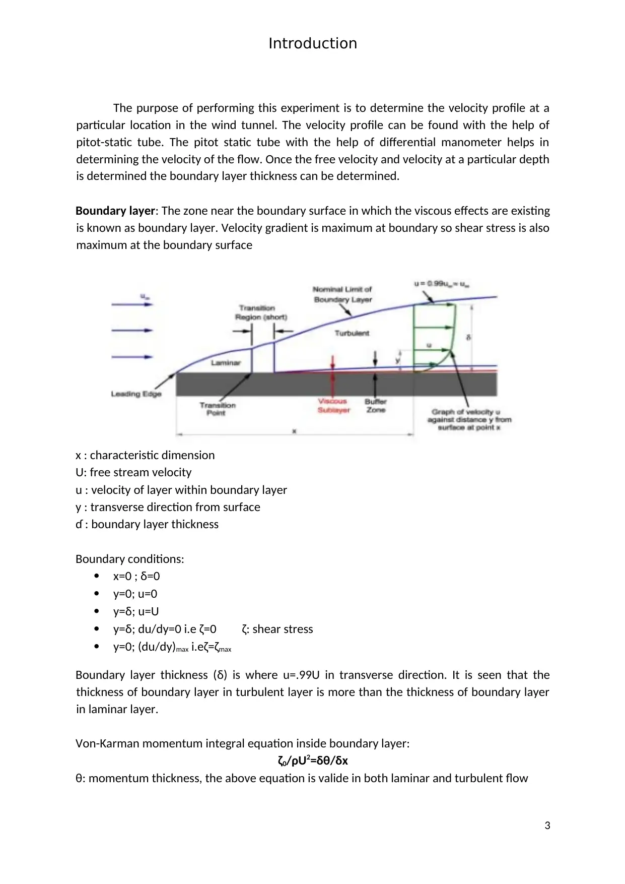
Boundary layer: The zone near the boundary surface in which the viscous effects are existing
is known as boundary layer. Velocity gradient is maximum at boundary so shear stress is also
maximum at the boundary surface
x : characteristic dimension
U: free stream velocity
u : velocity of layer within boundary layer
y : transverse direction from surface
ɗ : boundary layer thickness
Boundary conditions:
x=0 ; δ=0
y=0; u=0
y=δ; u=U
y=δ; du/dy=0 i.e ζ=0 ζ: shear stress
y=0; (du/dy)max i.eζ=ζmax
Boundary layer thickness (δ) is where u=.99U in transverse direction. It is seen that the
thickness of boundary layer in turbulent layer is more than the thickness of boundary layer
in laminar layer.
Von-Karman momentum integral equation inside boundary layer:
ζ0/ρU2=δθ/δx
θ: momentum thickness, the above equation is valide in both laminar and turbulent flow
3
Local cf(x) and average cD skin/drag coeffiecents:
Cf(x): it is defined at any particular section as the ratio of wall shear stress at that section to
the dynamic pressure whereas
CD : defined as ratio of average shear stress to dynamic pressure.
Usually CD = 2Cf(x)
Results given by Von-karman are analytical and those given by Blausis is experimental. Some
of the values of boundary layer, local skin coefficient and average skin coefficients are as
follows:
Blausis solution for laminar flow:
δ = 5x/√ Rex; cf(x) = 0.664/ √ Rex and CD = 1.328/ √ Rex
Von-karman results for turbulent flow:
δ = 0.375x/(Rex)1/5; cf(x) = 0.059/(Rex)1/5 and CD= 5/4 cf(x) where Rex: Reynold’s number
Measurement of pressure in fluid is by manometer which is simple and differential in nature.
The simple manometer consists of piezometer and U-tube manometer.
Static, Stagnation, dynamic and total pressure:
The principle of Bernaulli’s equation deals with conservation of energy of associated
with the flowing fluid . Pressure arises from the conversion of kinetic energy into pressure
energy when the flowing fluid is brought to rest. Static pressure is the measure of the
amount by which the fluid pressure exceeds the local pressure. Stagnation pressure is the
measure of the amount by which the fluid pressure exceeds the local atmospheric pressure
taking into consideration the effect of the fluid velocity. Dynamic pressure is the measure of
the amount by which the stagnation pressure exceeds the static pressure at any point in the
fluid
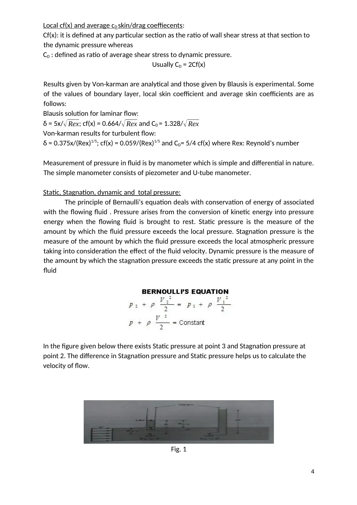
In the figure given below there exists Static pressure at point 3 and Stagnation pressure at
point 2. The difference in Stagnation pressure and Static pressure helps us to calculate the
velocity of flow.
Fig. 1
4
Secure Best Marks with AI Grader
Need help grading? Try our AI Grader for instant feedback on your assignments.
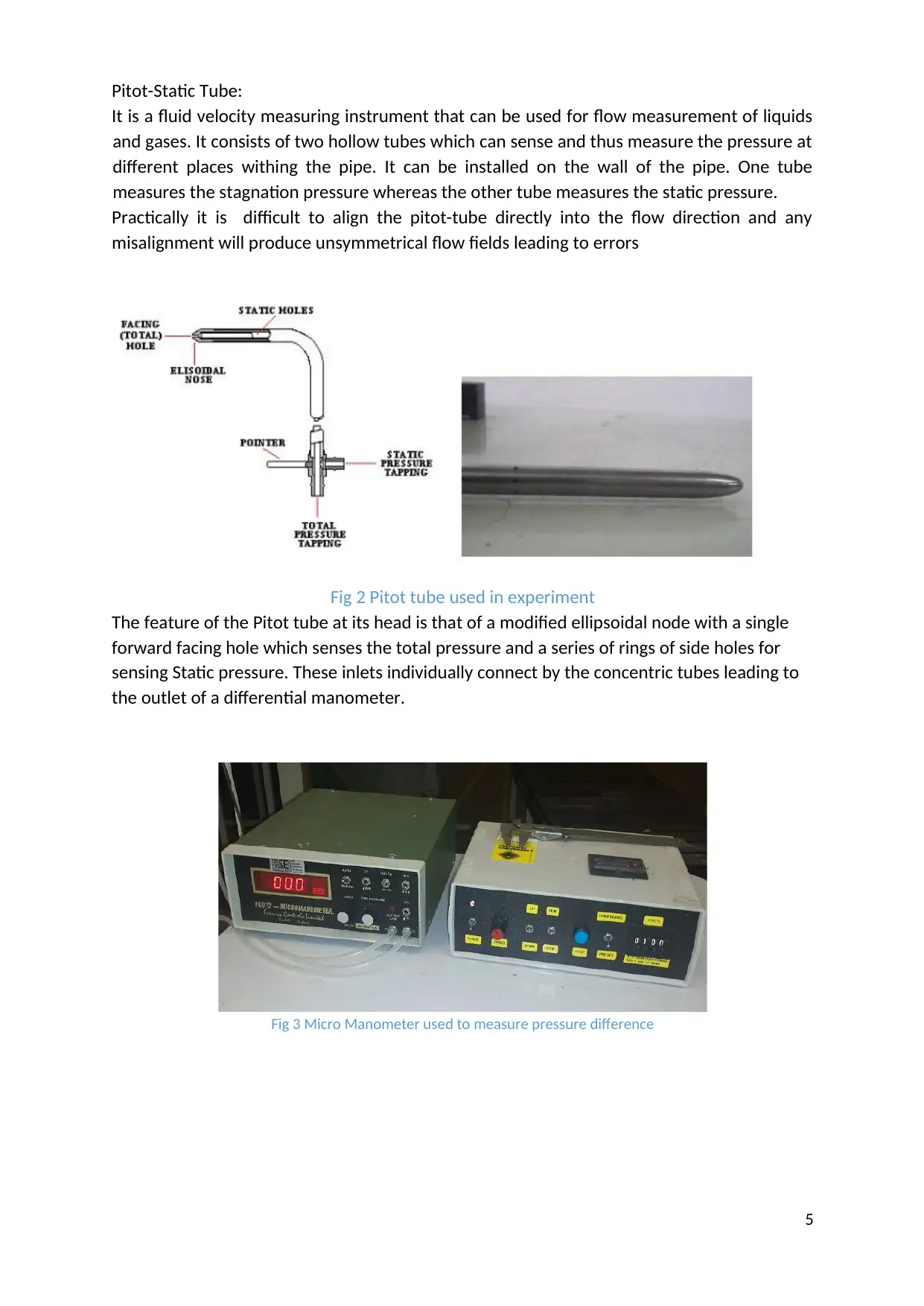
Pitot-Static Tube:
It is a fluid velocity measuring instrument that can be used for flow measurement of liquids
and gases. It consists of two hollow tubes which can sense and thus measure the pressure at
different places withing the pipe. It can be installed on the wall of the pipe. One tube
measures the stagnation pressure whereas the other tube measures the static pressure.
Practically it is difficult to align the pitot-tube directly into the flow direction and any
misalignment will produce unsymmetrical flow fields leading to errors
Fig 2 Pitot tube used in experiment
The feature of the Pitot tube at its head is that of a modified ellipsoidal node with a single
forward facing hole which senses the total pressure and a series of rings of side holes for
sensing Static pressure. These inlets individually connect by the concentric tubes leading to
the outlet of a differential manometer.
Fig 3 Micro Manometer used to measure pressure difference
5
Theory of Experiment
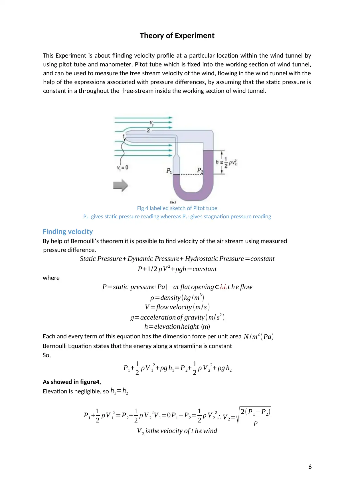
This Experiment is about fiinding velocity profile at a particular location within the wind tunnel by
using pitot tube and manometer. Pitot tube which is fixed into the working section of wind tunnel,
and can be used to measure the free stream velocity of the wind, flowing in the wind tunnel with the
help of the expressions associated with pressure differences, by assuming that the static pressure is
constant in a throughout the free-stream inside the working section of wind tunnel.
Fig 4 labelled sketch of Pitot tube
P2: gives static pressure reading whereas P1: gives stagnation pressure reading
Finding velocity
By help of Bernoulli’s theorem it is possible to find velocity of the air stream using measured
pressure difference.
Static Pressure+ Dynamic Pressure+ Hydrostatic Pressure =constant
P+1/2 ρV 2 + ρgh=constant
where
P=static pressure ( Pa ) −at flat opening∈¿¿ t h e flow
ρ=density (kg /m3)
V =flow velocity (m/s )
g=acceleration of gravity ( m/ s2 )
h=elevationheight (m)
Each and every term of this equation has the dimension force per unit area N /m2 ( Pa)
Bernoulli Equation states that the energy along a streamline is constant
So,
P1 +1
2 ρV 1
2 +ρg h1=P2+ 1
2 ρ V 2
2+ ρg h2
As showed in figure4,
Elevation is negligible, so h1=h2
P1 +1
2 ρV 1
2=P2+ 1
2 ρ V 2
2V 1=0P1−P2= 1
2 ρ V 2
2
∴ V 2= √ 2( P1−P2)
ρ
V 2 isthe velocity of t h e wind
6
For the liquid column manometer Psg- Pst = ∆P
∆H = ∆ P /ρ ' g (∆H is the difference in water column in meters) ……………… (3)
Substituting the value of ∆P in terms of ∆H we will get
V = √ 2(∆ H ρ' g)
ρ ……………………………………………………………………………….… (4)
ρ' : is the density of the water used in manometer.
ρ :density of air flowing through the tube.
U: is the velocity of the air stream.
U1: √ 2∗(0.0128∗998.23∗9.81)
1.2754
: 14.019954m/s
U :
√ 2∗( 0.0206∗998.23∗9.81)
1.2754
:17.78574m/s
Similarly we can calculate the other values of velocity based on ∆H values
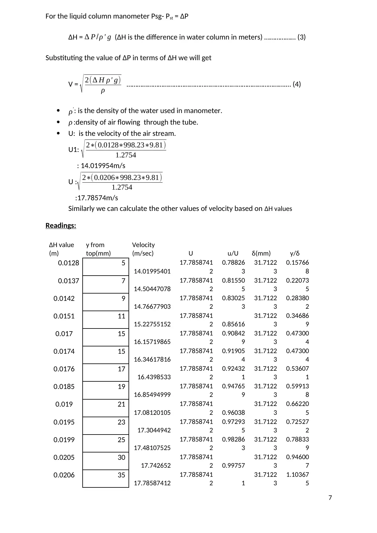
Readings:
∆H value
(m)
y from
top(mm)
Velocity
(m/sec) U u/U δ(mm) y/δ
0.0128 5
14.01995401
17.7858741
2
0.78826
3
31.7122
3
0.15766
8
0.0137 7
14.50447078
17.7858741
2
0.81550
5
31.7122
3
0.22073
5
0.0142 9
14.76677903
17.7858741
2
0.83025
3
31.7122
3
0.28380
2
0.0151 11
15.22755152
17.7858741
2 0.85616
31.7122
3
0.34686
9
0.017 15
16.15719865
17.7858741
2
0.90842
9
31.7122
3
0.47300
4
0.0174 15
16.34617816
17.7858741
2
0.91905
4
31.7122
3
0.47300
4
0.0176 17
16.4398533
17.7858741
2
0.92432
1
31.7122
3
0.53607
1
0.0185 19
16.85494999
17.7858741
2
0.94765
9
31.7122
3
0.59913
8
0.019 21
17.08120105
17.7858741
2 0.96038
31.7122
3
0.66220
5
0.0195 23
17.3044942
17.7858741
2
0.97293
5
31.7122
3
0.72527
2
0.0199 25
17.48107525
17.7858741
2
0.98286
3
31.7122
3
0.78833
9
0.0205 30
17.742652
17.7858741
2 0.99757
31.7122
3
0.94600
7
0.0206 35
17.78587412
17.7858741
2 1
31.7122
3
1.10367
5
7
Paraphrase This Document
Need a fresh take? Get an instant paraphrase of this document with our AI Paraphraser
0.0206 40
17.78587412
17.7858741
2 1
31.7122
3
1.26134
3
0.0206 45
17.78587412
17.7858741
2 1
31.7122
3
1.41901
1
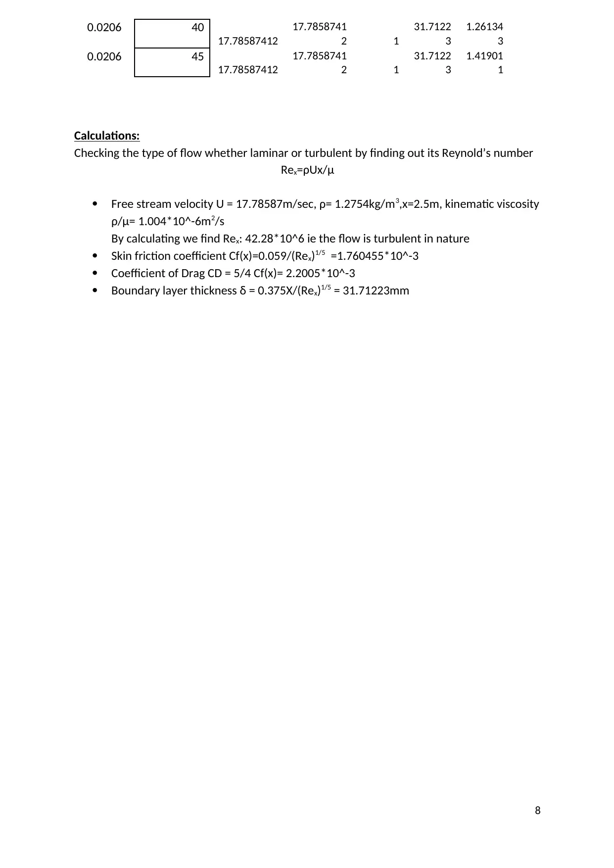
Calculations:
Checking the type of flow whether laminar or turbulent by finding out its Reynold’s number
Rex=ρUx/μ
Free stream velocity U = 17.78587m/sec, ρ= 1.2754kg/m3,x=2.5m, kinematic viscosity
ρ/μ= 1.004*10^-6m2/s
By calculating we find Rex: 42.28*10^6 ie the flow is turbulent in nature
Skin friction coefficient Cf(x)=0.059/(Rex)1/5 =1.760455*10^-3
Coefficient of Drag CD = 5/4 Cf(x)= 2.2005*10^-3
Boundary layer thickness δ = 0.375X/(Rex)1/5 = 31.71223mm
8
17.78587412
17.7858741
2 1
31.7122
3
1.26134
3
0.0206 45
17.78587412
17.7858741
2 1
31.7122
3
1.41901
1
Calculations:
Checking the type of flow whether laminar or turbulent by finding out its Reynold’s number
Rex=ρUx/μ
Free stream velocity U = 17.78587m/sec, ρ= 1.2754kg/m3,x=2.5m, kinematic viscosity
ρ/μ= 1.004*10^-6m2/s
By calculating we find Rex: 42.28*10^6 ie the flow is turbulent in nature
Skin friction coefficient Cf(x)=0.059/(Rex)1/5 =1.760455*10^-3
Coefficient of Drag CD = 5/4 Cf(x)= 2.2005*10^-3
Boundary layer thickness δ = 0.375X/(Rex)1/5 = 31.71223mm
8
Discussion of Results:
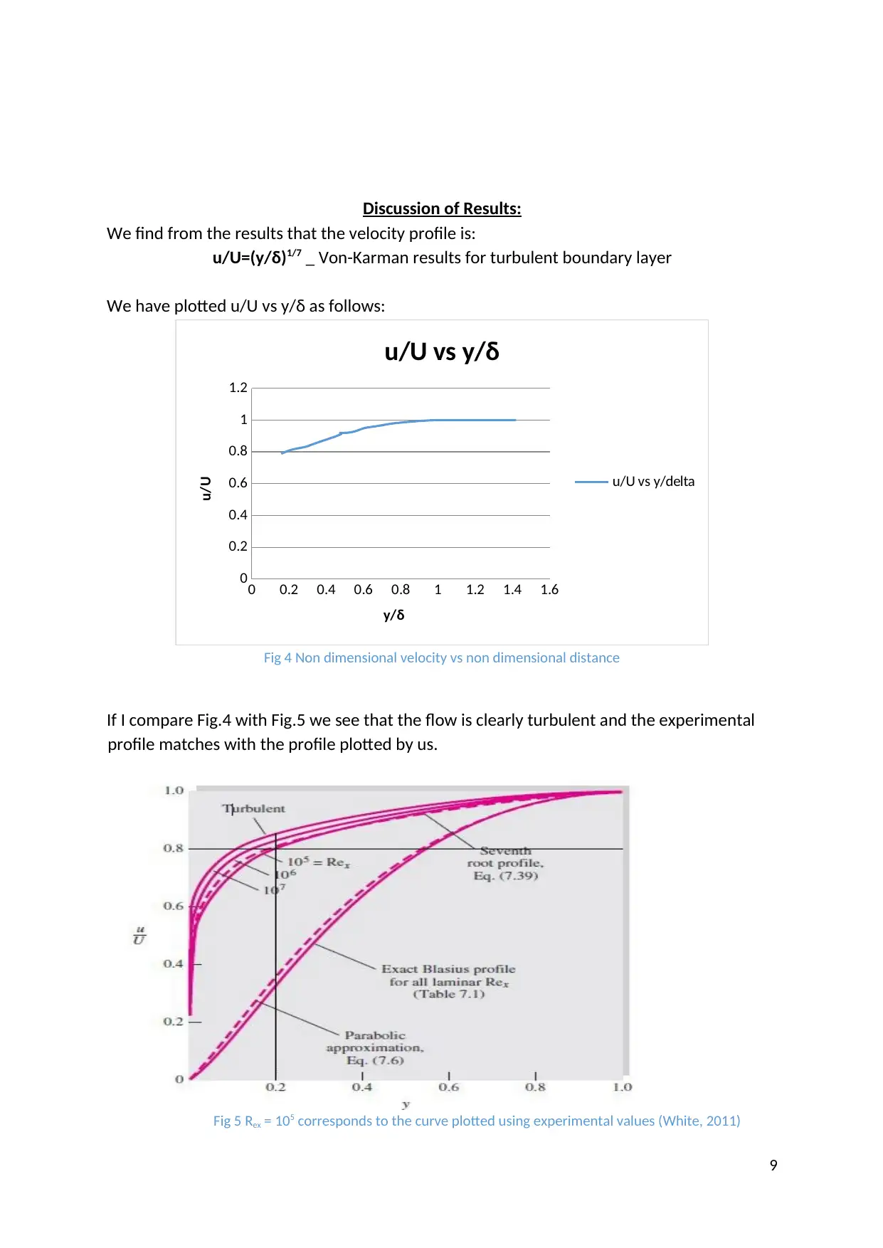
We find from the results that the velocity profile is:
u/U=(y/δ)1/7 _ Von-Karman results for turbulent boundary layer
We have plotted u/U vs y/δ as follows:
0 0.2 0.4 0.6 0.8 1 1.2 1.4 1.6
0
0.2
0.4
0.6
0.8
1
1.2
u/U vs y/δ
u/U vs y/delta
y/δ
u/U
Fig 4 Non dimensional velocity vs non dimensional distance
If I compare Fig.4 with Fig.5 we see that the flow is clearly turbulent and the experimental
profile matches with the profile plotted by us.
Fig 5 Rex = 105 corresponds to the curve plotted using experimental values (White, 2011)
9
5.0 References:
- Bruce R.Munson, Donald F.Young and Theodore H.Okiishi (2014) Fundamentals of Fluid
Mechanics. 5th ed. Wiley publications.
- White, F.M (2011) Fluid mechanics. 7th ed. New York, NY, United States: McGraw Hill
Higher Education.
- eFunda (2016), Pitot static tubes theory.
Availablefrom:www.efunda.com/designstandards/sensors/pitot_tubes_theory
10
Secure Best Marks with AI Grader
Need help grading? Try our AI Grader for instant feedback on your assignments.
11
1 out of 11
Your All-in-One AI-Powered Toolkit for Academic Success.
+13062052269
info@desklib.com
Available 24*7 on WhatsApp / Email
Unlock your academic potential
© 2024 | Zucol Services PVT LTD | All rights reserved.