Food Drying Solution 2022
VerifiedAdded on 2022/10/03
|56
|14996
|17
AI Summary
Contribute Materials
Your contribution can guide someone’s learning journey. Share your
documents today.

Secure Best Marks with AI Grader
Need help grading? Try our AI Grader for instant feedback on your assignments.
Abstract
Food drying is an economical solution to preserve crops, fruits and meat products
without refrigeration. Dried food products can be easily stored at room temperature
over a prolonged duration of time. Also, dried foods are highly marketable because
the ease of transporting, storing and distributing. Food drying can be accomplished
by a number of different methods. The simplest and oldest method is open-sun
drying, where the products are exposed to the sunlight by spreading them over a
surface. To enhance the quality and prevent spoilage, modern solar drying systems
are used. A solar drying system keeps the crops inside a drying chamber. The
required heat may be provided by direct application of the sunlight or by means of an
indirect drying system, where heat is collected by an absorber and then transferred
to the drying chamber. The advantage of indirect drying is the preservation of
vitamins and color. The choice of the type, size and mechanism of a solar drying
system is a challenging design task. In this project, a solar drying system with heat
exchanger is designed for a food factory in Australia. The design scheme takes into
account the environmental conditions (temperature, solar irradiation, etc.) at the
location of interest. Furthermore, the cost of the system is considered as a key
parameter in the design process. This way, a comprehensive design scheme will be
developed, which considers both physical and financial constraints.) Also, at the
location of interest. A result That find by using a heat exchanger is a highest and
lowest temperature out. Also Find an area of heat exchanger by measure a
temperature out.
Contents
Abstract..............................................................................................................................
Chapter 1. Introduction....................................................................................................
Chapter 2. Literature review............................................................................................
2.1 Introduction...........................................................................................................
2.2 Open air drying.....................................................................................................
2.3 Solar drying systems............................................................................................
2.3.1 Direct solar drying........................................................................................
2.3.2 Indirect solar drying.....................................................................................
2.4 Crop drying model..............................................................................................
2.4.1 Concept of moisture content........................................................................
2.4.2 Heat transfer model.....................................................................................
2.4.3 Mass transfer model....................................................................................
2.5 Hybrid solar drying system.................................................................................
Chapter 3. Research questions.....................................................................................
Chapter 4. Research Methodology................................................................................
4.1.1 Mathematical modeling................................................................................
4.1.2 System specifications..................................................................................
4.2 Efficiency of flat plate solar collector..................................................................
4.2.1 Mathematical analysis.................................................................................
4.2.2 Evaluation of the efficiency curve for the selected collector........................
Chapter 5. Data Collection............................................................................................
Chapter 6. Preliminary Simulation results.....................................................................
Chapter 7. Conclusions and future work.......................................................................
Chapter 8. Timeline/ Project Management....................................................................
References.......................................................................................................................
List of Figures
Figure 1. Open air solar drying (Tomar et al., 2017)........................................................
Figure 2. Tree diagram of different types of solar drying systems (Mustayen et al.,
2014) 9
Figure 3. Direct solar drying (Tomar et al., 2017)..........................................................
Figure 4. Indirect solar drying (Tomar et al., 2017)........................................................
Figure 5. Schematic diagram of a hybrid solar drying system.......................................
Figure 6. Operation of the hybrid thermal system..........................................................
Figure 7. Photo of the solar drying system.....................................................................
Figure 8. Schematic of the section of the flat dual function collector.............................
Figure 9. Thermal model of the flat dual function collector............................................
Figure 10. Linear curve of collector’s efficiency............................................................
Figure 11. Variations of irradiance in W/sq m in NSW (Wagga Wagga). a) sunny
day, b) cloudy day (Meteorology, 2019a)........................................................................
Figure 12. Variations of temperature recorded at Sydney Observatory Hill. a)
January 2018, b) June 2018 (Meteorology, 2019b)........................................................
Figure 13. Monthly average value of a) solar irradiance, b) ambient temperature, c)
humidity ratio...................................................................................................................
Figure 14. Output energy of the solar collector.............................................................
Secure Best Marks with AI Grader
Need help grading? Try our AI Grader for instant feedback on your assignments.
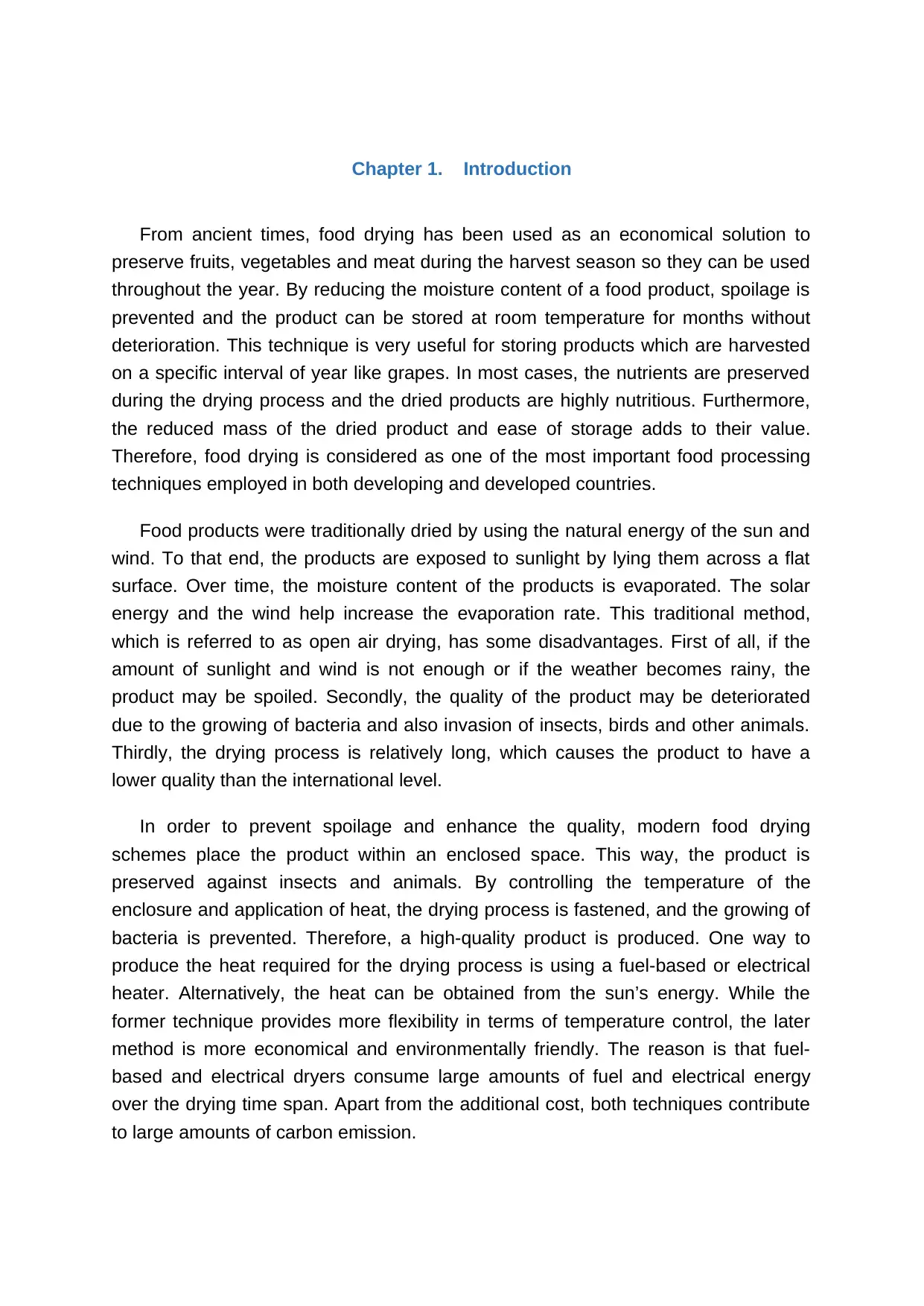
Chapter 1. Introduction
From ancient times, food drying has been used as an economical solution to
preserve fruits, vegetables and meat during the harvest season so they can be used
throughout the year. By reducing the moisture content of a food product, spoilage is
prevented and the product can be stored at room temperature for months without
deterioration. This technique is very useful for storing products which are harvested
on a specific interval of year like grapes. In most cases, the nutrients are preserved
during the drying process and the dried products are highly nutritious. Furthermore,
the reduced mass of the dried product and ease of storage adds to their value.
Therefore, food drying is considered as one of the most important food processing
techniques employed in both developing and developed countries.
Food products were traditionally dried by using the natural energy of the sun and
wind. To that end, the products are exposed to sunlight by lying them across a flat
surface. Over time, the moisture content of the products is evaporated. The solar
energy and the wind help increase the evaporation rate. This traditional method,
which is referred to as open air drying, has some disadvantages. First of all, if the
amount of sunlight and wind is not enough or if the weather becomes rainy, the
product may be spoiled. Secondly, the quality of the product may be deteriorated
due to the growing of bacteria and also invasion of insects, birds and other animals.
Thirdly, the drying process is relatively long, which causes the product to have a
lower quality than the international level.
In order to prevent spoilage and enhance the quality, modern food drying
schemes place the product within an enclosed space. This way, the product is
preserved against insects and animals. By controlling the temperature of the
enclosure and application of heat, the drying process is fastened, and the growing of
bacteria is prevented. Therefore, a high-quality product is produced. One way to
produce the heat required for the drying process is using a fuel-based or electrical
heater. Alternatively, the heat can be obtained from the sun’s energy. While the
former technique provides more flexibility in terms of temperature control, the later
method is more economical and environmentally friendly. The reason is that fuel-
based and electrical dryers consume large amounts of fuel and electrical energy
over the drying time span. Apart from the additional cost, both techniques contribute
to large amounts of carbon emission.
The solar dryers are not only clean but also cheap to operate. Although some
solar dryers rely on electrical energy for air circulation, their energy consumption is
much less than the alternative solutions. A variety of solar drying systems have been
proposed in the literature and implemented in practice. Basically, these methods can
be categorized into direct and indirect drying schemes. In the direct drying method,
the enclosure is covered by a transparent cover. The sunlight passes from the cover
and reaches the product, which is laid on a surface beneath the cover. Therefore,
the products are dried through the direct action of the sunlight without being
exposed. Alternatively, the sunlight can be collected by a solar energy collector and
transferred to the products. The main advantage of the indirect method is the ability
to control the temperature and also the possibility of storing energy during midday
and using it later on at nights (Baniasadi et al., 2017). It is worth mentioning that due
to the complexity and additional cost of the indirect method, its application is mainly
limited to food factories. The direct method, on the other hand, may be used in on-
site drying stations owned by farmers or inside food factories (Chauhan et al., 2015).
This project is focused on design of solar drying systems for food factories. The
research aims at designing a solar food drying system for a food factory in Australia.
A mathematical model of the system is developed and implemented using computer
aided simulations. The computer-based simulations are used to analyze the
technical and economical characteristics of the system and fit the design with the
requirements.
The customary drying framework to safeguard organic products, vegetables, grains,
fish, meat, wood, and other rural items is sun-drying which is a free and
inexhaustible wellspring of vitality. Be that as it may, for enormous scale generation,
there are differently referred to constraints of sun drying as harm to the crops by
creatures, winged animals and rodents, debasement in quality due to direct
introduction to sun-powered radiation, dew or downpour, sullying by soil, residue or
trash. Additionally, this framework is work and time escalated, as harvests must be
secured around evening time and during awful climate, and must be shielded from
assault by residential creatures. There is likewise an opportunity of creepy-crawly
pervasion and development of microorganisms due to non-uniform drying.
The progression of sun drying is sun oriented drying frameworks in which items are
dried in a shut framework in which inside temperature is higher. The real preferred
position incorporates assurance against flies, bothers, downpour or residue. A few
significant endeavors have been made in later a long time to bridle sun powered
vitality for drying, for the most part, to protect farming items and get the benefits from
the vitality given by the sun. Sun drying of yields is the most boundless technique for
nourishment conservation in most pieces of India and the world in light of sun-based
irradiance being very high for the greater part of the year. As this strategy needs no
vitality during day time, it is more beneficial to the little scale ranchers who can't
a ord the power or other fuel for drying. On the off chance that it is important to dryff
items in the night or awful climate, an extra bio-fueled radiator can be utilized for
warmth supply. Because of their high dampness content at gather, 60 to 70% web,
common ready espresso fruits don't stream effectively in taking care of gear (for
example gravity gushes, containers, can lifts, wood screws) and traditional
mechanical dryers.
The rest of the report is organized as follows. To gain an in depth understanding of
the research field, the structure and mathematical model of food drying systems are
reviewed in Chapter 2. Then, the specific research objectives are indicated in
Chapter 3 in the form of a list of questions. Next, the research methodology including
mathematical model of the proposed solar drying system is detailed in Chapter 4.
The data collection including assessment of weather conditions is addressed in
Chapter 5. Chapter 6 presents some preliminary simulation results obtained from F-
charts program. Conclusion and project management are then presented in
Chapters 7 and 8.
Once of the major objectives to have a temperature for a given amount of heat
transferred by design of heat exchanger. A heat exchanger have a crossflow tubular
have been studied by many investigators, with most of the experiments performed
on exchangers (E.K. Ruth 1983). From old occasions, sustenance drying has been
utilized as a practical answer for protect natural products, vegetables and meat
during the reap season so they can be utilized consistently. By lessening the
dampness substance of a sustenance item, decay is counteracted, and the item can
be put away at room temperature for quite a long time without weakening. This
procedure is exceptionally helpful for putting away items which are gathered on a
particular interim of year like grapes. Much of the time, the supplements are
protected during the drying procedure and the dried items are exceptionally
nutritious. Besides, the decreased mass of the dried item and simplicity of capacity
adds to their worth. Accordingly, sustenance drying is considered as one of the most
significant nourishment handling methods utilized in both creating and created
nations. growing of bacteria and also invasion of Nourishment items were
customarily dried by utilizing the regular vitality of the sun and wind. With that in
mind, the items are presented to daylight by lying them over a level surface. After
some time, the dampness substance of the items is dissipated. The sun based
vitality and the breeze help increment the dissipation rate. Additionally, with utilizing
heat exchanger there will be more item and best quality. This customary strategy,
which is alluded to as outdoors drying, has a few detriments. Above all else, if the
measure of daylight and wind isn't sufficient or if the climate ends up blustery, the
item might be ruined. Besides, the nature of the item might be crumbled because of
Paraphrase This Document
Need a fresh take? Get an instant paraphrase of this document with our AI Paraphraser
the developing of microbes and furthermore attack of creepy crawlies, flying
creatures and different creatures. Thirdly, the drying procedure is moderately long,
which makes the item have a lower quality than the universal level.
Ordinary drum-type rotational dryers are an option, yet they are by and large
reprimanded for having wind stream issues and low vitality proficiency. Because of
this, the run of the mill espresso drying process in Brazil comprises of two distinctive
drying stages.
In the principal organize, newly gathered entire espresso fruits are spread on cleared
patios where they are permitted to dry under the sun until they arrive at 35 to
30%dampness content, though in the second stage the espresso is dried in high-
temperature mechanical dryers down to about 13% w.b .Adjustments in the drawing
and the treatment of the drum-type turning dryer, achieved by specialists from
Universidad Federal de Visas (UFV), Brazil, demonstrate that the previously
mentioned issues might be effectively unraveled, and can change the rotational dryer
into appropriate hardware to work with normal, cherry,espresso.On the off chance
that the atmosphere is to such an extent that reliable daylight is accessible during
the collect
season, the drying procedure might be directed altogether on the outside. In this
case, fruits are spread out on the drying patio in the wake of collecting and dried
to about 13% dampness content in a solitary activity. Another option is the complete
drying of entire espresso fruits in a fixed-bed dryer or the most up to date framework
for espresso drying, the 'half breed patio'. The important disadvantage of using
ordinary mechanical dryers have been the reality of their being structured principally
to dry items other than espresso, and their relative significant expense. In spite of the
ongoing endeavors to change this circumstance a large portion of the industrially
accessible dryers are as yet wasteful and have so far been fundamentally utilized in
enormous scale activities. Sincé 1998, the CBP&D-Café (Consórcio Brasileiro de
Pesquisa e
Desenvolvimento do Café), through the Universidade Federal de Viçosa, has been
creating for the espresso cultivator drying, and capacity innovations adjusted for
little espresso generation frameworks, as sketched out underneath. Some creative
grain drying techniques, for the most part, applied to oats and oilseeds, have been
brought into espresso drying offices over the most recent couple of years in an
exertion to expand the drying limit and the vitality productivity of traditional espresso
drying establishments, and simultaneously to keep up high espresso quality.
Heat exchangers are devices that transfer energy between fluids at different
temperatures by heat transfer (Cuneyt Ezgi, 2017). In order to prevent spoilage and
enhance the quality, modern food drying schemes place the application is mainly
limited to food factories. The direct method, on the other hand, may be used in on-
site drying stations onwed by farmers or inside food factories (Chauhan, Kumar et al.
2015). Along these lines, the item is safeguarded against creepy crawlies and
creatures. By controlling the temperature of the walled in area and use of warmth,
the drying procedure is secured, and the developing of microbes is anticipated. In
this manner, a top notch item is created. One approach to deliver the warmth
required for the drying procedure is utilizing a fuel-based or electrical warmer. Then
again, the warmth can be gotten from the sun's vitality. While the previous strategy
gives greater adaptability as far as temperature control, the later technique is
increasingly affordable and naturally well disposed. The reason is that fuel-based
and electrical dryers expend a lot of fuel and electrical vitality over the drying time
length. Aside from the extra cost, the two procedures add to a lot of carbon
emanation.
Heat exchanger are devices that transfer energy between fluids at different
temperatures by heat transfer. The heat exchanger is a best modern way that factory
used it and human. It’s clean, cheap and safety. This heat exchanger is not need to
used electricity. It can connect with solar system to work and produce temperature
out. The type of heat exchanger is used is single-pass cross-flow with both fluids
unmixed. This model can be used day and night. It’s saved a lot of time and easy to
use. In contrast, the regenerators are devices in which there is intermittent heat
exchanger between the hot and cold fluids through thermal energy storage and
release through the heat exchanger surface. The heat exchanger it can small and
big and the different is area that can be have high temperature. So Small will be
have low temperature then the temperature is depending on area of heat exchanger.
The sun oriented drying it's the procedure which gives the free the vitality of energy
used in the drying space for dissipated the water into apricot. In this investigation, we
plan both of sun-based authority and the drying chamber which incorporate with it,
which give one arrangement of drying, we are attempting to test the apricot by it and
the outcome talk about this plan acknowledged, it is the perception study. An
improved innovation in using sunlight-based vitality for drying agrarian is the
utilization of sunlight-based dryers where the air is warmed in a sunlight-based
authority and afterward went through items.
There are two fundamental kinds of sun-powered dryer fitting for use with agrarian:
regular convection dryers where the air the stream is incited by warm slopes; and
constrained convection
dryers wherein air is constrained through a sunlight-based authority. In this study the
drying sunlight based with constrained convection, The constrained
convection sunlight-based dryer can be considered as an ordinary mechanical drying
framework in which air is constrained through a dried item holder however the air is
warmed by a level plate sunlight-based authority as opposed to by increasingly
traditional methods.
Most creating nations can't settle their nourishment issues for then tire populace as a
result of the quickly expanding the number of individuals in their separate domains.
Some exploration exertion to plan and build up a constrained convection sun-
powered dryer utilizing emptied cylinder air gatherer
Their exhibition was contrasted and characteristic sun drying. The consequences of
the present investigation demonstrate that the proposed sun based the dryer has
been more noteworthy effectiveness and the dampness substance of the harsh
gourd is decreased from 91% to 6.25% in 6 hours as contrasted with 10 hours in
common sun-drying . Another work thinks about an exploratory investigation was
directed to research the exhibition of an exclusively sun oriented drying framework
and a framework outfitted with an assistant warmer as an enhancement to the
sunlight-based warmth, . The exhibitions of both are contrasted with that of regular
drying. Beans and peas are got dried out in a framework that comprises of a two-
level plate authority, a blower, and a drying chamber. Tests with four diverse wind
stream rates, specifically, 0.0383, 0.05104, 0.0638, and 0.07655 m3/s were directed.
The effectiveness of the blended the drying framework was found to increment by
25% to 40% contrasted with the exclusively sun oriented drying. The best fit for the
trial information of peas and beans was acquired by six exponential conditions for
the different frameworks with a relationship coefficient in the range of 0.933 and
0.997.
Hot water enters
Secure Best Marks with AI Grader
Need help grading? Try our AI Grader for instant feedback on your assignments.
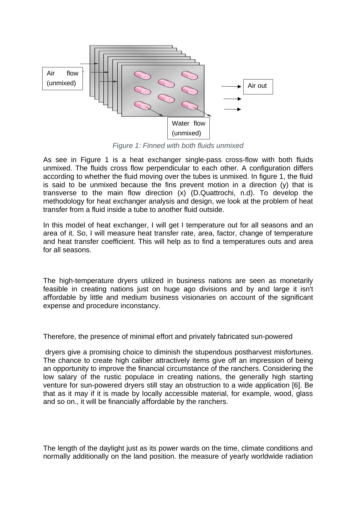
Figure 1: Finned with both fluids unmixed
As see in Figure 1 is a heat exchanger single-pass cross-flow with both fluids
unmixed. The fluids cross flow perpendicular to each other. A configuration differs
according to whether the fluid moving over the tubes is unmixed. In figure 1, the fluid
is said to be unmixed because the fins prevent motion in a direction (y) that is
transverse to the main flow direction (x) (D.Quattrochi, n.d). To develop the
methodology for heat exchanger analysis and design, we look at the problem of heat
transfer from a fluid inside a tube to another fluid outside.
In this model of heat exchanger, I will get I temperature out for all seasons and an
area of it. So, I will measure heat transfer rate, area, factor, change of temperature
and heat transfer coefficient. This will help as to find a temperatures outs and area
for all seasons.
The high-temperature dryers utilized in business nations are seen as monetarily
feasible in creating nations just on huge ago divisions and by and large it isn't
a ordable by little and medium business visionaries on account of the significantff
expense and procedure inconstancy.
Therefore, the presence of minimal effort and privately fabricated sun-powered
dryers give a promising choice to diminish the stupendous postharvest misfortunes.
The chance to create high caliber attractively items give off an impression of being
an opportunity to improve the financial circumstance of the ranchers. Considering the
low salary of the rustic populace in creating nations, the generally high starting
venture for sun-powered dryers still stay an obstruction to a wide application [6]. Be
that as it may if it is made by locally accessible material, for example, wood, glass
and so on., it will be financially a ordable by the ranchers.ff
The length of the daylight just as its power wards on the time, climate conditions and
normally additionally on the land position. the measure of yearly worldwide radiation
Air flow
(unmixed)
Water flow
(unmixed)
Air out
on
the flat surface may in this way reach in the Sun Belt locales more than 2,200
kWh/m2. the worldwide radiation makes out of direct and di use radiation.ff
The direct sunlight-based radiation is the part which tumbles from the course of the
sun . The di use radiation part is made at the point when the direct sunlight-basedff
beams are dispersed from the di erent particles what's more, particles in the air intoff
all headings, for example, the radiation winds up scattered. The 14 measure of
di use radiation is needy on the climatic and geographic conditions. the worldwideff
radiation and the extent of di use radiation is extraordinarily a ected by mists, theff ff
state of the environment (for example cloudiness and residue layers) and the way
length of the pillars through the environment.
The sun is the base vitality maker of our close planetary system. Since of nonstop
atomic combination occurring in its center, a huge the measure of vitality is created;
a little part of the vitality delivered in the sun hits the earth and makes life
conceivable on our planet. Sun based radiation causes every single regular cycle
and exercises, for example, downpour, wind, sea flows, photosynthesis, and a few
other marvels which are essential forever. the whole world vitality need has been
based on the absolute starting point on sunlight-based vitality [7-9]. Every single
petroleum product (coal, gas, oil) are changed over the type of sunlight-based
vitality. The sunlight-based surface temperature of the sun is 6000°C which relates to
70,000 to 80,000 kW/m2 radiation force. Earth gets just a little bit of this vitality. In
dislike of this, the approaching sun-oriented radiation vitality in a year is around 2×
1017 kWh; this is above multiple times the yearly vitality request of the entire world .
The sun-oriented radiation power outside the climate is about 1,360 W/m2 (sun
oriented consistent).
Chapter 2. Literature review
2.1 Introduction
As the most abundant energy on earth, solar energy has the potential of meeting the
entire energy requirements. The challenge, however, is to harvest the sun’s energy. In
general, the solar energy can be harvested using two different methods, namely by using
photovoltaic cells or thermal solar collectors. The photovoltaic cells convert the sunlight’s
energy into electrical energy which can either be used locally or injected to the electrical
grid. The solar collectors, on the other hand, use sunlight to generate thermal energy,
which can be used within residential, commercial or industrial buildings (Selvaraj et al.,
2018).
Solar thermal systems can provide a great amount of energy saving for industrial
applications. Solar On the one hand, the majority of the energy consumption in industrial
sector is in the form of thermal energy. On the other hand, the industrial processes
consume the energy at a steady pace. For instance, in a dairy factory, the pasteurization
and sterilization processes require a steady flow of thermal energy. Another example is the
food drying factories, in which thermal energy is used to facilitate vaporizing the moisture
content of the food products. Although the required heat can be generated using diesel or
and electrical heater, the fuel and electrical energy consumption greatly increases the
costs. Moreover, the carbon emission resulting from burning diesel fuel on-site or other
fossil fuels in electrical power plants adversely affect the environment. To solve these
issues, solar energy can be used as a clean and free source of energy.
In this chapter, three different solar drying approaches, namely open-air drying, direct
drying and indirect drying are reviewed. Furthermore, the drying mechanism is studied and
the mathematical model of the drying system is addressed.
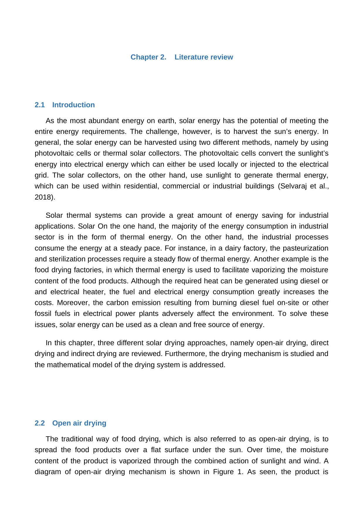
2.2 Open air drying
The traditional way of food drying, which is also referred to as open-air drying, is to
spread the food products over a flat surface under the sun. Over time, the moisture
content of the product is vaporized through the combined action of sunlight and wind. A
diagram of open-air drying mechanism is shown in Figure 1. As seen, the product is
2.1 Introduction
As the most abundant energy on earth, solar energy has the potential of meeting the
entire energy requirements. The challenge, however, is to harvest the sun’s energy. In
general, the solar energy can be harvested using two different methods, namely by using
photovoltaic cells or thermal solar collectors. The photovoltaic cells convert the sunlight’s
energy into electrical energy which can either be used locally or injected to the electrical
grid. The solar collectors, on the other hand, use sunlight to generate thermal energy,
which can be used within residential, commercial or industrial buildings (Selvaraj et al.,
2018).
Solar thermal systems can provide a great amount of energy saving for industrial
applications. Solar On the one hand, the majority of the energy consumption in industrial
sector is in the form of thermal energy. On the other hand, the industrial processes
consume the energy at a steady pace. For instance, in a dairy factory, the pasteurization
and sterilization processes require a steady flow of thermal energy. Another example is the
food drying factories, in which thermal energy is used to facilitate vaporizing the moisture
content of the food products. Although the required heat can be generated using diesel or
and electrical heater, the fuel and electrical energy consumption greatly increases the
costs. Moreover, the carbon emission resulting from burning diesel fuel on-site or other
fossil fuels in electrical power plants adversely affect the environment. To solve these
issues, solar energy can be used as a clean and free source of energy.
In this chapter, three different solar drying approaches, namely open-air drying, direct
drying and indirect drying are reviewed. Furthermore, the drying mechanism is studied and
the mathematical model of the drying system is addressed.
2.2 Open air drying
The traditional way of food drying, which is also referred to as open-air drying, is to
spread the food products over a flat surface under the sun. Over time, the moisture
content of the product is vaporized through the combined action of sunlight and wind. A
diagram of open-air drying mechanism is shown in Figure 1. As seen, the product is
Paraphrase This Document
Need a fresh take? Get an instant paraphrase of this document with our AI Paraphraser
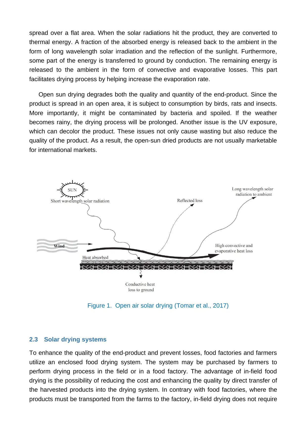
spread over a flat area. When the solar radiations hit the product, they are converted to
thermal energy. A fraction of the absorbed energy is released back to the ambient in the
form of long wavelength solar irradiation and the reflection of the sunlight. Furthermore,
some part of the energy is transferred to ground by conduction. The remaining energy is
released to the ambient in the form of convective and evaporative losses. This part
facilitates drying process by helping increase the evaporation rate.
Open sun drying degrades both the quality and quantity of the end-product. Since the
product is spread in an open area, it is subject to consumption by birds, rats and insects.
More importantly, it might be contaminated by bacteria and spoiled. If the weather
becomes rainy, the drying process will be prolonged. Another issue is the UV exposure,
which can decolor the product. These issues not only cause wasting but also reduce the
quality of the product. As a result, the open-sun dried products are not usually marketable
for international markets.
Figure 1. Open air solar drying (Tomar et al., 2017)
2.3 Solar drying systems
To enhance the quality of the end-product and prevent losses, food factories and farmers
utilize an enclosed food drying system. The system may be purchased by farmers to
perform drying process in the field or in a food factory. The advantage of in-field food
drying is the possibility of reducing the cost and enhancing the quality by direct transfer of
the harvested products into the drying system. In contrary with food factories, where the
products must be transported from the farms to the factory, in-field drying does not require
such transportation. However, the main disadvantage of in-field drying is that the drying
system is only used during the harvest season of the farm and remains idol during the rest
of the year. Therefore, only simple and cheap drying mechanisms are economically
justifiable for in-field applications.
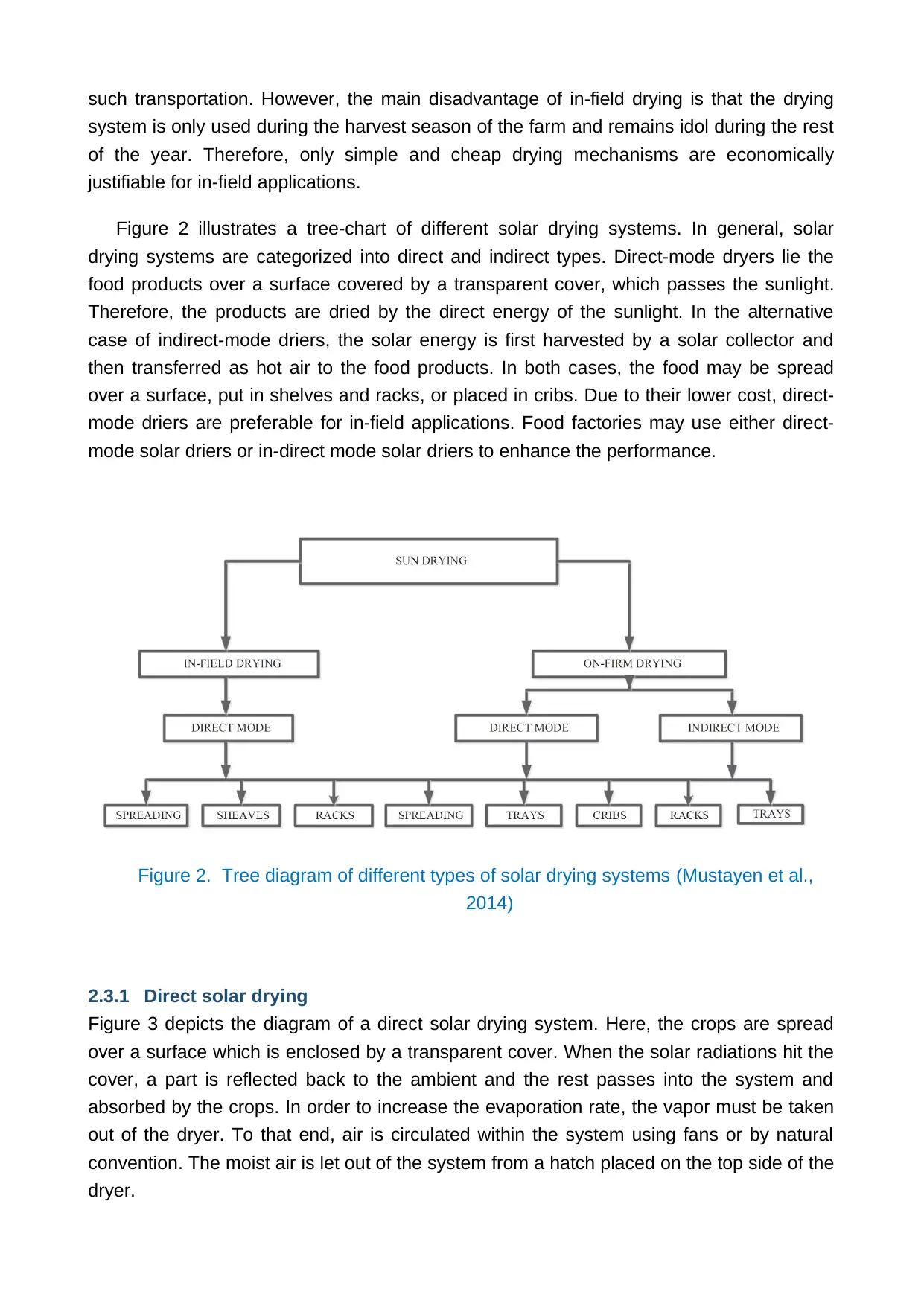
Figure 2 illustrates a tree-chart of different solar drying systems. In general, solar
drying systems are categorized into direct and indirect types. Direct-mode dryers lie the
food products over a surface covered by a transparent cover, which passes the sunlight.
Therefore, the products are dried by the direct energy of the sunlight. In the alternative
case of indirect-mode driers, the solar energy is first harvested by a solar collector and
then transferred as hot air to the food products. In both cases, the food may be spread
over a surface, put in shelves and racks, or placed in cribs. Due to their lower cost, direct-
mode driers are preferable for in-field applications. Food factories may use either direct-
mode solar driers or in-direct mode solar driers to enhance the performance.
Figure 2. Tree diagram of different types of solar drying systems (Mustayen et al.,
2014)
2.3.1 Direct solar drying
Figure 3 depicts the diagram of a direct solar drying system. Here, the crops are spread
over a surface which is enclosed by a transparent cover. When the solar radiations hit the
cover, a part is reflected back to the ambient and the rest passes into the system and
absorbed by the crops. In order to increase the evaporation rate, the vapor must be taken
out of the dryer. To that end, air is circulated within the system using fans or by natural
convention. The moist air is let out of the system from a hatch placed on the top side of the
dryer.
system is only used during the harvest season of the farm and remains idol during the rest
of the year. Therefore, only simple and cheap drying mechanisms are economically
justifiable for in-field applications.
Figure 2 illustrates a tree-chart of different solar drying systems. In general, solar
drying systems are categorized into direct and indirect types. Direct-mode dryers lie the
food products over a surface covered by a transparent cover, which passes the sunlight.
Therefore, the products are dried by the direct energy of the sunlight. In the alternative
case of indirect-mode driers, the solar energy is first harvested by a solar collector and
then transferred as hot air to the food products. In both cases, the food may be spread
over a surface, put in shelves and racks, or placed in cribs. Due to their lower cost, direct-
mode driers are preferable for in-field applications. Food factories may use either direct-
mode solar driers or in-direct mode solar driers to enhance the performance.
Figure 2. Tree diagram of different types of solar drying systems (Mustayen et al.,
2014)
2.3.1 Direct solar drying
Figure 3 depicts the diagram of a direct solar drying system. Here, the crops are spread
over a surface which is enclosed by a transparent cover. When the solar radiations hit the
cover, a part is reflected back to the ambient and the rest passes into the system and
absorbed by the crops. In order to increase the evaporation rate, the vapor must be taken
out of the dryer. To that end, air is circulated within the system using fans or by natural
convention. The moist air is let out of the system from a hatch placed on the top side of the
dryer.
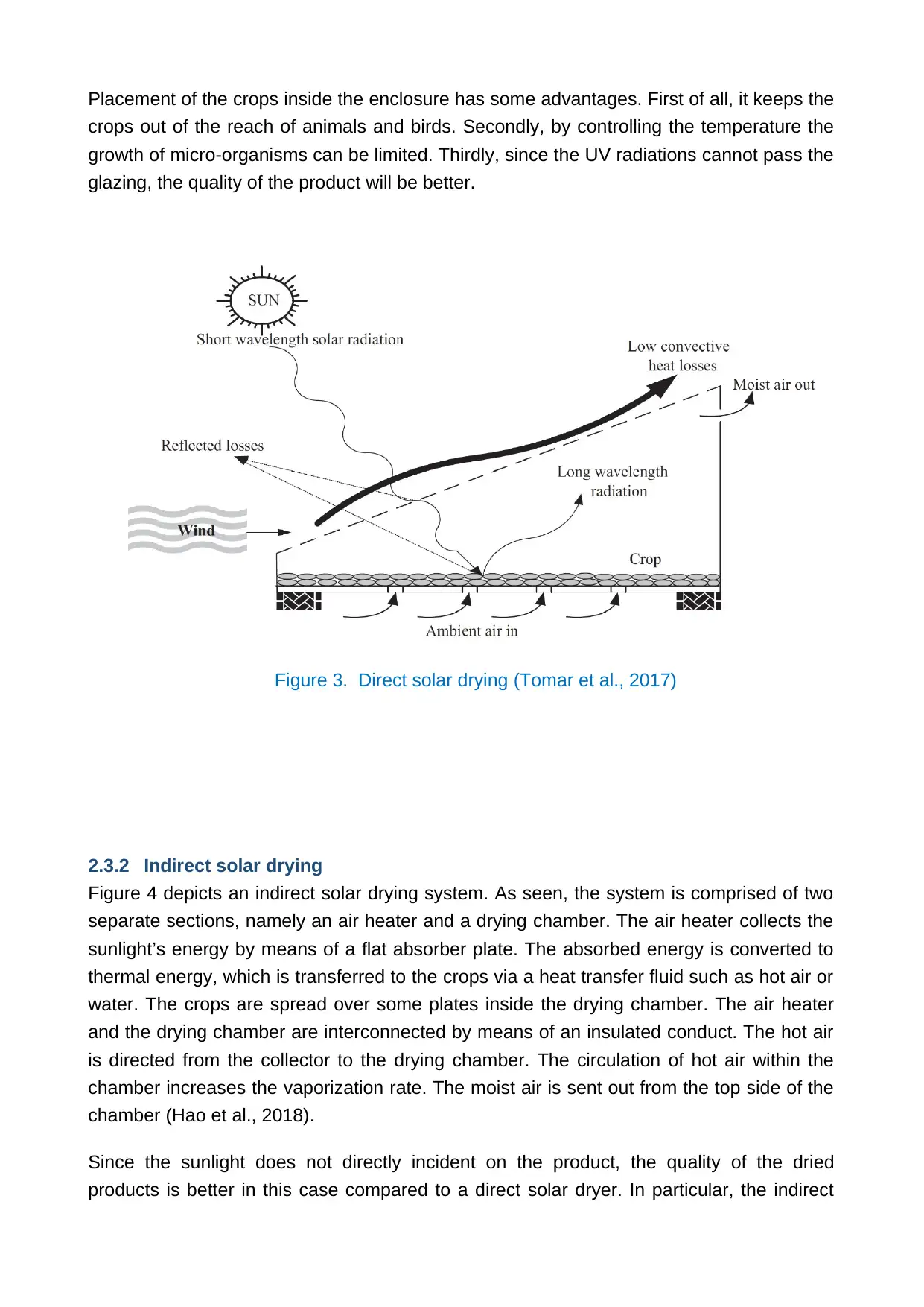
Placement of the crops inside the enclosure has some advantages. First of all, it keeps the
crops out of the reach of animals and birds. Secondly, by controlling the temperature the
growth of micro-organisms can be limited. Thirdly, since the UV radiations cannot pass the
glazing, the quality of the product will be better.
Figure 3. Direct solar drying (Tomar et al., 2017)
2.3.2 Indirect solar drying
Figure 4 depicts an indirect solar drying system. As seen, the system is comprised of two
separate sections, namely an air heater and a drying chamber. The air heater collects the
sunlight’s energy by means of a flat absorber plate. The absorbed energy is converted to
thermal energy, which is transferred to the crops via a heat transfer fluid such as hot air or
water. The crops are spread over some plates inside the drying chamber. The air heater
and the drying chamber are interconnected by means of an insulated conduct. The hot air
is directed from the collector to the drying chamber. The circulation of hot air within the
chamber increases the vaporization rate. The moist air is sent out from the top side of the
chamber (Hao et al., 2018).
Since the sunlight does not directly incident on the product, the quality of the dried
products is better in this case compared to a direct solar dryer. In particular, the indirect
Secure Best Marks with AI Grader
Need help grading? Try our AI Grader for instant feedback on your assignments.
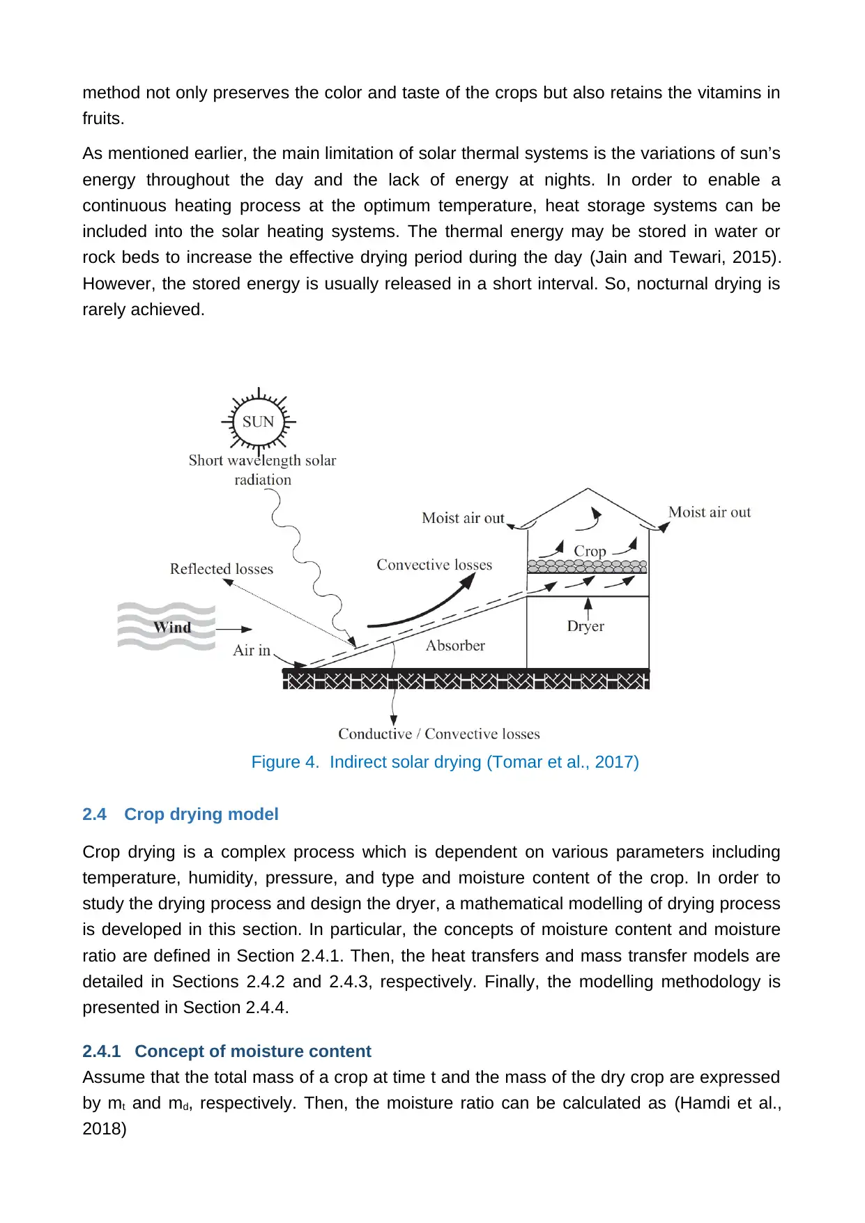
method not only preserves the color and taste of the crops but also retains the vitamins in
fruits.
As mentioned earlier, the main limitation of solar thermal systems is the variations of sun’s
energy throughout the day and the lack of energy at nights. In order to enable a
continuous heating process at the optimum temperature, heat storage systems can be
included into the solar heating systems. The thermal energy may be stored in water or
rock beds to increase the effective drying period during the day (Jain and Tewari, 2015).
However, the stored energy is usually released in a short interval. So, nocturnal drying is
rarely achieved.
Figure 4. Indirect solar drying (Tomar et al., 2017)
2.4 Crop drying model
Crop drying is a complex process which is dependent on various parameters including
temperature, humidity, pressure, and type and moisture content of the crop. In order to
study the drying process and design the dryer, a mathematical modelling of drying process
is developed in this section. In particular, the concepts of moisture content and moisture
ratio are defined in Section 2.4.1. Then, the heat transfers and mass transfer models are
detailed in Sections 2.4.2 and 2.4.3, respectively. Finally, the modelling methodology is
presented in Section 2.4.4.
2.4.1 Concept of moisture content
Assume that the total mass of a crop at time t and the mass of the dry crop are expressed
by mt and md, respectively. Then, the moisture ratio can be calculated as (Hamdi et al.,
2018)
(1)
If the moisture content of the crop at time t is Mt, the initial moisture content is Mi and the
equilibrium moisture content is Me, the moisture ratio can be calculated as
(2)
It is worth mentioning that the equilibrium moisture content, i.e., the moisture content after
drying, is usually much smaller than the initial moisture content. So, equation (2) can be
approximated as Mt / Mi . The drying rate is defined as the rate of change of the moisture
content, as follows:
(3)
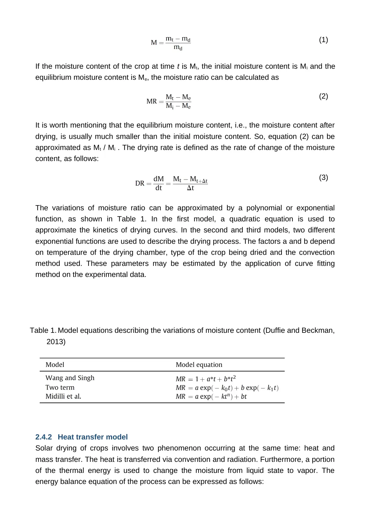
The variations of moisture ratio can be approximated by a polynomial or exponential
function, as shown in Table 1. In the first model, a quadratic equation is used to
approximate the kinetics of drying curves. In the second and third models, two different
exponential functions are used to describe the drying process. The factors a and b depend
on temperature of the drying chamber, type of the crop being dried and the convection
method used. These parameters may be estimated by the application of curve fitting
method on the experimental data.
Table 1. Model equations describing the variations of moisture content (Duffie and Beckman,
2013)
2.4.2 Heat transfer model
Solar drying of crops involves two phenomenon occurring at the same time: heat and
mass transfer. The heat is transferred via convention and radiation. Furthermore, a portion
of the thermal energy is used to change the moisture from liquid state to vapor. The
energy balance equation of the process can be expressed as follows:
If the moisture content of the crop at time t is Mt, the initial moisture content is Mi and the
equilibrium moisture content is Me, the moisture ratio can be calculated as
(2)
It is worth mentioning that the equilibrium moisture content, i.e., the moisture content after
drying, is usually much smaller than the initial moisture content. So, equation (2) can be
approximated as Mt / Mi . The drying rate is defined as the rate of change of the moisture
content, as follows:
(3)
The variations of moisture ratio can be approximated by a polynomial or exponential
function, as shown in Table 1. In the first model, a quadratic equation is used to
approximate the kinetics of drying curves. In the second and third models, two different
exponential functions are used to describe the drying process. The factors a and b depend
on temperature of the drying chamber, type of the crop being dried and the convection
method used. These parameters may be estimated by the application of curve fitting
method on the experimental data.
Table 1. Model equations describing the variations of moisture content (Duffie and Beckman,
2013)
2.4.2 Heat transfer model
Solar drying of crops involves two phenomenon occurring at the same time: heat and
mass transfer. The heat is transferred via convention and radiation. Furthermore, a portion
of the thermal energy is used to change the moisture from liquid state to vapor. The
energy balance equation of the process can be expressed as follows:
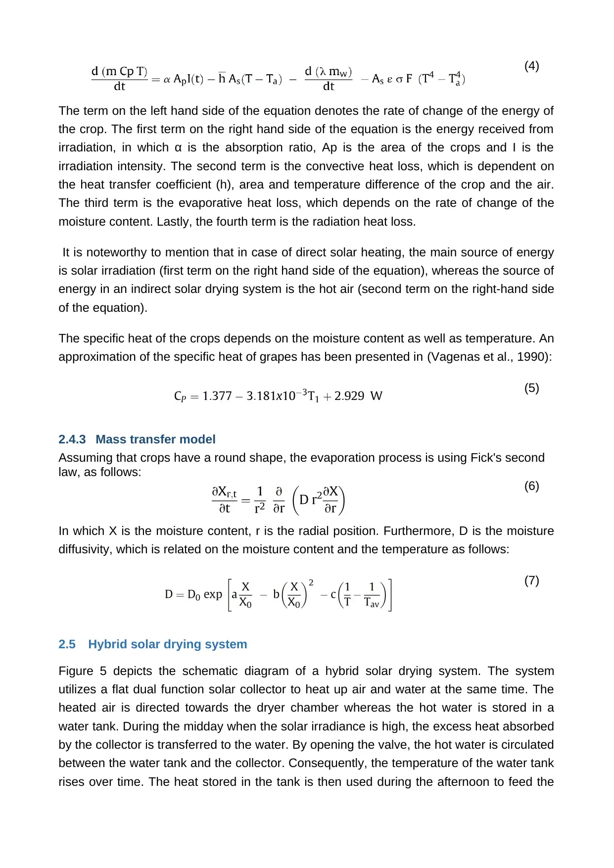
(4)
The term on the left hand side of the equation denotes the rate of change of the energy of
the crop. The first term on the right hand side of the equation is the energy received from
irradiation, in which α is the absorption ratio, Ap is the area of the crops and I is the
irradiation intensity. The second term is the convective heat loss, which is dependent on
the heat transfer coefficient (h), area and temperature difference of the crop and the air.
The third term is the evaporative heat loss, which depends on the rate of change of the
moisture content. Lastly, the fourth term is the radiation heat loss.
It is noteworthy to mention that in case of direct solar heating, the main source of energy
is solar irradiation (first term on the right hand side of the equation), whereas the source of
energy in an indirect solar drying system is the hot air (second term on the right-hand side
of the equation).
The specific heat of the crops depends on the moisture content as well as temperature. An
approximation of the specific heat of grapes has been presented in (Vagenas et al., 1990):
(5)
2.4.3 Mass transfer model
Assuming that crops have a round shape, the evaporation process is using Fick's second
law, as follows:
(6)
In which X is the moisture content, r is the radial position. Furthermore, D is the moisture
diffusivity, which is related on the moisture content and the temperature as follows:
(7)
2.5 Hybrid solar drying system
Figure 5 depicts the schematic diagram of a hybrid solar drying system. The system
utilizes a flat dual function solar collector to heat up air and water at the same time. The
heated air is directed towards the dryer chamber whereas the hot water is stored in a
water tank. During the midday when the solar irradiance is high, the excess heat absorbed
by the collector is transferred to the water. By opening the valve, the hot water is circulated
between the water tank and the collector. Consequently, the temperature of the water tank
rises over time. The heat stored in the tank is then used during the afternoon to feed the
Paraphrase This Document
Need a fresh take? Get an instant paraphrase of this document with our AI Paraphraser
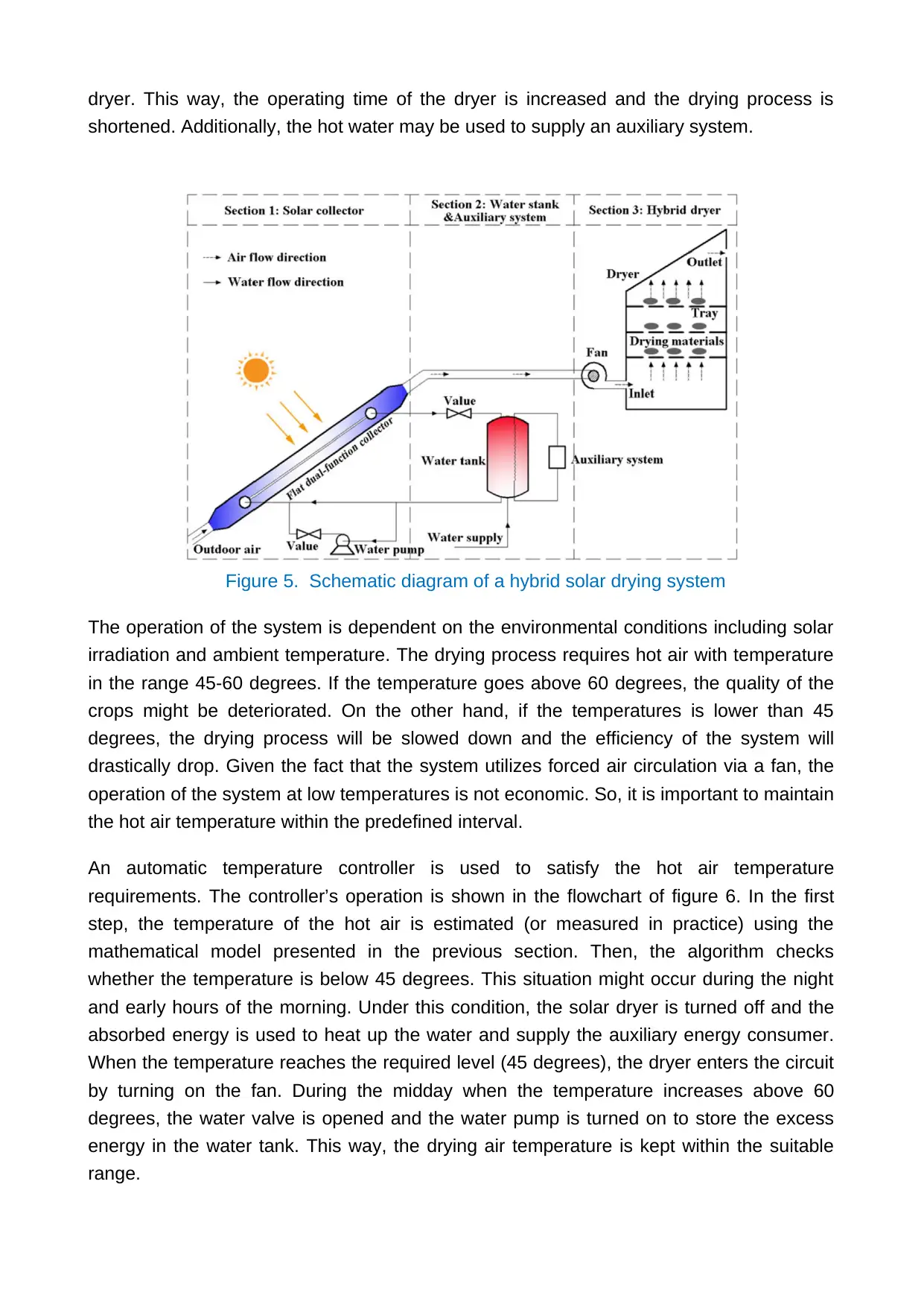
dryer. This way, the operating time of the dryer is increased and the drying process is
shortened. Additionally, the hot water may be used to supply an auxiliary system.
Figure 5. Schematic diagram of a hybrid solar drying system
The operation of the system is dependent on the environmental conditions including solar
irradiation and ambient temperature. The drying process requires hot air with temperature
in the range 45-60 degrees. If the temperature goes above 60 degrees, the quality of the
crops might be deteriorated. On the other hand, if the temperatures is lower than 45
degrees, the drying process will be slowed down and the efficiency of the system will
drastically drop. Given the fact that the system utilizes forced air circulation via a fan, the
operation of the system at low temperatures is not economic. So, it is important to maintain
the hot air temperature within the predefined interval.
An automatic temperature controller is used to satisfy the hot air temperature
requirements. The controller’s operation is shown in the flowchart of figure 6. In the first
step, the temperature of the hot air is estimated (or measured in practice) using the
mathematical model presented in the previous section. Then, the algorithm checks
whether the temperature is below 45 degrees. This situation might occur during the night
and early hours of the morning. Under this condition, the solar dryer is turned off and the
absorbed energy is used to heat up the water and supply the auxiliary energy consumer.
When the temperature reaches the required level (45 degrees), the dryer enters the circuit
by turning on the fan. During the midday when the temperature increases above 60
degrees, the water valve is opened and the water pump is turned on to store the excess
energy in the water tank. This way, the drying air temperature is kept within the suitable
range.
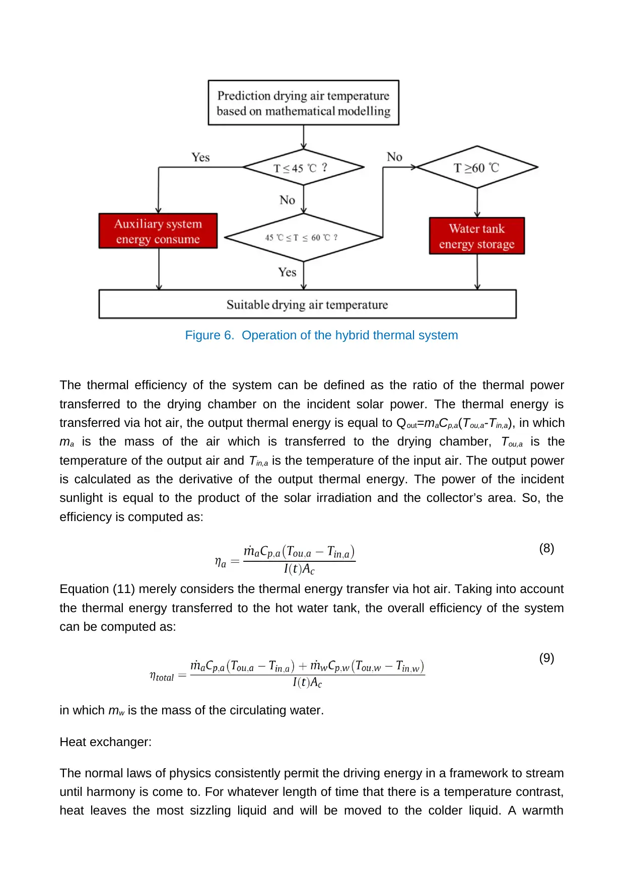
Figure 6. Operation of the hybrid thermal system
The thermal efficiency of the system can be defined as the ratio of the thermal power
transferred to the drying chamber on the incident solar power. The thermal energy is
transferred via hot air, the output thermal energy is equal to Qout=maCp,a(Tou,a-Tin,a), in which
ma is the mass of the air which is transferred to the drying chamber, Tou,a is the
temperature of the output air and Tin,a is the temperature of the input air. The output power
is calculated as the derivative of the output thermal energy. The power of the incident
sunlight is equal to the product of the solar irradiation and the collector’s area. So, the
efficiency is computed as:
(8)
Equation (11) merely considers the thermal energy transfer via hot air. Taking into account
the thermal energy transferred to the hot water tank, the overall efficiency of the system
can be computed as:
(9)
in which mw is the mass of the circulating water.
Heat exchanger:
The normal laws of physics consistently permit the driving energy in a framework to stream
until harmony is come to. For whatever length of time that there is a temperature contrast,
heat leaves the most sizzling liquid and will be moved to the colder liquid. A warmth
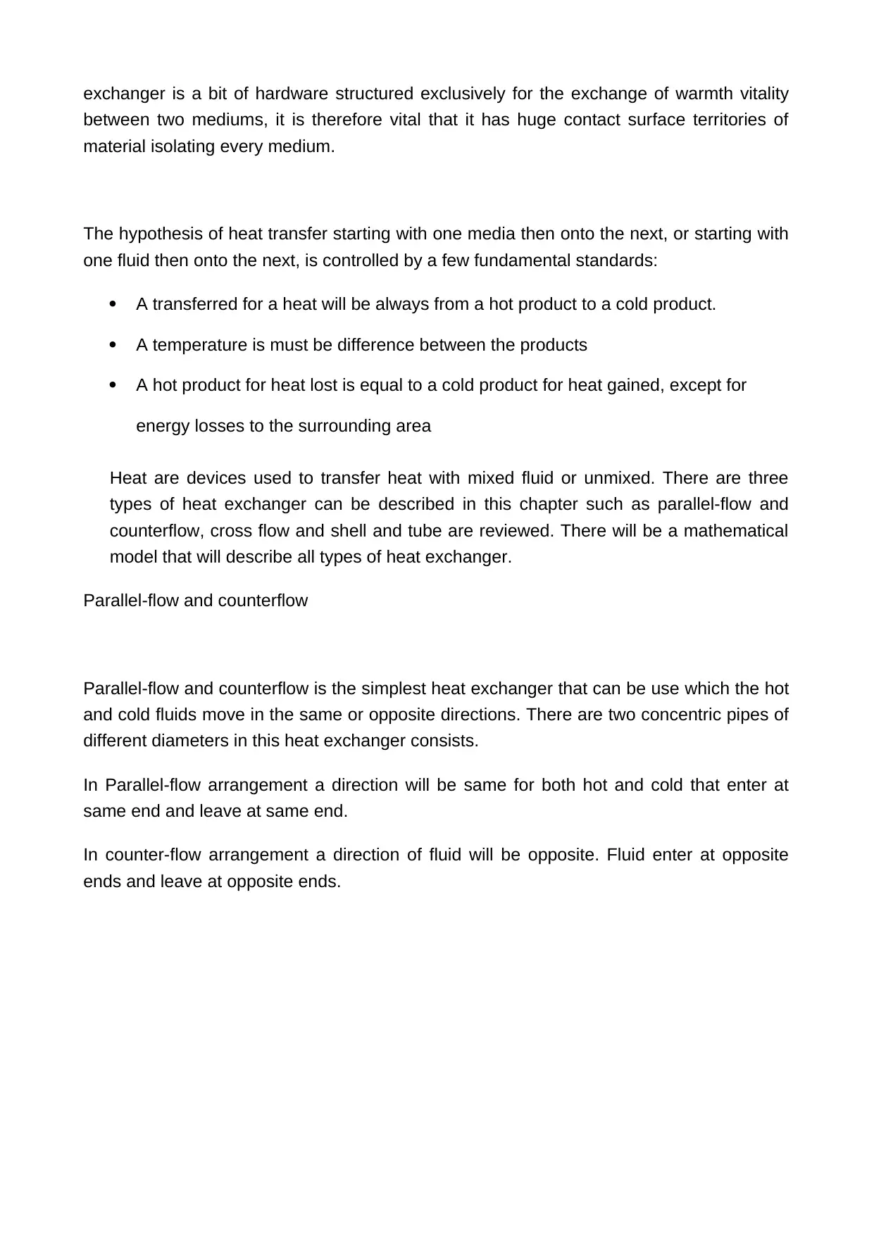
exchanger is a bit of hardware structured exclusively for the exchange of warmth vitality
between two mediums, it is therefore vital that it has huge contact surface territories of
material isolating every medium.
The hypothesis of heat transfer starting with one media then onto the next, or starting with
one fluid then onto the next, is controlled by a few fundamental standards:
A transferred for a heat will be always from a hot product to a cold product.
A temperature is must be difference between the products
A hot product for heat lost is equal to a cold product for heat gained, except for
energy losses to the surrounding area
Heat are devices used to transfer heat with mixed fluid or unmixed. There are three
types of heat exchanger can be described in this chapter such as parallel-flow and
counterflow, cross flow and shell and tube are reviewed. There will be a mathematical
model that will describe all types of heat exchanger.
Parallel-flow and counterflow
Parallel-flow and counterflow is the simplest heat exchanger that can be use which the hot
and cold fluids move in the same or opposite directions. There are two concentric pipes of
different diameters in this heat exchanger consists.
In Parallel-flow arrangement a direction will be same for both hot and cold that enter at
same end and leave at same end.
In counter-flow arrangement a direction of fluid will be opposite. Fluid enter at opposite
ends and leave at opposite ends.
Secure Best Marks with AI Grader
Need help grading? Try our AI Grader for instant feedback on your assignments.
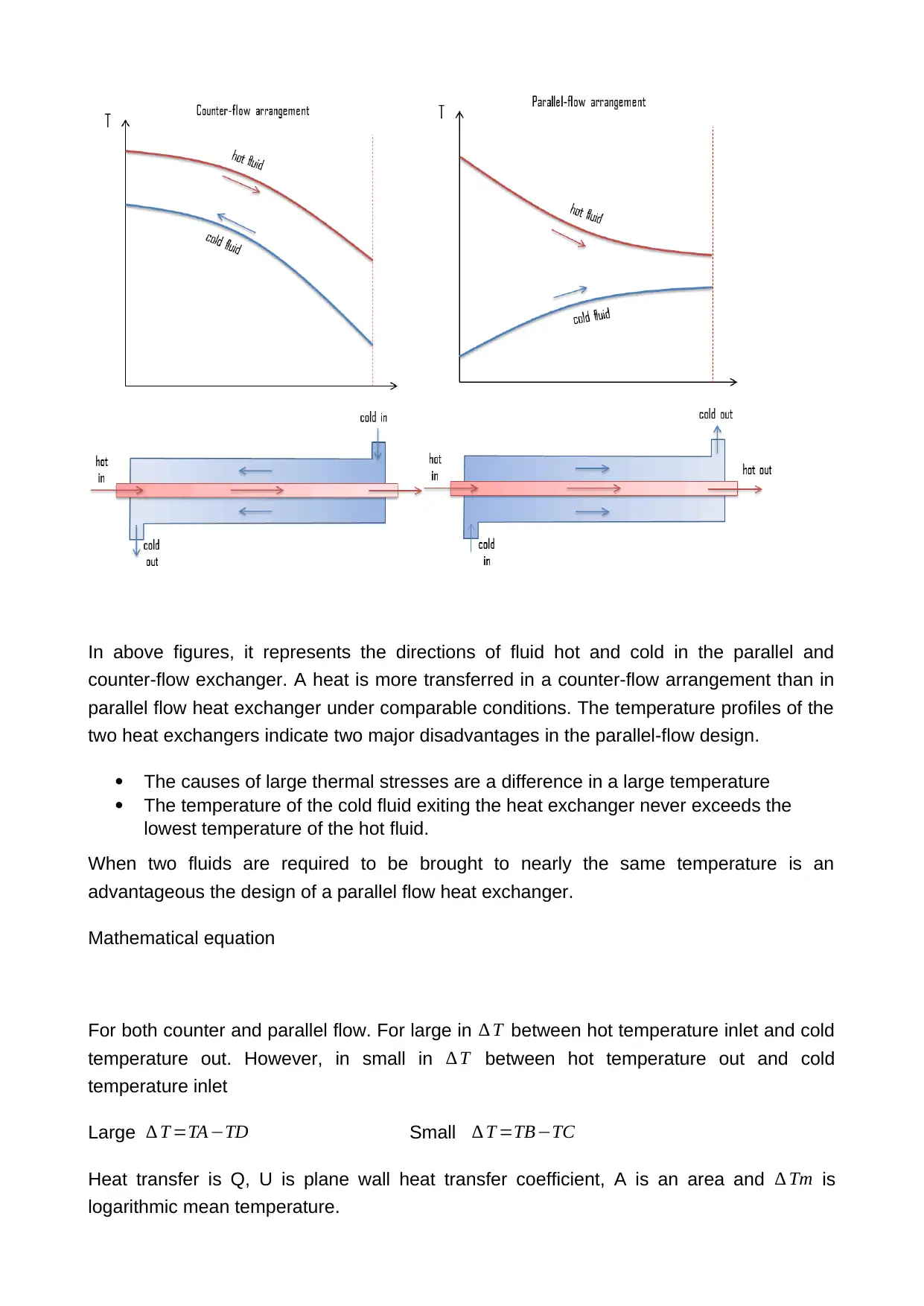
In above figures, it represents the directions of fluid hot and cold in the parallel and
counter-flow exchanger. A heat is more transferred in a counter-flow arrangement than in
parallel flow heat exchanger under comparable conditions. The temperature profiles of the
two heat exchangers indicate two major disadvantages in the parallel-flow design.
The causes of large thermal stresses are a difference in a large temperature
The temperature of the cold fluid exiting the heat exchanger never exceeds the
lowest temperature of the hot fluid.
When two fluids are required to be brought to nearly the same temperature is an
advantageous the design of a parallel flow heat exchanger.
Mathematical equation
For both counter and parallel flow. For large in ∆ T between hot temperature inlet and cold
temperature out. However, in small in ∆ T between hot temperature out and cold
temperature inlet
Large ∆ T =TA−TD Small ∆ T =TB−TC
Heat transfer is Q, U is plane wall heat transfer coefficient, A is an area and ∆ Tm is
logarithmic mean temperature.
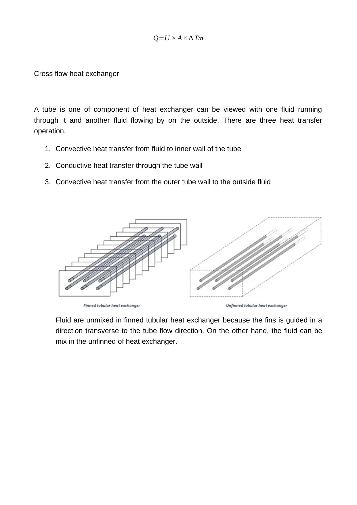
Q=U × A × ∆ Tm
Cross flow heat exchanger
A tube is one of component of heat exchanger can be viewed with one fluid running
through it and another fluid flowing by on the outside. There are three heat transfer
operation.
1. Convective heat transfer from fluid to inner wall of the tube
2. Conductive heat transfer through the tube wall
3. Convective heat transfer from the outer tube wall to the outside fluid
Fluid are unmixed in finned tubular heat exchanger because the fins is guided in a
direction transverse to the tube flow direction. On the other hand, the fluid can be
mix in the unfinned of heat exchanger.
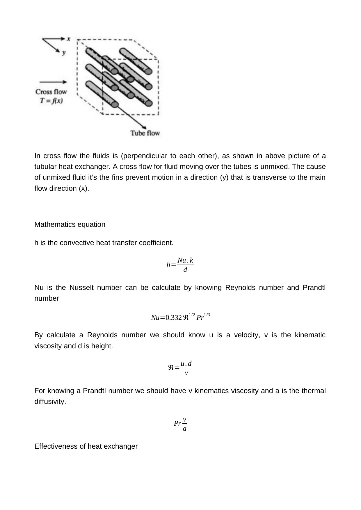
In cross flow the fluids is (perpendicular to each other), as shown in above picture of a
tubular heat exchanger. A cross flow for fluid moving over the tubes is unmixed. The cause
of unmixed fluid it’s the fins prevent motion in a direction (y) that is transverse to the main
flow direction (x).
Mathematics equation
h is the convective heat transfer coefficient.
h= Nu . k
d
Nu is the Nusselt number can be calculate by knowing Reynolds number and Prandtl
number
Nu=0.332 ℜ1 /2 Pr1 /3
By calculate a Reynolds number we should know u is a velocity, v is the kinematic
viscosity and d is height.
ℜ=u . d
v
For knowing a Prandtl number we should have v kinematics viscosity and a is the thermal
diffusivity.
Pr v
a
Effectiveness of heat exchanger
Paraphrase This Document
Need a fresh take? Get an instant paraphrase of this document with our AI Paraphraser
ε = actual heat transfer
maximum possible heat transfer
Shell and tube
Shell and tube are a most common types of heat exchanger by flexibility the designer that
has long range of temperature and pressure. It’s had two main categories:
1. It used in the petrochemical industry
2. It uses in the power industry for example feedwater heaters and power plant
condensers
Protection of nourishment and farming items is basic for nourishment security and
wellbeing. Improper strategies for protection and capacity achieve misfortunes of oats and
organic products going from 10% to 30% and a half to 70%, separately (Yaldyz and
Ertekyn, 2001). Drying or drying out is perhaps the most established system of
safeguarding utilized by mankind. The fundamental goal of the drying is to diminish the
dampness substance of nourishment and agrarian items to the sheltered stockpiling level
at which the items can be put away for a more drawn out period with no disintegration. The
low dampness substance averts the development of microorganisms, for example, molds,
microscopic organisms, and yeasts and decreases the synthetic responses falling apart
the nature of the items (Bahnasawy and Shenana, 2004). It likewise diminishes the weight
and volume of the items bringing about least bundling, stockpiling, and transportation costs
(Akpinar, 2006). In this way, the drying procedure avoids the deterioration of the
nourishment and horticultural items after gather and makes them accessible for the
utilization consistently.
Outside and uncontrolled sun drying is still, the most widely recognized technique used to
save and process Agricultural products.But uncontrolled drying experiences major issue of
wind conceived dust, pervasion by creepy-crawly, the item might be truly corrupted to the
degree that occasionally becomes showcase valueless and resultant loss of and needs to
the nourishment quality may have antagonistic financial impacts on household and
worldwide markets.
Dryers have been created and used to dry farming items to improve the timeframe of
realistic usability (Esper and Muhlbauer, 1996). A large portion of these either utilize a
costly wellspring of vitality, for example, power (ElShiatryet al., 1991) or a mix of sunlight
based vitality, what's more, some other type of vitality. Most undertakings of these nature
have not been embraced by the little ranchers, either because the last plan and
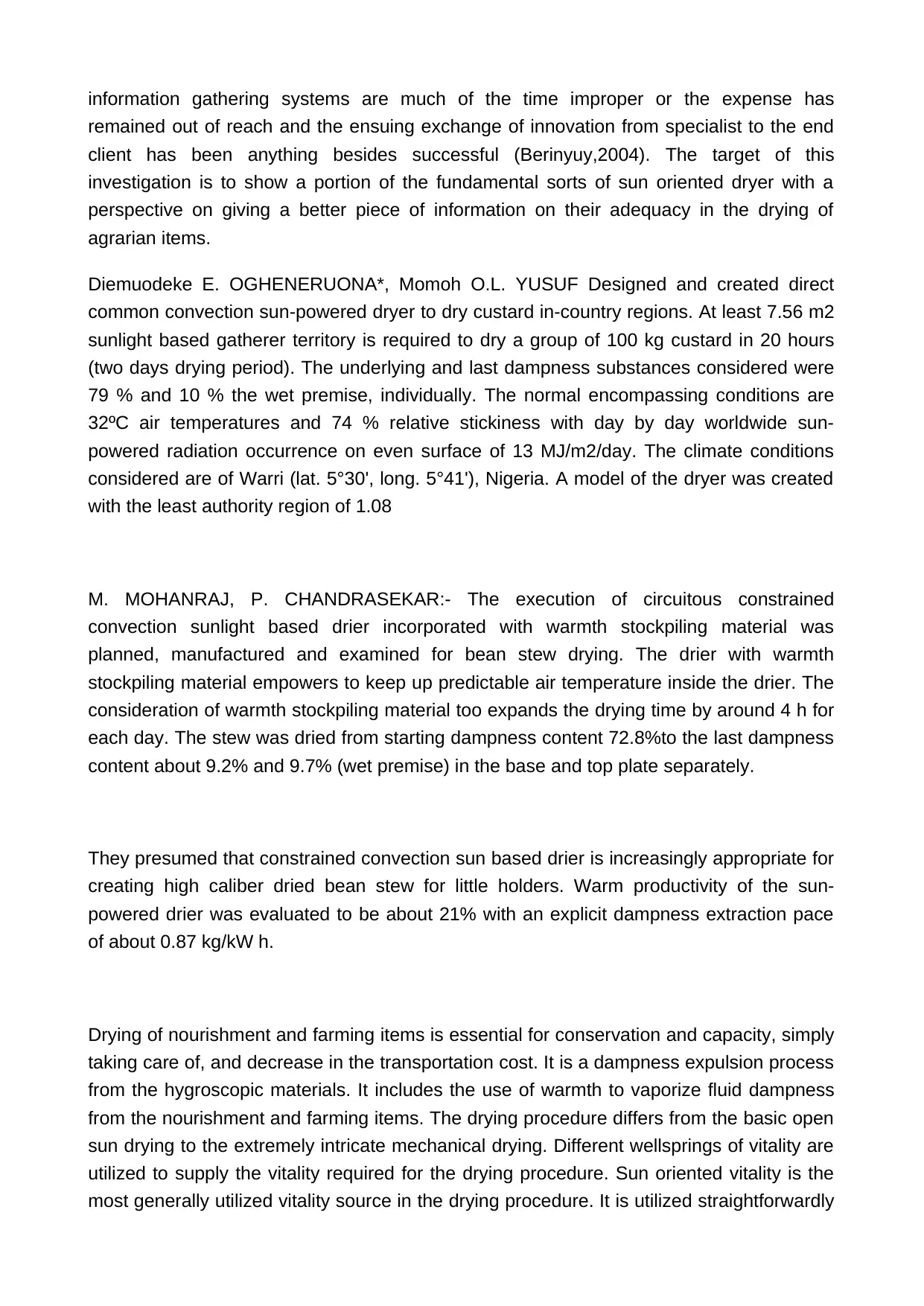
information gathering systems are much of the time improper or the expense has
remained out of reach and the ensuing exchange of innovation from specialist to the end
client has been anything besides successful (Berinyuy,2004). The target of this
investigation is to show a portion of the fundamental sorts of sun oriented dryer with a
perspective on giving a better piece of information on their adequacy in the drying of
agrarian items.
Diemuodeke E. OGHENERUONA*, Momoh O.L. YUSUF Designed and created direct
common convection sun-powered dryer to dry custard in-country regions. At least 7.56 m2
sunlight based gatherer territory is required to dry a group of 100 kg custard in 20 hours
(two days drying period). The underlying and last dampness substances considered were
79 % and 10 % the wet premise, individually. The normal encompassing conditions are
32ºC air temperatures and 74 % relative stickiness with day by day worldwide sun-
powered radiation occurrence on even surface of 13 MJ/m2/day. The climate conditions
considered are of Warri (lat. 5°30', long. 5°41'), Nigeria. A model of the dryer was created
with the least authority region of 1.08
M. MOHANRAJ, P. CHANDRASEKAR:- The execution of circuitous constrained
convection sunlight based drier incorporated with warmth stockpiling material was
planned, manufactured and examined for bean stew drying. The drier with warmth
stockpiling material empowers to keep up predictable air temperature inside the drier. The
consideration of warmth stockpiling material too expands the drying time by around 4 h for
each day. The stew was dried from starting dampness content 72.8%to the last dampness
content about 9.2% and 9.7% (wet premise) in the base and top plate separately.
They presumed that constrained convection sun based drier is increasingly appropriate for
creating high caliber dried bean stew for little holders. Warm productivity of the sun-
powered drier was evaluated to be about 21% with an explicit dampness extraction pace
of about 0.87 kg/kW h.
Drying of nourishment and farming items is essential for conservation and capacity, simply
taking care of, and decrease in the transportation cost. It is a dampness expulsion process
from the hygroscopic materials. It includes the use of warmth to vaporize fluid dampness
from the nourishment and farming items. The drying procedure differs from the basic open
sun drying to the extremely intricate mechanical drying. Different wellsprings of vitality are
utilized to supply the vitality required for the drying procedure. Sun oriented vitality is the
most generally utilized vitality source in the drying procedure. It is utilized straightforwardly
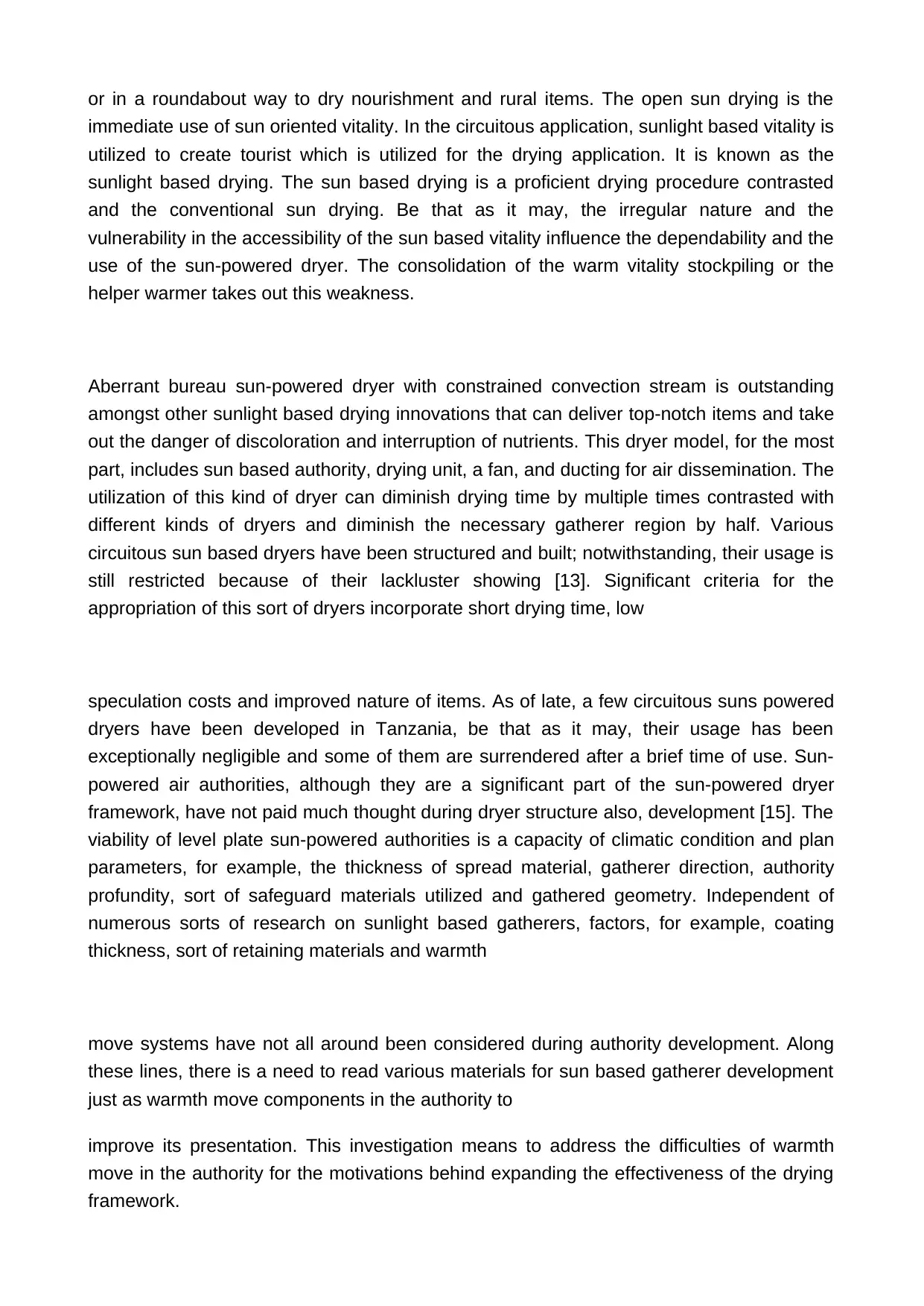
or in a roundabout way to dry nourishment and rural items. The open sun drying is the
immediate use of sun oriented vitality. In the circuitous application, sunlight based vitality is
utilized to create tourist which is utilized for the drying application. It is known as the
sunlight based drying. The sun based drying is a proficient drying procedure contrasted
and the conventional sun drying. Be that as it may, the irregular nature and the
vulnerability in the accessibility of the sun based vitality influence the dependability and the
use of the sun-powered dryer. The consolidation of the warm vitality stockpiling or the
helper warmer takes out this weakness.
Aberrant bureau sun-powered dryer with constrained convection stream is outstanding
amongst other sunlight based drying innovations that can deliver top-notch items and take
out the danger of discoloration and interruption of nutrients. This dryer model, for the most
part, includes sun based authority, drying unit, a fan, and ducting for air dissemination. The
utilization of this kind of dryer can diminish drying time by multiple times contrasted with
different kinds of dryers and diminish the necessary gatherer region by half. Various
circuitous sun based dryers have been structured and built; notwithstanding, their usage is
still restricted because of their lackluster showing [13]. Significant criteria for the
appropriation of this sort of dryers incorporate short drying time, low
speculation costs and improved nature of items. As of late, a few circuitous suns powered
dryers have been developed in Tanzania, be that as it may, their usage has been
exceptionally negligible and some of them are surrendered after a brief time of use. Sun-
powered air authorities, although they are a significant part of the sun-powered dryer
framework, have not paid much thought during dryer structure also, development [15]. The
viability of level plate sun-powered authorities is a capacity of climatic condition and plan
parameters, for example, the thickness of spread material, gatherer direction, authority
profundity, sort of safeguard materials utilized and gathered geometry. Independent of
numerous sorts of research on sunlight based gatherers, factors, for example, coating
thickness, sort of retaining materials and warmth
move systems have not all around been considered during authority development. Along
these lines, there is a need to read various materials for sun based gatherer development
just as warmth move components in the authority to
improve its presentation. This investigation means to address the difficulties of warmth
move in the authority for the motivations behind expanding the effectiveness of the drying
framework.
Secure Best Marks with AI Grader
Need help grading? Try our AI Grader for instant feedback on your assignments.
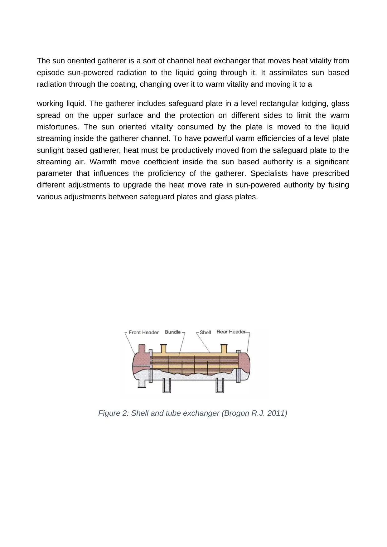
The sun oriented gatherer is a sort of channel heat exchanger that moves heat vitality from
episode sun-powered radiation to the liquid going through it. It assimilates sun based
radiation through the coating, changing over it to warm vitality and moving it to a
working liquid. The gatherer includes safeguard plate in a level rectangular lodging, glass
spread on the upper surface and the protection on different sides to limit the warm
misfortunes. The sun oriented vitality consumed by the plate is moved to the liquid
streaming inside the gatherer channel. To have powerful warm efficiencies of a level plate
sunlight based gatherer, heat must be productively moved from the safeguard plate to the
streaming air. Warmth move coefficient inside the sun based authority is a significant
parameter that influences the proficiency of the gatherer. Specialists have prescribed
different adjustments to upgrade the heat move rate in sun-powered authority by fusing
various adjustments between safeguard plates and glass plates.
Figure 2: Shell and tube exchanger (Brogon R.J. 2011)
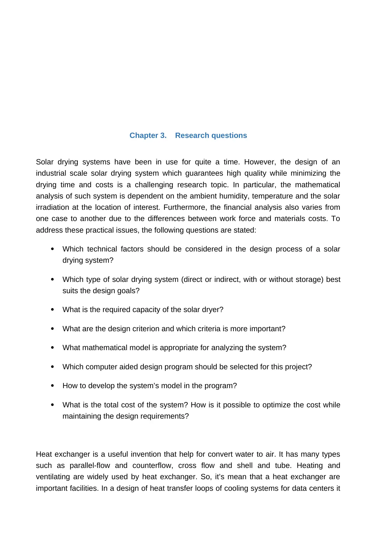
Chapter 3. Research questions
Solar drying systems have been in use for quite a time. However, the design of an
industrial scale solar drying system which guarantees high quality while minimizing the
drying time and costs is a challenging research topic. In particular, the mathematical
analysis of such system is dependent on the ambient humidity, temperature and the solar
irradiation at the location of interest. Furthermore, the financial analysis also varies from
one case to another due to the differences between work force and materials costs. To
address these practical issues, the following questions are stated:
Which technical factors should be considered in the design process of a solar
drying system?
Which type of solar drying system (direct or indirect, with or without storage) best
suits the design goals?
What is the required capacity of the solar dryer?
What are the design criterion and which criteria is more important?
What mathematical model is appropriate for analyzing the system?
Which computer aided design program should be selected for this project?
How to develop the system’s model in the program?
What is the total cost of the system? How is it possible to optimize the cost while
maintaining the design requirements?
Heat exchanger is a useful invention that help for convert water to air. It has many types
such as parallel-flow and counterflow, cross flow and shell and tube. Heating and
ventilating are widely used by heat exchanger. So, it’s mean that a heat exchanger are
important facilities. In a design of heat transfer loops of cooling systems for data centers it
needs to use a primary units of heat exchanger. A heat exchanger performance is strongly
influencing the thermal of the entire cooling system. An increasing interest in many
application areas it happens by transient phenomenon of heat exchanger. In cross flow
heat exchanger for a dynamic thermal model is solved numerically in order to predict the
transient response under step changes in the inlet temperature (Tianyi Gao 2015).
Which types of heat exchanger should be used?
How to design our heat exchanger and develop it?
How to measure an area of a heat exchanger?
What are they way to measure log mean temperature?
Chapter 4. Research Methodology
In this project, an indirect solar drying system is modelled and analyzed. The structure and
dimensions of the setup are adopted from the experimental setup implemented in (Hao et
al., 2018). This choice avails verification of the modelling and analysis results with the real
experimental results presented. The drying product is assumed to be sultana grapes. The
system’s specifications and mathematical modelling method are detailed in the following
text.
Paraphrase This Document
Need a fresh take? Get an instant paraphrase of this document with our AI Paraphraser
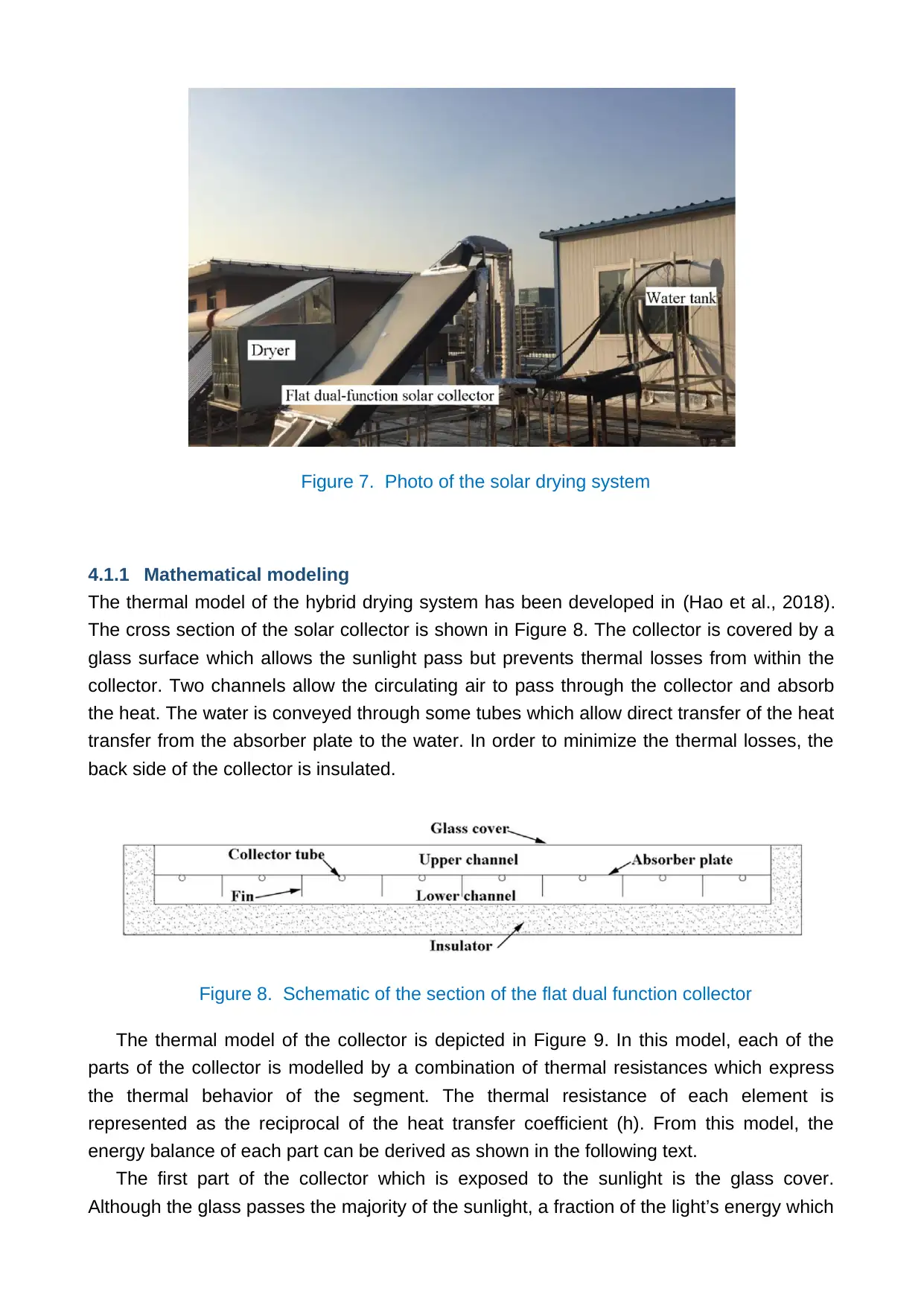
Figure 7. Photo of the solar drying system
4.1.1 Mathematical modeling
The thermal model of the hybrid drying system has been developed in (Hao et al., 2018).
The cross section of the solar collector is shown in Figure 8. The collector is covered by a
glass surface which allows the sunlight pass but prevents thermal losses from within the
collector. Two channels allow the circulating air to pass through the collector and absorb
the heat. The water is conveyed through some tubes which allow direct transfer of the heat
transfer from the absorber plate to the water. In order to minimize the thermal losses, the
back side of the collector is insulated.
Figure 8. Schematic of the section of the flat dual function collector
The thermal model of the collector is depicted in Figure 9. In this model, each of the
parts of the collector is modelled by a combination of thermal resistances which express
the thermal behavior of the segment. The thermal resistance of each element is
represented as the reciprocal of the heat transfer coefficient (h). From this model, the
energy balance of each part can be derived as shown in the following text.
The first part of the collector which is exposed to the sunlight is the glass cover.
Although the glass passes the majority of the sunlight, a fraction of the light’s energy which
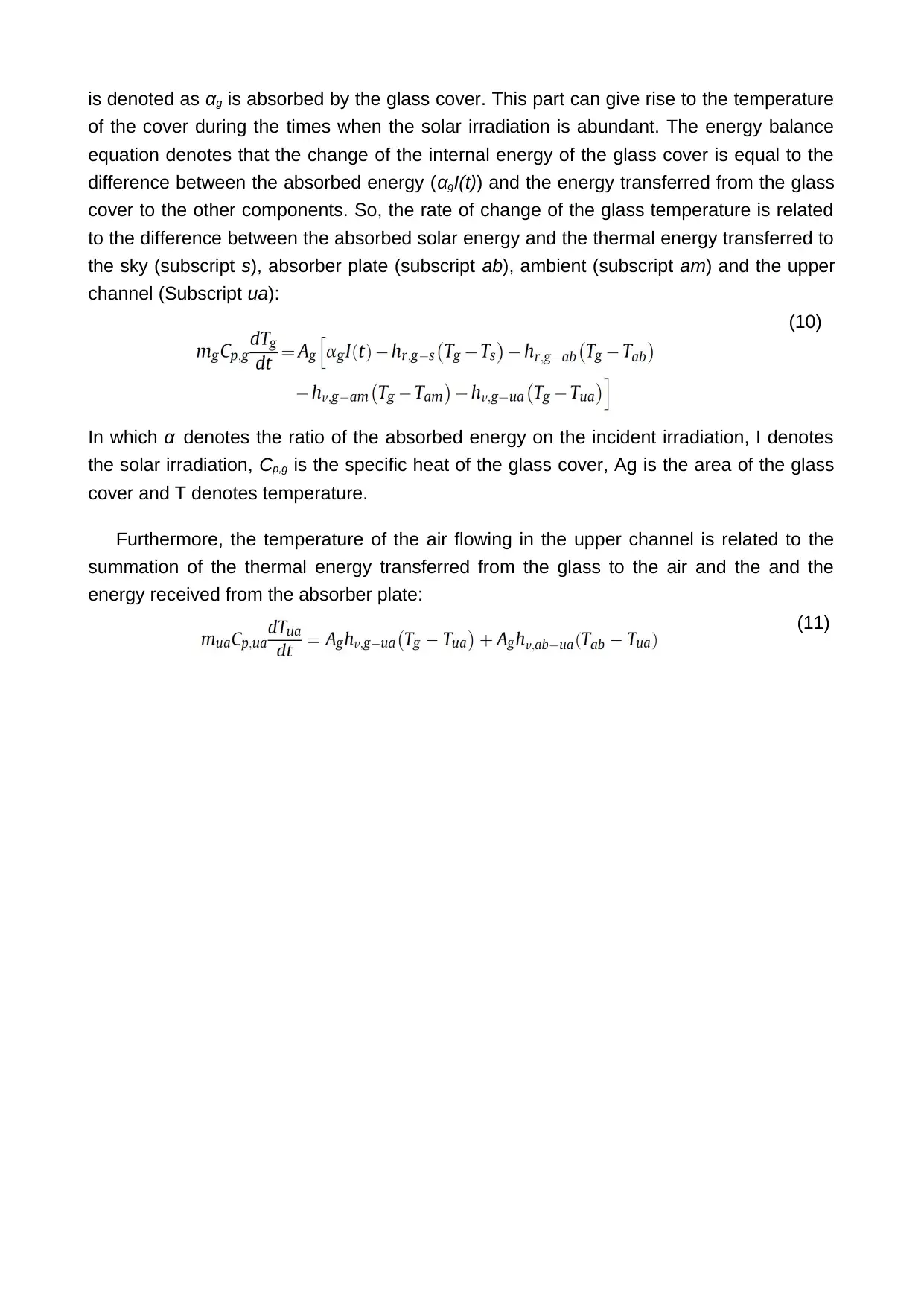
is denoted as αg is absorbed by the glass cover. This part can give rise to the temperature
of the cover during the times when the solar irradiation is abundant. The energy balance
equation denotes that the change of the internal energy of the glass cover is equal to the
difference between the absorbed energy (αgI(t)) and the energy transferred from the glass
cover to the other components. So, the rate of change of the glass temperature is related
to the difference between the absorbed solar energy and the thermal energy transferred to
the sky (subscript s), absorber plate (subscript ab), ambient (subscript am) and the upper
channel (Subscript ua):
(10)
In which α denotes the ratio of the absorbed energy on the incident irradiation, I denotes
the solar irradiation, Cp,g is the specific heat of the glass cover, Ag is the area of the glass
cover and T denotes temperature.
Furthermore, the temperature of the air flowing in the upper channel is related to the
summation of the thermal energy transferred from the glass to the air and the and the
energy received from the absorber plate:
(11)
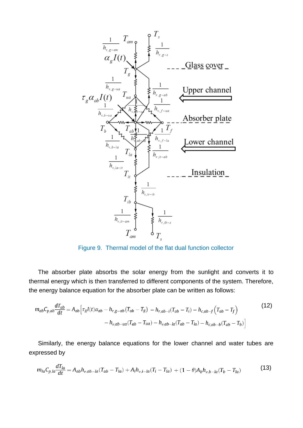
Figure 9. Thermal model of the flat dual function collector
The absorber plate absorbs the solar energy from the sunlight and converts it to
thermal energy which is then transferred to different components of the system. Therefore,
the energy balance equation for the absorber plate can be written as follows:
(12)
Similarly, the energy balance equations for the lower channel and water tubes are
expressed by
(13)
Secure Best Marks with AI Grader
Need help grading? Try our AI Grader for instant feedback on your assignments.
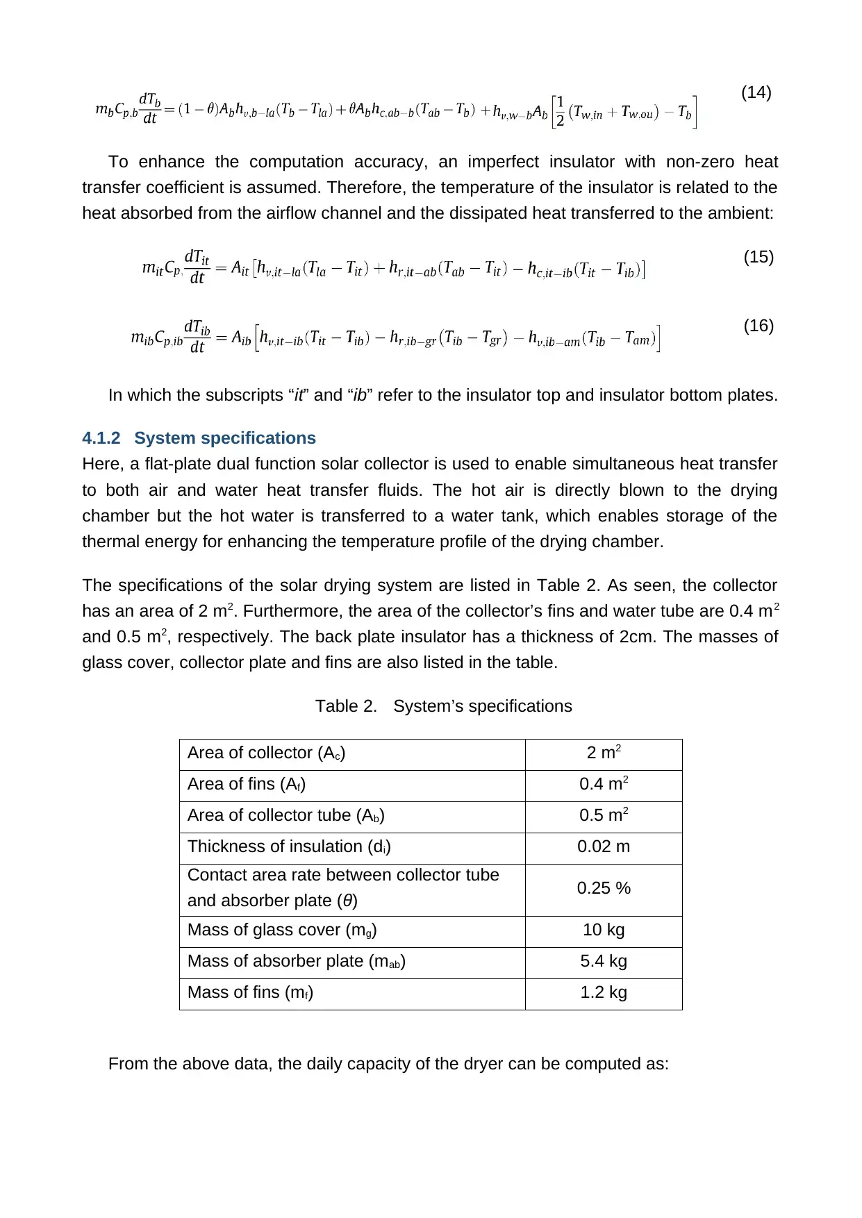
(14)
To enhance the computation accuracy, an imperfect insulator with non-zero heat
transfer coefficient is assumed. Therefore, the temperature of the insulator is related to the
heat absorbed from the airflow channel and the dissipated heat transferred to the ambient:
(15)
(16)
In which the subscripts “it” and “ib” refer to the insulator top and insulator bottom plates.
4.1.2 System specifications
Here, a flat-plate dual function solar collector is used to enable simultaneous heat transfer
to both air and water heat transfer fluids. The hot air is directly blown to the drying
chamber but the hot water is transferred to a water tank, which enables storage of the
thermal energy for enhancing the temperature profile of the drying chamber.
The specifications of the solar drying system are listed in Table 2. As seen, the collector
has an area of 2 m2. Furthermore, the area of the collector’s fins and water tube are 0.4 m2
and 0.5 m2, respectively. The back plate insulator has a thickness of 2cm. The masses of
glass cover, collector plate and fins are also listed in the table.
Table 2. System’s specifications
Area of collector (Ac) 2 m2
Area of fins (Af) 0.4 m2
Area of collector tube (Ab) 0.5 m2
Thickness of insulation (di) 0.02 m
Contact area rate between collector tube
and absorber plate (θ) 0.25 %
Mass of glass cover (mg) 10 kg
Mass of absorber plate (mab) 5.4 kg
Mass of fins (mf) 1.2 kg
From the above data, the daily capacity of the dryer can be computed as:
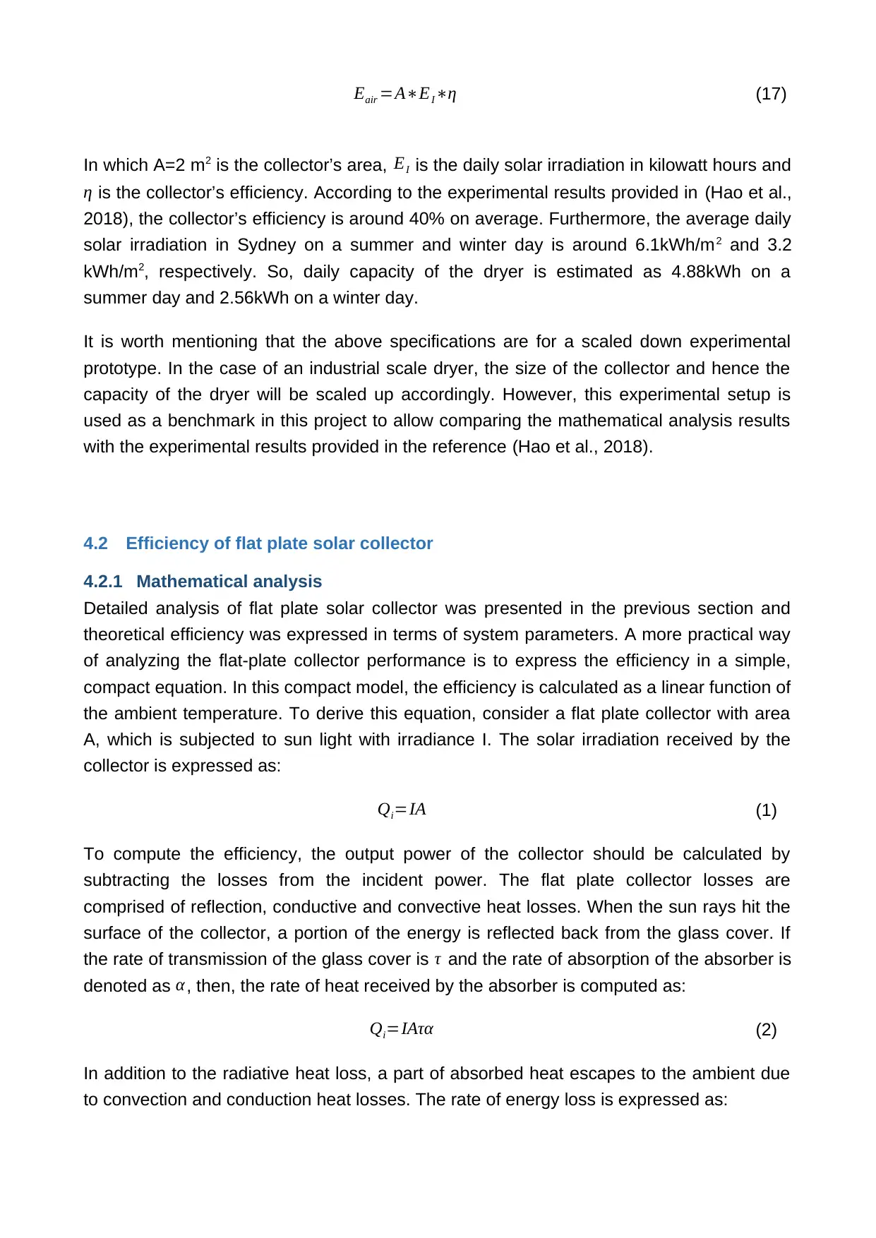
Eair =A∗EI∗η (17)
In which A=2 m2 is the collector’s area, EI is the daily solar irradiation in kilowatt hours and
η is the collector’s efficiency. According to the experimental results provided in (Hao et al.,
2018), the collector’s efficiency is around 40% on average. Furthermore, the average daily
solar irradiation in Sydney on a summer and winter day is around 6.1kWh/m2 and 3.2
kWh/m2, respectively. So, daily capacity of the dryer is estimated as 4.88kWh on a
summer day and 2.56kWh on a winter day.
It is worth mentioning that the above specifications are for a scaled down experimental
prototype. In the case of an industrial scale dryer, the size of the collector and hence the
capacity of the dryer will be scaled up accordingly. However, this experimental setup is
used as a benchmark in this project to allow comparing the mathematical analysis results
with the experimental results provided in the reference (Hao et al., 2018).
4.2 Efficiency of flat plate solar collector
4.2.1 Mathematical analysis
Detailed analysis of flat plate solar collector was presented in the previous section and
theoretical efficiency was expressed in terms of system parameters. A more practical way
of analyzing the flat-plate collector performance is to express the efficiency in a simple,
compact equation. In this compact model, the efficiency is calculated as a linear function of
the ambient temperature. To derive this equation, consider a flat plate collector with area
A, which is subjected to sun light with irradiance I. The solar irradiation received by the
collector is expressed as:
Qi=IA (1)
To compute the efficiency, the output power of the collector should be calculated by
subtracting the losses from the incident power. The flat plate collector losses are
comprised of reflection, conductive and convective heat losses. When the sun rays hit the
surface of the collector, a portion of the energy is reflected back from the glass cover. If
the rate of transmission of the glass cover is τ and the rate of absorption of the absorber is
denoted as α , then, the rate of heat received by the absorber is computed as:
Qi=IAτα (2)
In addition to the radiative heat loss, a part of absorbed heat escapes to the ambient due
to convection and conduction heat losses. The rate of energy loss is expressed as:
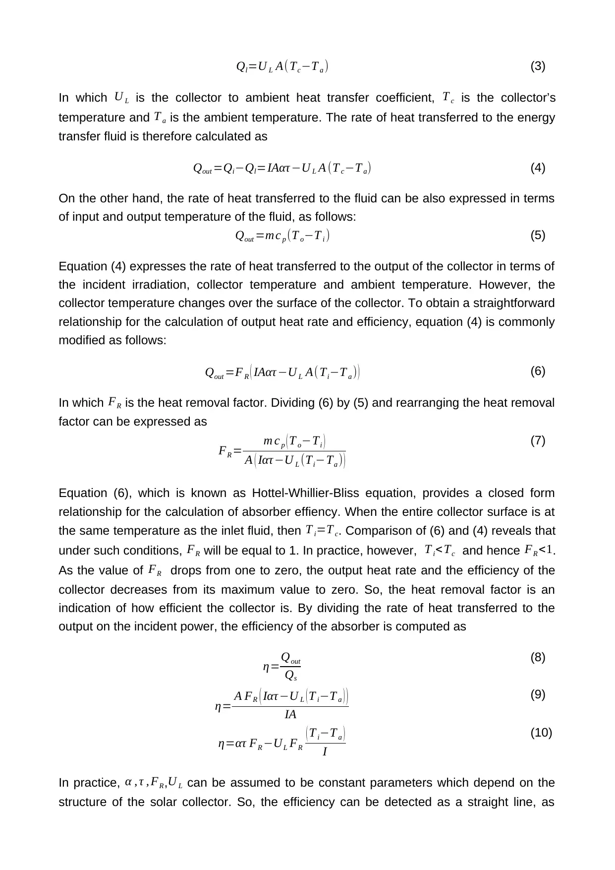
Ql=U L A( Tc−T a ) (3)
In which U L is the collector to ambient heat transfer coefficient, T c is the collector’s
temperature and T a is the ambient temperature. The rate of heat transferred to the energy
transfer fluid is therefore calculated as
Qout =Qi−Ql=IAατ −U L A (T c−T a) (4)
On the other hand, the rate of heat transferred to the fluid can be also expressed in terms
of input and output temperature of the fluid, as follows:
Qout =mc p (T o−T i ) (5)
Equation (4) expresses the rate of heat transferred to the output of the collector in terms of
the incident irradiation, collector temperature and ambient temperature. However, the
collector temperature changes over the surface of the collector. To obtain a straightforward
relationship for the calculation of output heat rate and efficiency, equation (4) is commonly
modified as follows:
Qout =F R ( IAατ −U L A(Ti−T a ) ) (6)
In which FR is the heat removal factor. Dividing (6) by (5) and rearranging the heat removal
factor can be expressed as
FR = m c p ( T o−Ti )
A ( Iατ −U L (Ti−Ta ) )
(7)
Equation (6), which is known as Hottel-Whillier-Bliss equation, provides a closed form
relationship for the calculation of absorber effiency. When the entire collector surface is at
the same temperature as the inlet fluid, then T i=T c. Comparison of (6) and (4) reveals that
under such conditions, FR will be equal to 1. In practice, however, T i<Tc and hence FR <1.
As the value of FR drops from one to zero, the output heat rate and the efficiency of the
collector decreases from its maximum value to zero. So, the heat removal factor is an
indication of how efficient the collector is. By dividing the rate of heat transferred to the
output on the incident power, the efficiency of the absorber is computed as
η=Qout
Qs
(8)
η= A FR ( Iατ −U L (T i−T a ) )
IA
(9)
η=ατ FR −UL FR
( T i−T a )
I
(10)
In practice, α , τ , FR,U L can be assumed to be constant parameters which depend on the
structure of the solar collector. So, the efficiency can be detected as a straight line, as
Paraphrase This Document
Need a fresh take? Get an instant paraphrase of this document with our AI Paraphraser
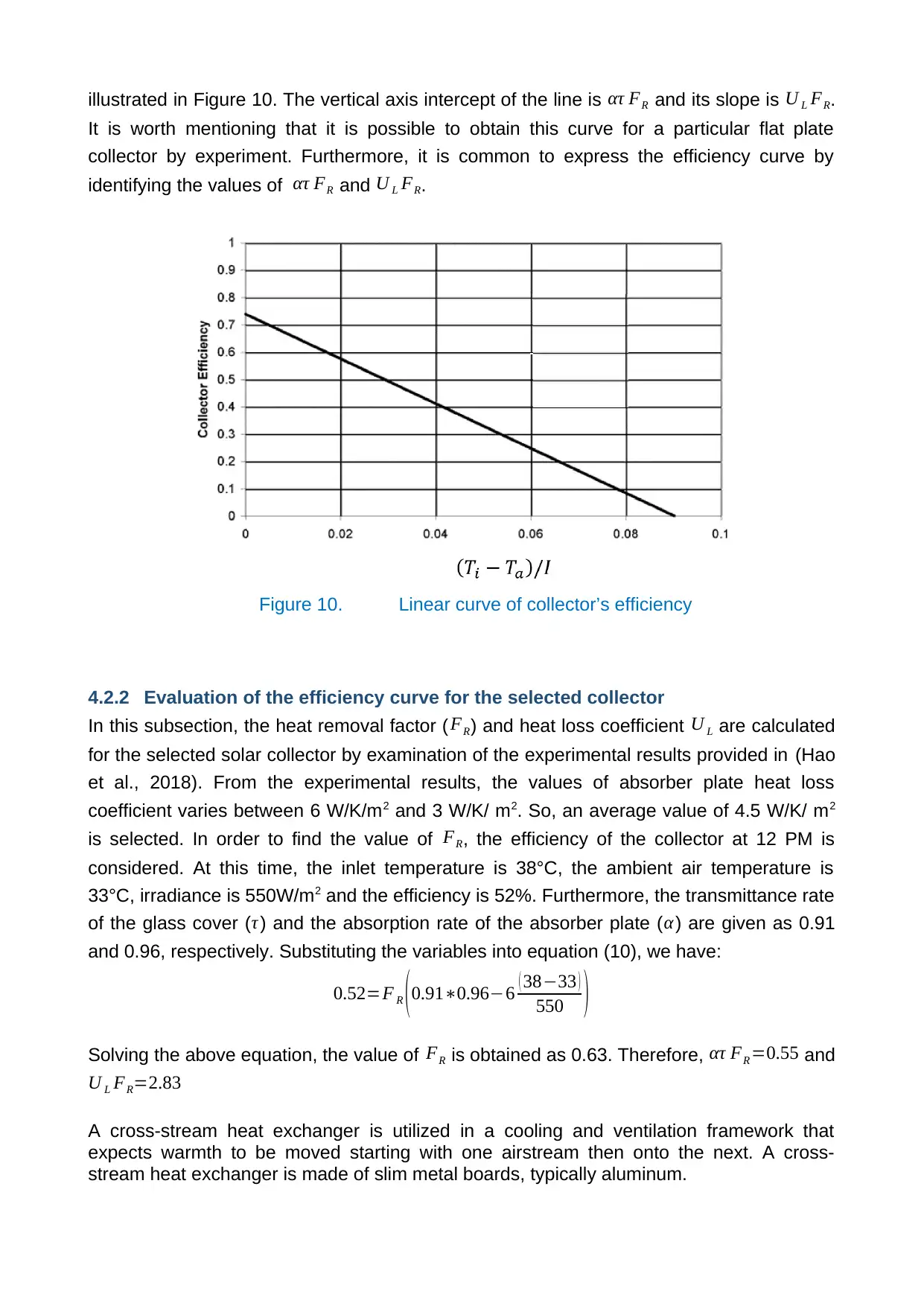
illustrated in Figure 10. The vertical axis intercept of the line is ατ FR and its slope is U L FR.
It is worth mentioning that it is possible to obtain this curve for a particular flat plate
collector by experiment. Furthermore, it is common to express the efficiency curve by
identifying the values of ατ FR and U L FR.
Figure 10. Linear curve of collector’s efficiency
4.2.2 Evaluation of the efficiency curve for the selected collector
In this subsection, the heat removal factor ( FR) and heat loss coefficient U L are calculated
for the selected solar collector by examination of the experimental results provided in (Hao
et al., 2018). From the experimental results, the values of absorber plate heat loss
coefficient varies between 6 W/K/m2 and 3 W/K/ m2. So, an average value of 4.5 W/K/ m2
is selected. In order to find the value of FR, the efficiency of the collector at 12 PM is
considered. At this time, the inlet temperature is 38°C, the ambient air temperature is
33°C, irradiance is 550W/m2 and the efficiency is 52%. Furthermore, the transmittance rate
of the glass cover ( τ ) and the absorption rate of the absorber plate ( α) are given as 0.91
and 0.96, respectively. Substituting the variables into equation (10), we have:
0.52=F R (0.91∗0.96−6 ( 38−33 )
550 )
Solving the above equation, the value of FR is obtained as 0.63. Therefore, ατ FR =0.55 and
U L FR=2.83
A cross-stream heat exchanger is utilized in a cooling and ventilation framework that
expects warmth to be moved starting with one airstream then onto the next. A cross-
stream heat exchanger is made of slim metal boards, typically aluminum.
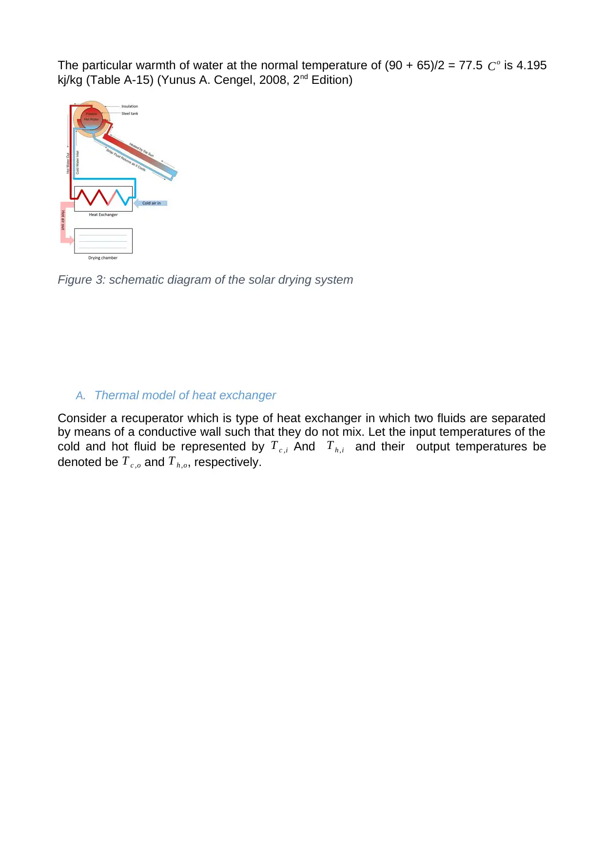
The particular warmth of water at the normal temperature of (90 + 65)/2 = 77.5 Co is 4.195
kj/kg (Table A-15) (Yunus A. Cengel, 2008, 2nd Edition)
Figure 3: schematic diagram of the solar drying system
A. Thermal model of heat exchanger
Consider a recuperator which is type of heat exchanger in which two fluids are separated
by means of a conductive wall such that they do not mix. Let the input temperatures of the
cold and hot fluid be represented by T c ,i And T h ,i and their output temperatures be
denoted be T c ,o and T h ,o, respectively.
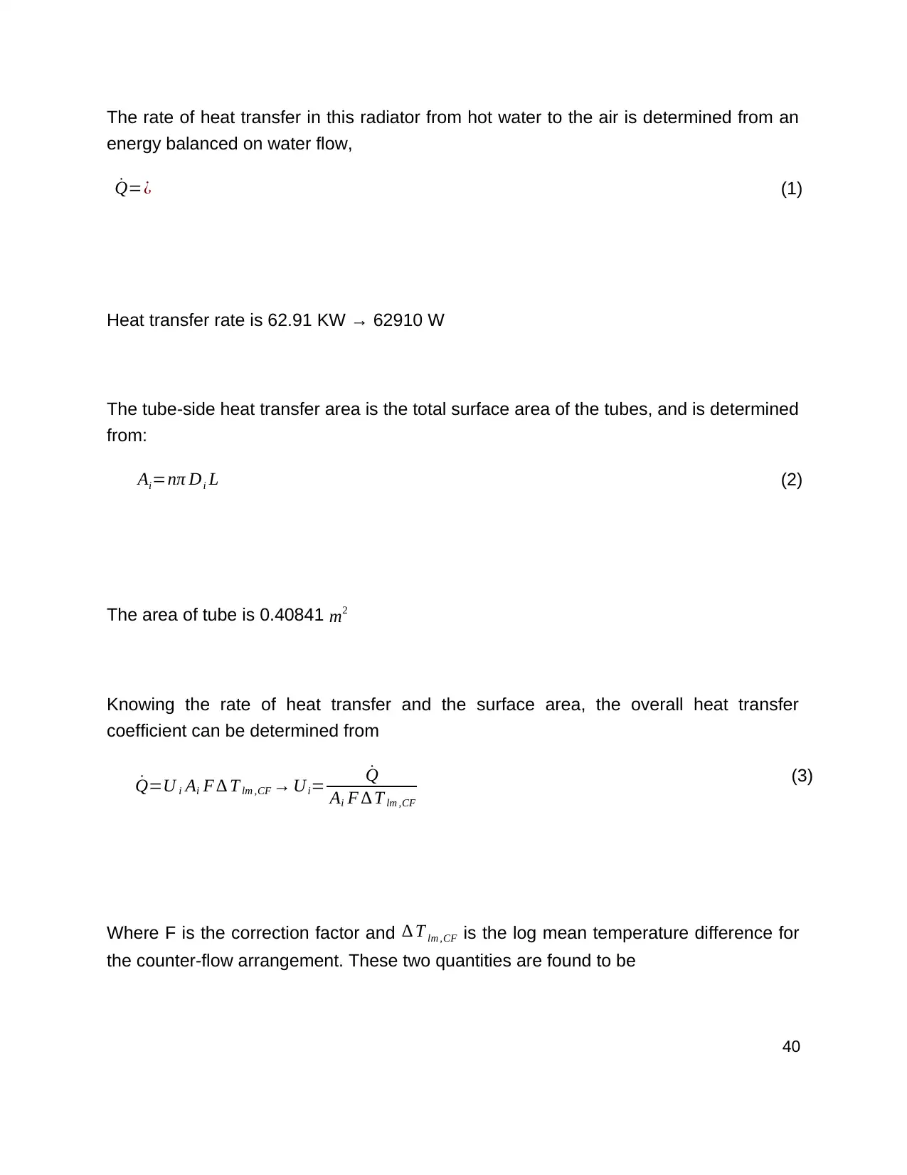
The rate of heat transfer in this radiator from hot water to the air is determined from an
energy balanced on water flow,
˙Q=¿ (1)
Heat transfer rate is 62.91 KW → 62910 W
The tube-side heat transfer area is the total surface area of the tubes, and is determined
from:
Ai=nπ Di L (2)
The area of tube is 0.40841 m2
Knowing the rate of heat transfer and the surface area, the overall heat transfer
coefficient can be determined from
˙Q=U i Ai F ∆ T lm ,CF → Ui= ˙Q
Ai F ∆ T lm ,CF
(3)
Where F is the correction factor and ∆ T lm ,CF is the log mean temperature difference for
the counter-flow arrangement. These two quantities are found to be
40
Secure Best Marks with AI Grader
Need help grading? Try our AI Grader for instant feedback on your assignments.
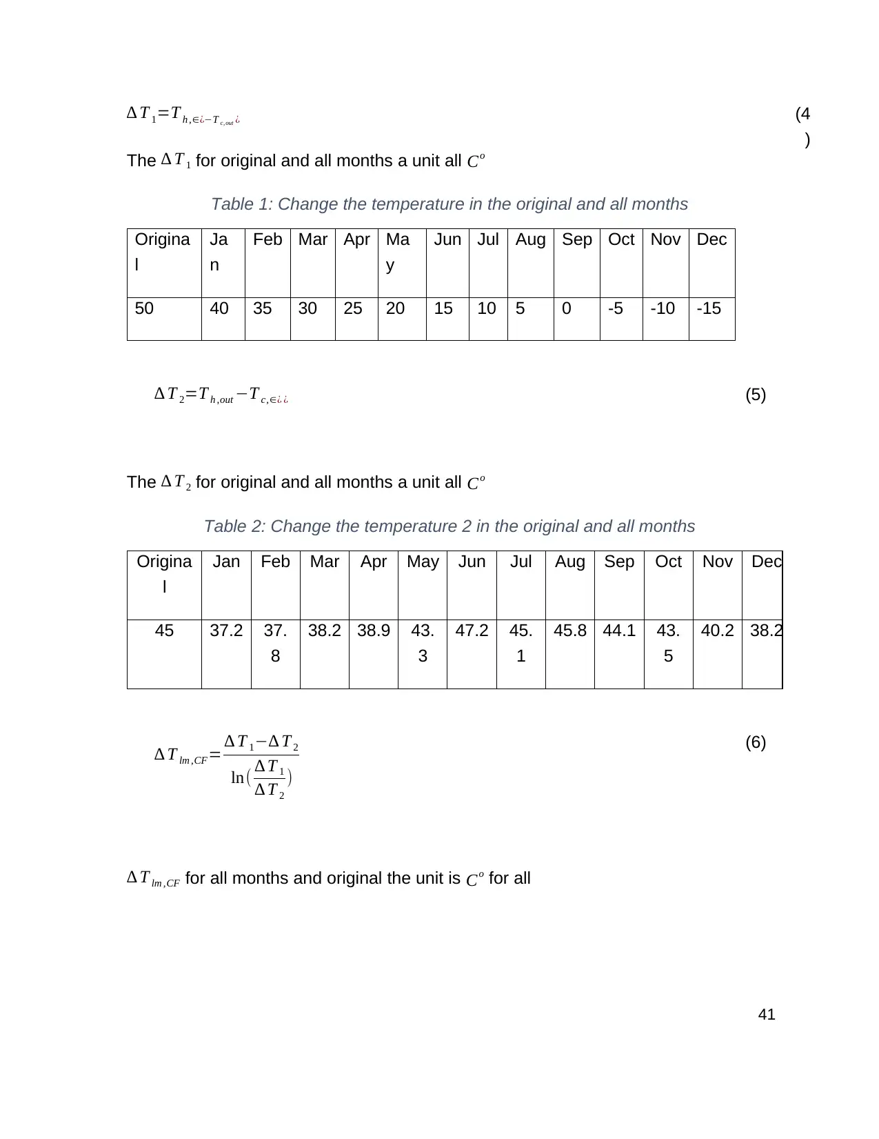
∆ T 1=T h ,∈¿−T c,out ¿
The ∆ T 1 for original and all months a unit all Co
Table 1: Change the temperature in the original and all months
Origina
l
Ja
n
Feb Mar Apr Ma
y
Jun Jul Aug Sep Oct Nov Dec
50 40 35 30 25 20 15 10 5 0 -5 -10 -15
∆ T 2=T h ,out −T c,∈¿ ¿ (5)
The ∆ T 2 for original and all months a unit all Co
Table 2: Change the temperature 2 in the original and all months
Origina
l
Jan Feb Mar Apr May Jun Jul Aug Sep Oct Nov Dec
45 37.2 37.
8
38.2 38.9 43.
3
47.2 45.
1
45.8 44.1 43.
5
40.2 38.2
∆ T lm ,CF= ∆ T 1−∆ T 2
ln( ∆ T 1
∆ T 2
)
(6)
∆ T lm ,CF for all months and original the unit is Co for all
(4
)
41
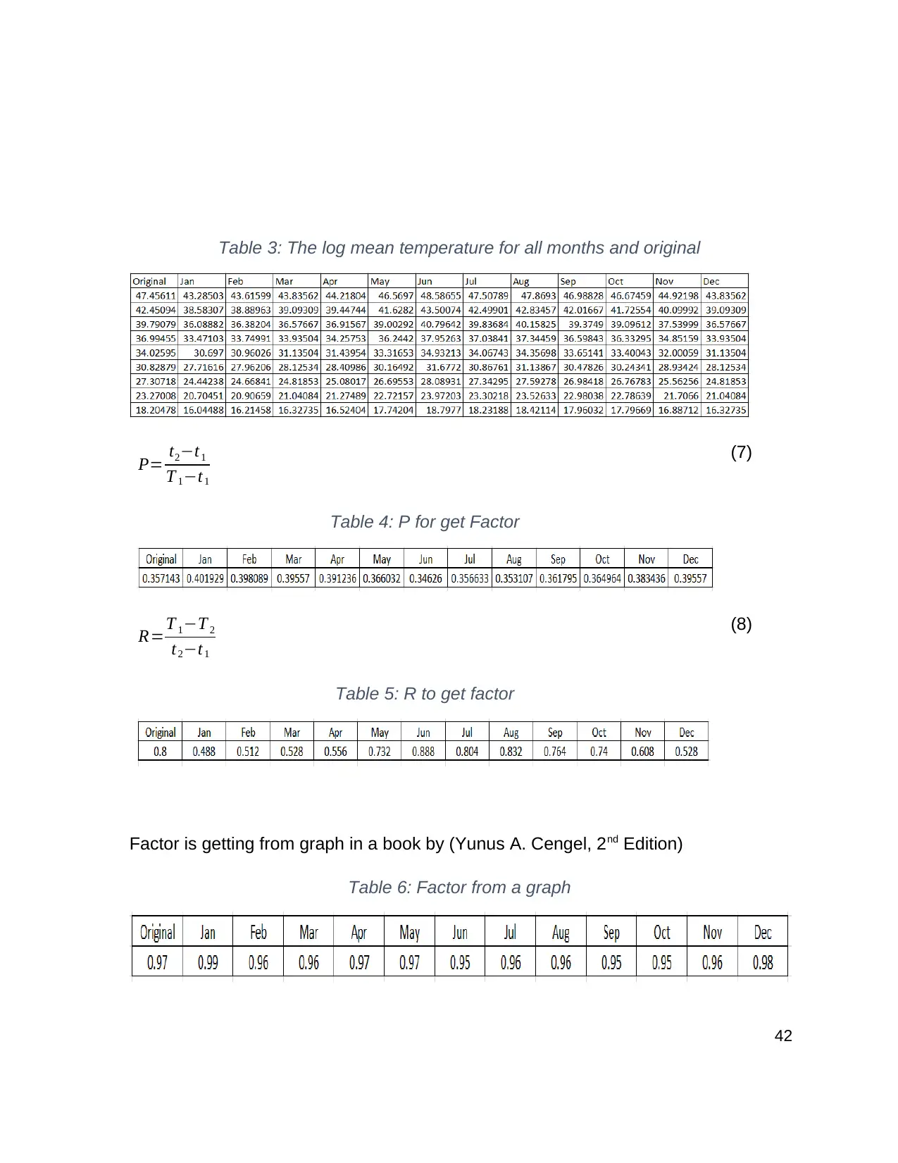
Table 3: The log mean temperature for all months and original
P= t2−t1
T 1−t1
Table 4: P for get Factor
(7)
R=T 1−T 2
t2−t1
Table 5: R to get factor
(8)
Factor is getting from graph in a book by (Yunus A. Cengel, 2nd Edition)
Table 6: Factor from a graph
42
P= t2−t1
T 1−t1
Table 4: P for get Factor
(7)
R=T 1−T 2
t2−t1
Table 5: R to get factor
(8)
Factor is getting from graph in a book by (Yunus A. Cengel, 2nd Edition)
Table 6: Factor from a graph
42
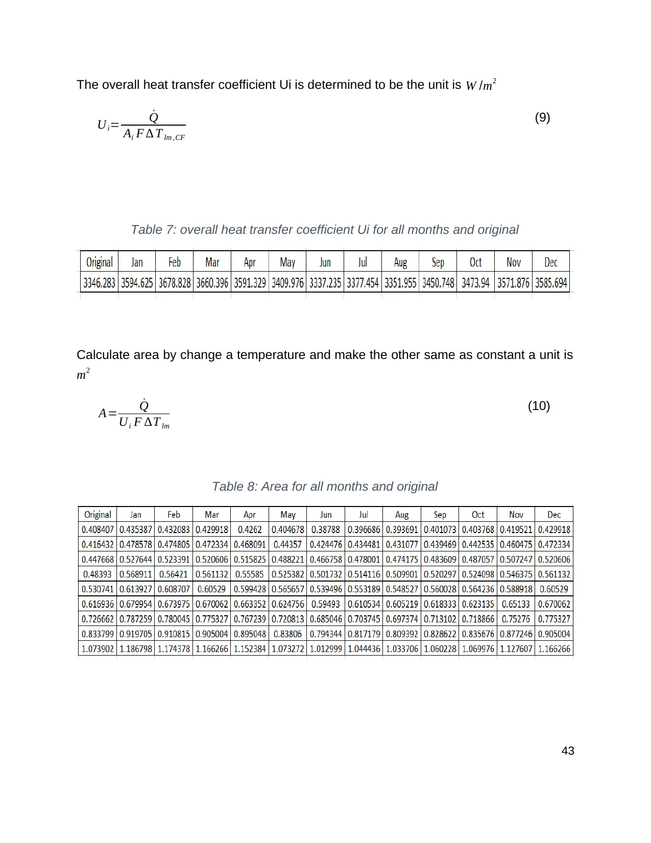
The overall heat transfer coefficient Ui is determined to be the unit is W /m2
Ui= ˙Q
Ai F ∆ T lm ,CF
(9)
Table 7: overall heat transfer coefficient Ui for all months and original
Calculate area by change a temperature and make the other same as constant a unit is
m2
A= ˙Q
Ui F ∆T lm
(10)
Table 8: Area for all months and original
43
Ui= ˙Q
Ai F ∆ T lm ,CF
(9)
Table 7: overall heat transfer coefficient Ui for all months and original
Calculate area by change a temperature and make the other same as constant a unit is
m2
A= ˙Q
Ui F ∆T lm
(10)
Table 8: Area for all months and original
43
Paraphrase This Document
Need a fresh take? Get an instant paraphrase of this document with our AI Paraphraser
Chapter 5. Data Collection
Two environmental variables are of key significance for analysis of the performance of
the solar drying system. The first and most important variable is the solar irradiance. As
shown in Chapter 4, the solar irradiance (I) appears as a key parameter which defines
the rate of heat transfer to the drying chamber and the temperature of the hot air.
Furthermore, the operating point of the system and its thermal efficiency is a function of
the ambient temperature. Therefore, it is important to have an accurate estimate of
these two key parameters.
The ambient temperature and solar irradiance at the location of interest (Sydney
observatory Hill, NSW, Australia) are acquired from Bureau of Meteorology (BoM).
Figure 11 shows the variations of solar irradiance on a sunny and a cloudy. From Figure
11 (a), it is seen that on a sunny day, the irradiance has a smooth bell shape curve with
a maximum of around 1100W/m2 at noon. Furthermore, the occasional shading caused
by passing of intermittent clouds caused irradiance to drop during some short intervals.
On the cloudy day (Figure 11 (b)), however, the variation of irradiance is significantly
affected by the shading of clouds. Moreover, the maximum irradiance is only 500 W/m2.
44
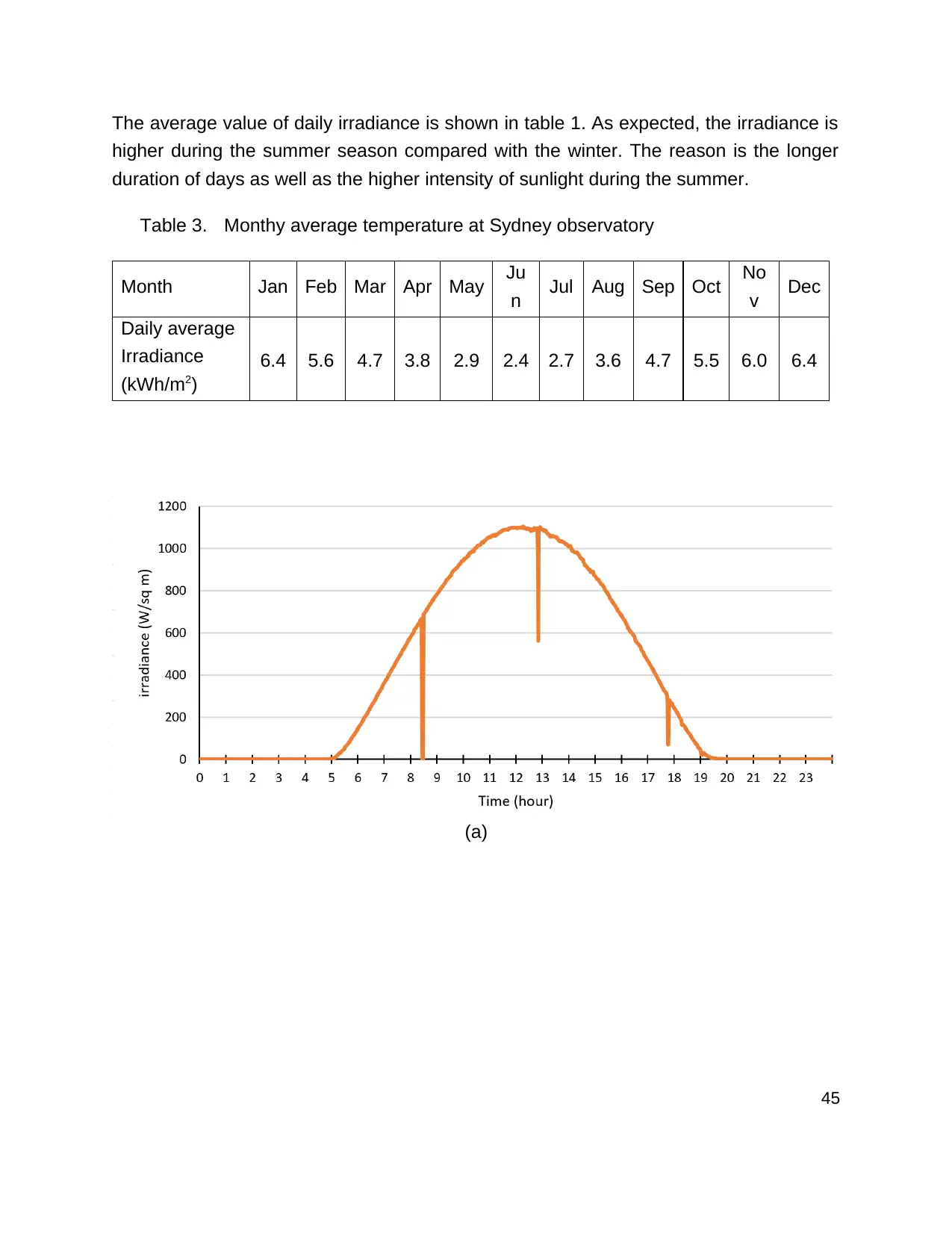
The average value of daily irradiance is shown in table 1. As expected, the irradiance is
higher during the summer season compared with the winter. The reason is the longer
duration of days as well as the higher intensity of sunlight during the summer.
Table 3. Monthy average temperature at Sydney observatory
Month Jan Feb Mar Apr May Ju
n Jul Aug Sep Oct No
v Dec
Daily average
Irradiance
(kWh/m2)
6.4 5.6 4.7 3.8 2.9 2.4 2.7 3.6 4.7 5.5 6.0 6.4
(a)
45
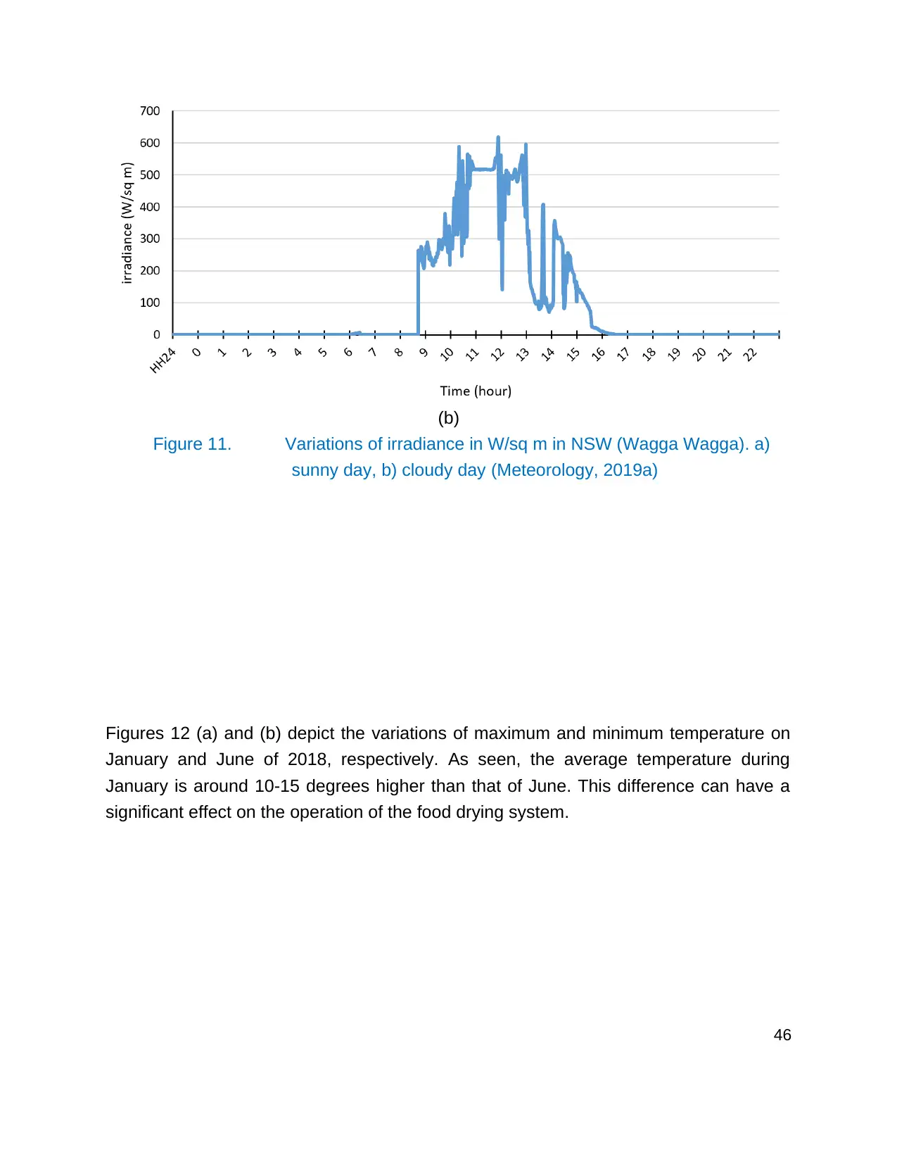
(b)
Figure 11. Variations of irradiance in W/sq m in NSW (Wagga Wagga). a)
sunny day, b) cloudy day (Meteorology, 2019a)
Figures 12 (a) and (b) depict the variations of maximum and minimum temperature on
January and June of 2018, respectively. As seen, the average temperature during
January is around 10-15 degrees higher than that of June. This difference can have a
significant effect on the operation of the food drying system.
46
Secure Best Marks with AI Grader
Need help grading? Try our AI Grader for instant feedback on your assignments.
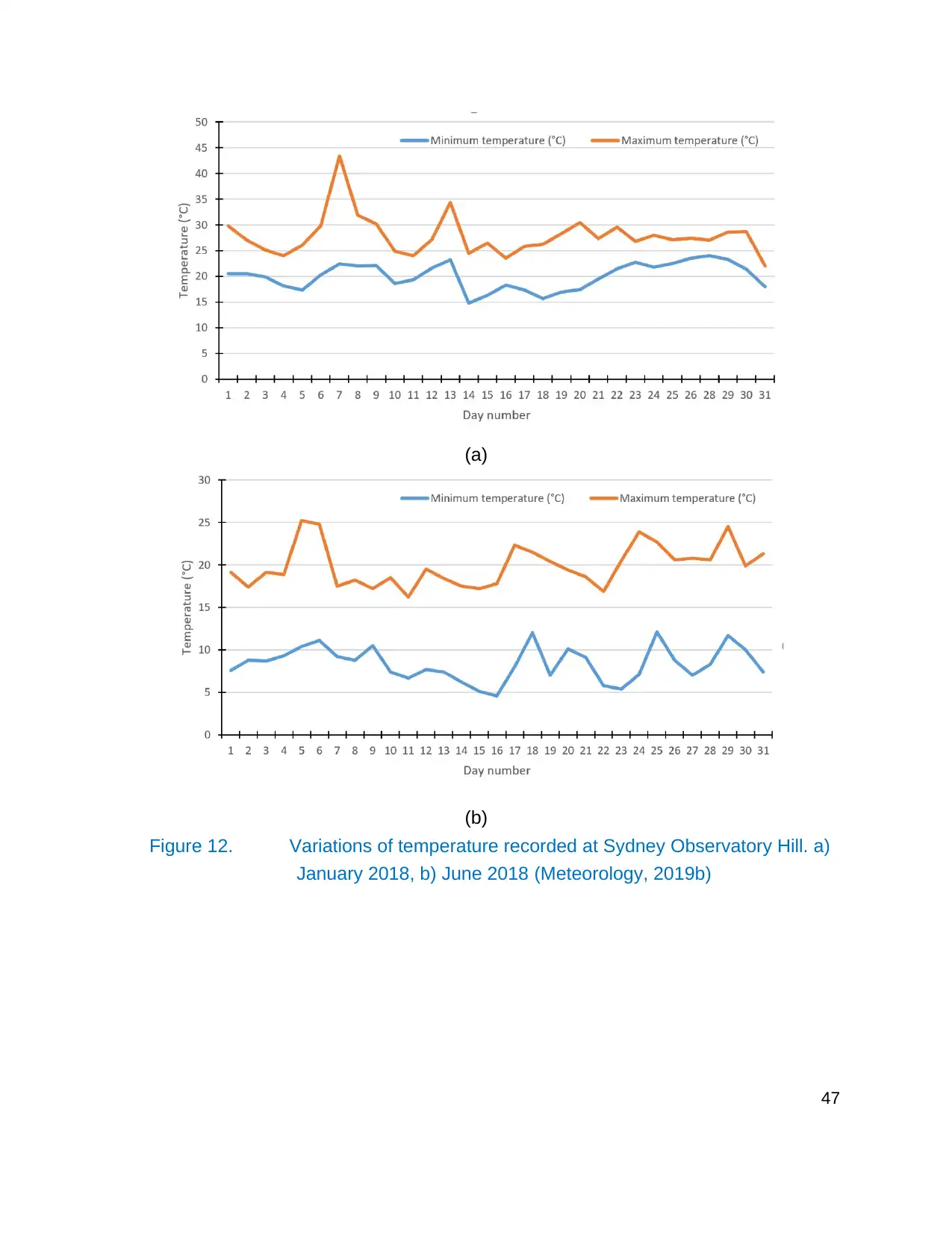
(a)
(b)
Figure 12. Variations of temperature recorded at Sydney Observatory Hill. a)
January 2018, b) June 2018 (Meteorology, 2019b)
47
(b)
Figure 12. Variations of temperature recorded at Sydney Observatory Hill. a)
January 2018, b) June 2018 (Meteorology, 2019b)
47
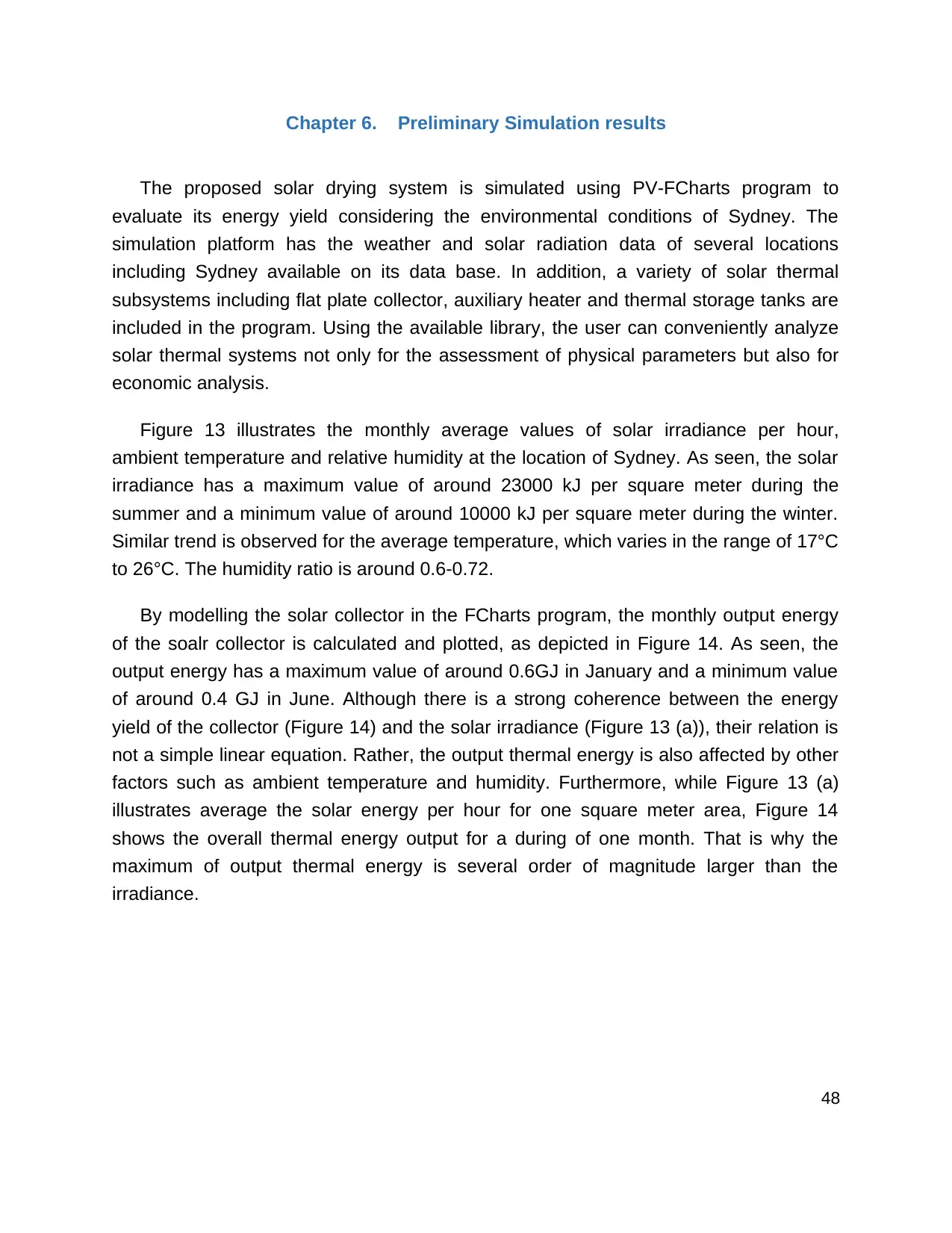
Chapter 6. Preliminary Simulation results
The proposed solar drying system is simulated using PV-FCharts program to
evaluate its energy yield considering the environmental conditions of Sydney. The
simulation platform has the weather and solar radiation data of several locations
including Sydney available on its data base. In addition, a variety of solar thermal
subsystems including flat plate collector, auxiliary heater and thermal storage tanks are
included in the program. Using the available library, the user can conveniently analyze
solar thermal systems not only for the assessment of physical parameters but also for
economic analysis.
Figure 13 illustrates the monthly average values of solar irradiance per hour,
ambient temperature and relative humidity at the location of Sydney. As seen, the solar
irradiance has a maximum value of around 23000 kJ per square meter during the
summer and a minimum value of around 10000 kJ per square meter during the winter.
Similar trend is observed for the average temperature, which varies in the range of 17°C
to 26°C. The humidity ratio is around 0.6-0.72.
By modelling the solar collector in the FCharts program, the monthly output energy
of the soalr collector is calculated and plotted, as depicted in Figure 14. As seen, the
output energy has a maximum value of around 0.6GJ in January and a minimum value
of around 0.4 GJ in June. Although there is a strong coherence between the energy
yield of the collector (Figure 14) and the solar irradiance (Figure 13 (a)), their relation is
not a simple linear equation. Rather, the output thermal energy is also affected by other
factors such as ambient temperature and humidity. Furthermore, while Figure 13 (a)
illustrates average the solar energy per hour for one square meter area, Figure 14
shows the overall thermal energy output for a during of one month. That is why the
maximum of output thermal energy is several order of magnitude larger than the
irradiance.
48
(a) (b)
(c)
Figure 13. Monthly average value of a) solar irradiance, b) ambient
temperature, c) humidity ratio
49
(c)
Figure 13. Monthly average value of a) solar irradiance, b) ambient
temperature, c) humidity ratio
49
Paraphrase This Document
Need a fresh take? Get an instant paraphrase of this document with our AI Paraphraser
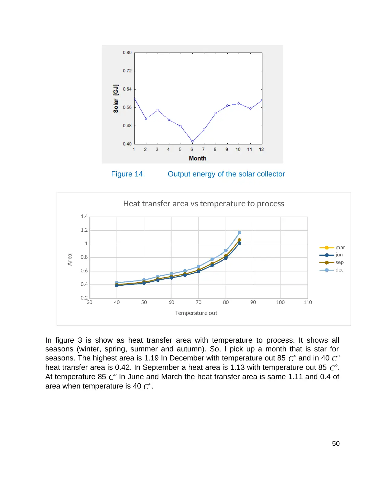
Figure 14. Output energy of the solar collector
30 40 50 60 70 80 90 100 110
0.2
0.4
0.6
0.8
1
1.2
1.4
Heat transfer area vs temperature to process
mar
jun
sep
dec
Temperature out
Area
In figure 3 is show as heat transfer area with temperature to process. It shows all
seasons (winter, spring, summer and autumn). So, I pick up a month that is star for
seasons. The highest area is 1.19 In December with temperature out 85 Co and in 40 Co
heat transfer area is 0.42. In September a heat area is 1.13 with temperature out 85 Co.
At temperature 85 Co In June and March the heat transfer area is same 1.11 and 0.4 of
area when temperature is 40 Co.
50
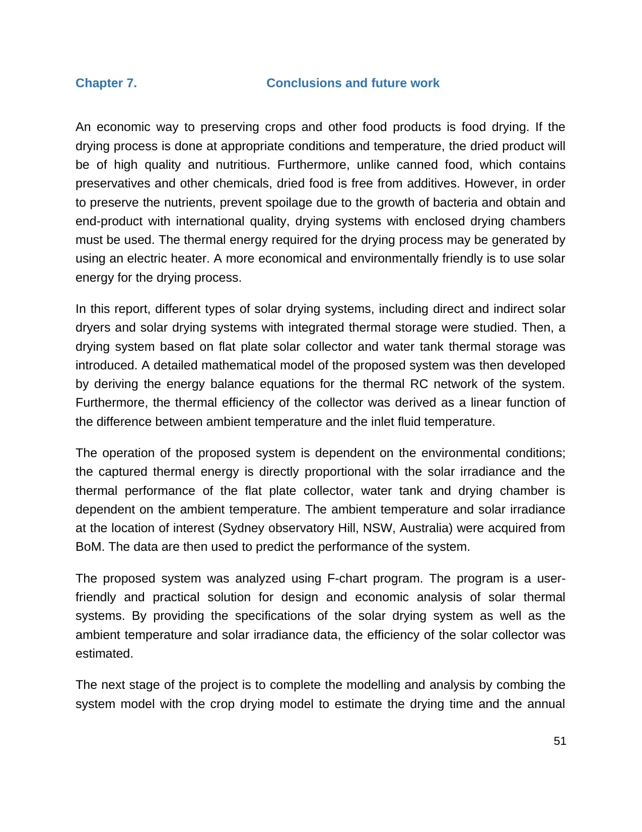
Chapter 7. Conclusions and future work
An economic way to preserving crops and other food products is food drying. If the
drying process is done at appropriate conditions and temperature, the dried product will
be of high quality and nutritious. Furthermore, unlike canned food, which contains
preservatives and other chemicals, dried food is free from additives. However, in order
to preserve the nutrients, prevent spoilage due to the growth of bacteria and obtain and
end-product with international quality, drying systems with enclosed drying chambers
must be used. The thermal energy required for the drying process may be generated by
using an electric heater. A more economical and environmentally friendly is to use solar
energy for the drying process.
In this report, different types of solar drying systems, including direct and indirect solar
dryers and solar drying systems with integrated thermal storage were studied. Then, a
drying system based on flat plate solar collector and water tank thermal storage was
introduced. A detailed mathematical model of the proposed system was then developed
by deriving the energy balance equations for the thermal RC network of the system.
Furthermore, the thermal efficiency of the collector was derived as a linear function of
the difference between ambient temperature and the inlet fluid temperature.
The operation of the proposed system is dependent on the environmental conditions;
the captured thermal energy is directly proportional with the solar irradiance and the
thermal performance of the flat plate collector, water tank and drying chamber is
dependent on the ambient temperature. The ambient temperature and solar irradiance
at the location of interest (Sydney observatory Hill, NSW, Australia) were acquired from
BoM. The data are then used to predict the performance of the system.
The proposed system was analyzed using F-chart program. The program is a user-
friendly and practical solution for design and economic analysis of solar thermal
systems. By providing the specifications of the solar drying system as well as the
ambient temperature and solar irradiance data, the efficiency of the solar collector was
estimated.
The next stage of the project is to complete the modelling and analysis by combing the
system model with the crop drying model to estimate the drying time and the annual
51
capacity of the dryer. Furthermore, economic analysis will be conducted to evaluate the
cost of the system and the return on investment.
In order to prevent spoilage and enhance the quality, modern food drying schemes
place the product within an enclosed space. This way, the product is preserved against
insects and animals. By controlling the temperature of the enclosure and application of
heat, the drying process is fastened, and the growing of bacteria is prevented.
Therefore, a high-quality product is produced. One way to produce the heat required for
the drying process is using a fuel-based or electrical heater. Alternatively, the heat can
be obtained from the sun’s energy. While the former technique provides more flexibility
in terms of temperature control, the later method is more economical and
environmentally friendly. The reason is that fuel-based and electrical dryers consume
large amounts of fuel and electrical energy over the drying time span. Apart from the
additional cost, both techniques contribute to large amounts of carbon emission.
a heat transfer exchanger is a way to produce temperature out for drying food factory. It
produces temperature by using solar system to have temperature in from a sun. A level
of temperature out that produce from heat exchanger it depends on area of exchanger.
If area is big then a temperature will be high but if is a small area of a temperature will
be low. The purpose of these experiments was to investigate an area of heat exchanger
and a temperature out. Our result that we got is a temperature out for a seasons and
area to decided which temperature that can be used. In the last a result that chose for
months that will start of seasons to have highest temperature and lowest with area that
should be used. In future, a solar system with heat exchanger will be common not just
factory will be in houses and villages. So, it will help human to drying food fast, cheap
without using electricity there will be saving money and its clean no bacteria or germs.
Also, you can save it from animals and insects.
52
Secure Best Marks with AI Grader
Need help grading? Try our AI Grader for instant feedback on your assignments.
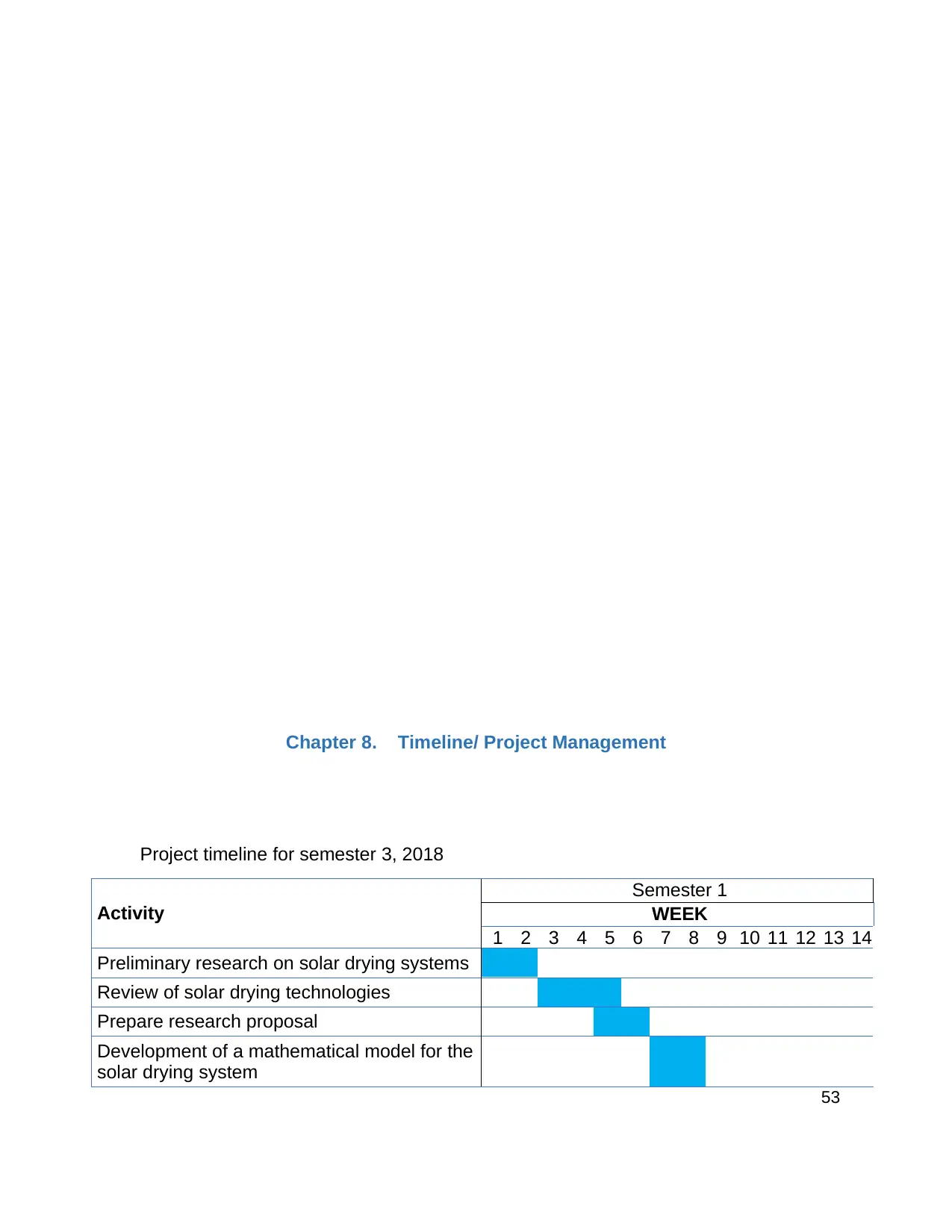
Chapter 8. Timeline/ Project Management
Project timeline for semester 3, 2018
Activity
Semester 1
WEEK
1 2 3 4 5 6 7 8 9 10 11 12 13 14
Preliminary research on solar drying systems
Review of solar drying technologies
Prepare research proposal
Development of a mathematical model for the
solar drying system
53
Project timeline for semester 3, 2018
Activity
Semester 1
WEEK
1 2 3 4 5 6 7 8 9 10 11 12 13 14
Preliminary research on solar drying systems
Review of solar drying technologies
Prepare research proposal
Development of a mathematical model for the
solar drying system
53

Data collection
Identify the mechanical and thermal
specifications of the system under study
Energy efficiency studies using F-chart
program
Compose progress report
Project timeline for semester 2, 2019
Activity
Semester 2
Week
1 2 3 4 5 6 7 8 9 1
0 11 12 13 14 15
Mathematical modelling and analysis of the drying
process
Analysis of the system’s performance based on F-
chart results
Calculate heat exchanger area
Comparing area with temperature out of heat
exchanger
Financial analysis of the system
Compose Final report
54
Bibliography
Al-Juamily, K.E., Khalifa, A.J.N. and Yassen, T.A., 2007. Testing of the performance of
a fruit and vegetable solar drying system in Iraq. Desalination, 209(1-3), pp.163-
170.
BANIASADI, E., RANJBAR, S. & BOOSTANIPOUR, O. 2017. Experimental
investigation of the performance of a mixed-mode solar dryer with thermal energy
storage. Renewable energy, 112, 143-150.
CHAUHAN, P. S., KUMAR, A. & TEKASAKUL, P. 2015. Applications of software in
solar drying systems: a review. Renewable and Sustainable Energy Reviews, 51,
1326-1337.
BANIASADI, E., et al. (2017). "Experimental investigation of the performance of a
mixed-mode solar dryer with thermal energy storage." Renewable energy 112: 143-150.
DUFFIE, J. A. & BECKMAN, W. A. 2013. Solar engineering of thermal processes, John
Wiley & Sons.
HAMDI, I., KOOLI, S., ELKHADRAOUI, A., AZAIZIA, Z., ABDELHAMID, F. & GUIZANI,
A. 2018. Experimental study and numerical modeling for drying grapes under
solar greenhouse. Renewable Energy, 127, 936-946.
Fudholi, A., Sopian, K., Yazdi, M.H., Ruslan, M.H., Gabbasa, M. and Kazem, H.A.,
2014. Performance analysis of solar drying system for red chili. Solar Energy, 99,
pp.47-54.
Fudholi, A., Sopian, K., Othman, M.Y. and Ruslan, M.H., 2014. Energy and exergy
analyses of solar drying system of red seaweed. Energy and Buildings, 68, pp.121-129.
Fudholi, A., Sopian, K., Bakhtyar, B., Gabbasa, M., Othman, M.Y. and Ruslan, M.H.,
2015. Review of solar drying systems with air based solar collectors in
Malaysia. Renewable and Sustainable Energy Reviews, 51, pp.1191-1204.
HAO, W., LU, Y., LAI, Y., YU, H. & LYU, M. 2018. Research on operation strategy and
performance prediction of flat plate solar collector with dual-function for drying
agricultural products. Renewable Energy, 127, 685-696.
Janjai, S., Srisittipokakun, N. and Bala, B.K., 2008. Experimental and modelling
performances of a roof-integrated solar drying system for drying herbs and
spices. Energy, 33(1), pp.91-103.
JAIN, D. & TEWARI, P. 2015. Performance of indirect through pass natural convective
solar crop dryer with phase change thermal energy storage. Renewable energy,
80, 244-250.
Karim, M.A. and Hawlader, M., 2004. Development of solar air collectors for drying
applications. Energy conversion and management, 45(3), pp.329-344.
55
Paraphrase This Document
Need a fresh take? Get an instant paraphrase of this document with our AI Paraphraser
Li, H., Yu, Y., Niu, F., Shafik, M. and Chen, B., 2014. Performance of a coupled cooling
system with earth-to-air heat exchanger and solar chimney. Renewable
Energy, 62, pp.468-477.
Lunde, P.J., 1980. Solar thermal engineering: space heating and hot water
systems. New York, John Wiley and Sons, Inc., 1980. 635 p.
METEOROLOGY, B. O. 2019a. 1-minute solar irradiation recordings for 2018 [Online].
Available: http://www.bom.gov.au/ [Accessed].
METEOROLOGY, B. O. 2019b. Weather recordings for 2018 [Online]. Available:
http://www.bom.gov.au/ [Accessed].
Midilli, A., 2001. Determination of pistachio drying behaviour and conditions in a solar
drying system. International Journal of Energy Research, 25(8), pp.715-725.
Maerefat, M. and Haghighi, A.P., 2010. Passive cooling of buildings by using integrated
earth to air heat exchanger and solar chimney. Renewable Energy, 35(10),
pp.2316-2324.
Mustayen, a., mekhilef, s. & saidur, r. 2014. Performance study of different solar dryers:
A review. Renewable and Sustainable Energy Reviews, 34, 463-470.
Othman, M.Y.H., Sopian, K., Yatim, B. and Daud, W.R.W., 2006. Development of
advanced solar assisted drying systems. Renewable Energy, 31(5), pp.703-709.
Smitabhindu, R., Janjai, S. and Chankong, V., 2008. Optimization of a solar-assisted
drying system for drying bananas. Renewable Energy, 33(7), pp.1523-1531.
Selvaraj, m., sadagopan, p., balakrishnan, n. & bhuvaneswaran, m. 2018. a review of
solar energy collection technology to heat air as thermal, using flat plate collector
and integrated with drying chamber for drying food products. Indian Journal of
Scientific Research, 281-287.
Shah, R.K. and Sekulic, D.P., 2003. Fundamentals of heat exchanger design. John
Wiley & Sons.
Sopian, K., Liu, H.T., Kakac, S. and Veziroglu, T.N., 2000. Performance of a double
pass photovoltaic thermal solar collector suitable for solar drying
systems. Energy Conversion and Management, 41(4), pp.353-365.
tomar, v., tiwari, g. & norton, b. 2017. Solar dryers for tropical food preservation:
Thermophysics of crops, systems and components. Solar Energy, 154, 2-13.
Vagenas, g., drouzas, a., marinos-kouris, d. & saravacos, G. 1990. Predictive equations
for thermophysical properties of plant foods. Engineering and food, 1, 399.
Vaivudh, S., Rakwichian, W. and Chindaruksa, S., 2008. Heat transfer of high thermal
energy storage with heat exchanger for solar trough power plant. Energy
conversion and management, 49(11), pp.3311-3317.
56
1 out of 56
Your All-in-One AI-Powered Toolkit for Academic Success.
+13062052269
info@desklib.com
Available 24*7 on WhatsApp / Email
![[object Object]](/_next/static/media/star-bottom.7253800d.svg)
Unlock your academic potential
© 2024 | Zucol Services PVT LTD | All rights reserved.