Fracture Mechanics 1

Verified

Added on  2023/04/21

|9
|1662
|137
AI Summary
This document provides study material and solved assignments for Fracture Mechanics. It covers topics such as composite modulus calculation, yield behavior in tension and compression, stress calculation, and methods for predicting yield. The document also includes a case study on the toughness of a steel composite and the safety assessment of a pressure vessel.

Contribute Materials

Your contribution can guide someone’s learning journey. Share your documents today.
Document Page
Fracture Mechanics 1
FRACTURE MECHANICS
By
(Name)
(Course)
(Professor’s Name)
(Institution)
(State)
(Date)

Secure Best Marks with AI Grader

Need help grading? Try our AI Grader for instant feedback on your assignments.
Document Page
Fracture Mechanics 2
Question 3 (Block 1 Learning Outcomes 2.3, 2.6, 4.2, 7.3)
This question carries 30% of the marks for this assignment
A composite is produced from titanium reinforced with aligned silicon carbide fibres. The
elastic modulus of titanium is 118 GPa and silicon carbide 380 GPa. The composite contains
approximately 60% titanium and 40% fibres.
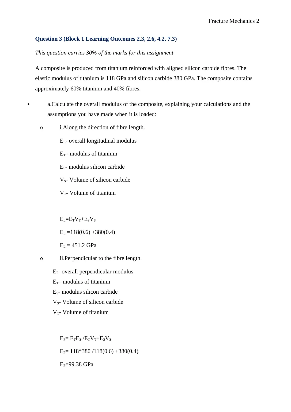
a.Calculate the overall modulus of the composite, explaining your calculations and the
assumptions you have made when it is loaded:
o i.Along the direction of fibre length.
EL- overall longitudinal modulus
ET - modulus of titanium
ES- modulus silicon carbide
VS- Volume of silicon carbide
VT- Volume of titanium
EL=ETVT+ESVS
EL =118(0.6) +380(0.4)
EL = 451.2 GPa
o ii.Perpendicular to the fibre length.
EP- overall perpendicular modulus
ET - modulus of titanium
ES- modulus silicon carbide
VS- Volume of silicon carbide
VT- Volume of titanium
EP= ETES /ETVT+ESVS
EP= 118*380 /118(0.6) +380(0.4)
EP=99.38 GPa
Document Page
Fracture Mechanics 3
(8 marks)
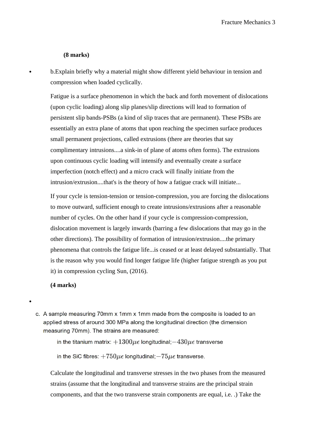
b.Explain briefly why a material might show different yield behaviour in tension and
compression when loaded cyclically.
Fatigue is a surface phenomenon in which the back and forth movement of dislocations
(upon cyclic loading) along slip planes/slip directions will lead to formation of
persistent slip bands-PSBs (a kind of slip traces that are permanent). These PSBs are
essentially an extra plane of atoms that upon reaching the specimen surface produces
small permanent projections, called extrusions (there are theories that say
complimentary intrusions....a sink-in of plane of atoms often forms). The extrusions
upon continuous cyclic loading will intensify and eventually create a surface
imperfection (notch effect) and a micro crack will finally initiate from the
intrusion/extrusion....that's is the theory of how a fatigue crack will initiate...
If your cycle is tension-tension or tension-compression, you are forcing the dislocations
to move outward, sufficient enough to create intrusions/extrusions after a reasonable
number of cycles. On the other hand if your cycle is compression-compression,
dislocation movement is largely inwards (barring a few dislocations that may go in the
other directions). The possibility of formation of intrusion/extrusion....the primary
phenomena that controls the fatigue life...is ceased or at least delayed substantially. That
is the reason why you would find longer fatigue life (higher fatigue strength as you put
it) in compression cycling Sun, (2016).
(4 marks)

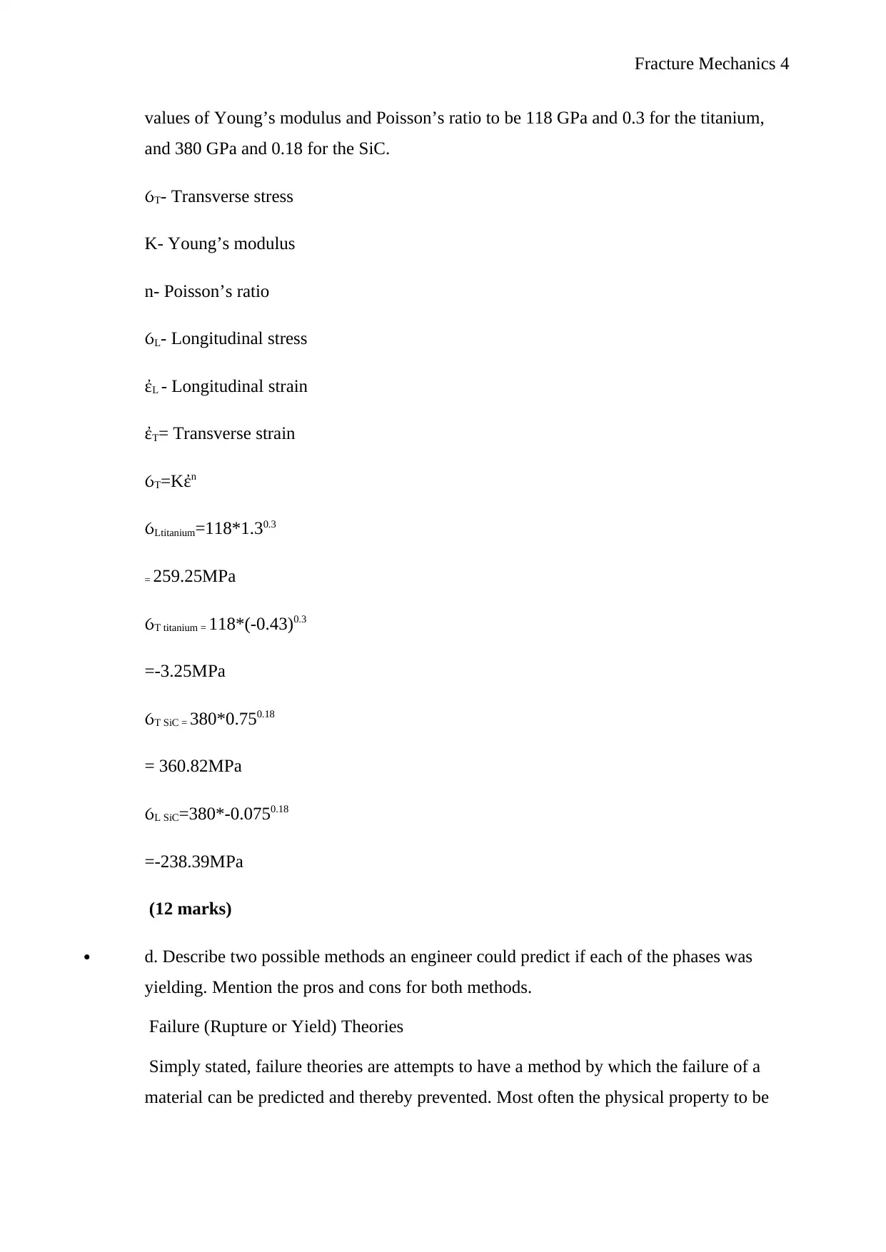
Calculate the longitudinal and transverse stresses in the two phases from the measured
strains (assume that the longitudinal and transverse strains are the principal strain
components, and that the two transverse strain components are equal, i.e. .) Take the
Document Page
Fracture Mechanics 4
values of Young’s modulus and Poisson’s ratio to be 118 GPa and 0.3 for the titanium,
and 380 GPa and 0.18 for the SiC.
T- Transverse stress
K- Young’s modulus
n- Poisson’s ratio
L- Longitudinal stress
L - Longitudinal strain
T= Transverse strain
T=Kἐn
Ltitanium=118*1.30.3
= 259.25MPa
T titanium = 118*(-0.43)0.3
=-3.25MPa
T SiC = 380*0.750.18
= 360.82MPa
L SiC=380*-0.0750.18
=-238.39MPa
(12 marks)
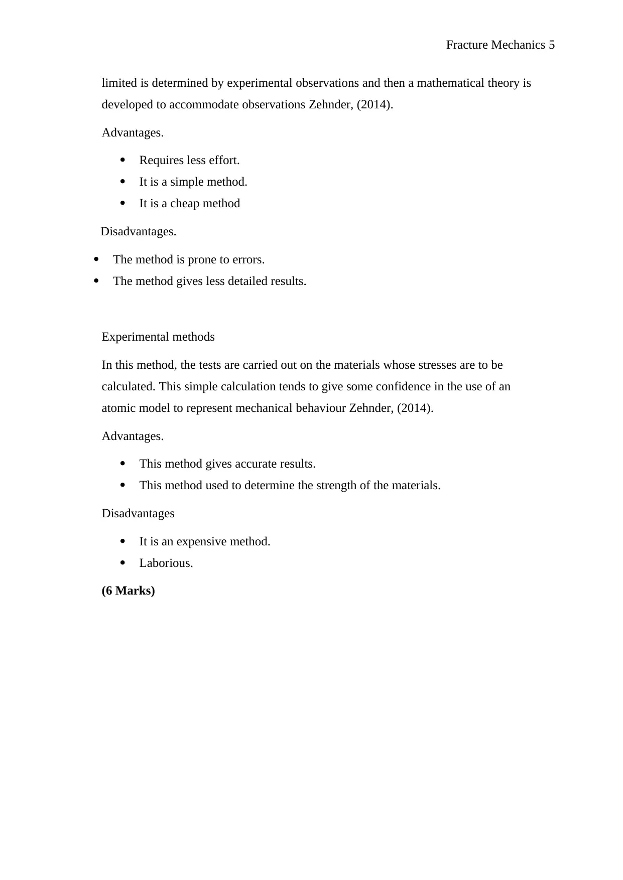
d. Describe two possible methods an engineer could predict if each of the phases was
yielding. Mention the pros and cons for both methods.
Failure (Rupture or Yield) Theories
Simply stated, failure theories are attempts to have a method by which the failure of a
material can be predicted and thereby prevented. Most often the physical property to be

Secure Best Marks with AI Grader

Need help grading? Try our AI Grader for instant feedback on your assignments.
Document Page
Fracture Mechanics 5
limited is determined by experimental observations and then a mathematical theory is
developed to accommodate observations Zehnder, (2014).
Advantages.
Requires less effort.
It is a simple method.
It is a cheap method
Disadvantages.
The method is prone to errors.
The method gives less detailed results.
Experimental methods
In this method, the tests are carried out on the materials whose stresses are to be
calculated. This simple calculation tends to give some confidence in the use of an
atomic model to represent mechanical behaviour Zehnder, (2014).
Advantages.
This method gives accurate results.
This method used to determine the strength of the materials.
Disadvantages
It is an expensive method.
Laborious.
(6 Marks)
Document Page
Fracture Mechanics 6
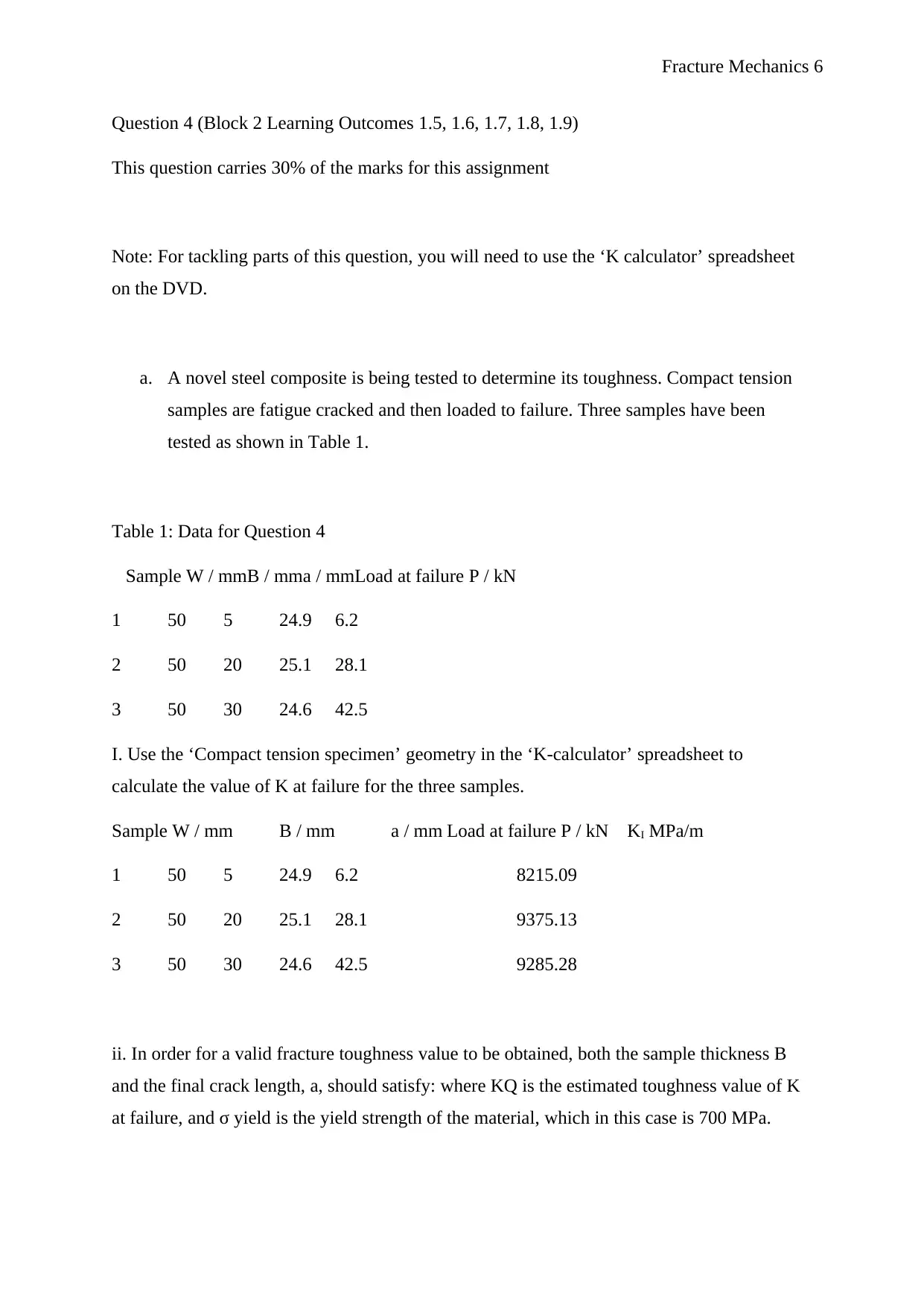
Question 4 (Block 2 Learning Outcomes 1.5, 1.6, 1.7, 1.8, 1.9)
This question carries 30% of the marks for this assignment
Note: For tackling parts of this question, you will need to use the ‘K calculator’ spreadsheet
on the DVD.
a. A novel steel composite is being tested to determine its toughness. Compact tension
samples are fatigue cracked and then loaded to failure. Three samples have been
tested as shown in Table 1.
Table 1: Data for Question 4
Sample W / mmB / mma / mmLoad at failure P / kN
1 50 5 24.9 6.2
2 50 20 25.1 28.1
3 50 30 24.6 42.5
I. Use the ‘Compact tension specimen’ geometry in the ‘K-calculator’ spreadsheet to
calculate the value of K at failure for the three samples.
Sample W / mm B / mm a / mm Load at failure P / kN KI MPa/m
1 50 5 24.9 6.2 8215.09
2 50 20 25.1 28.1 9375.13
3 50 30 24.6 42.5 9285.28
ii. In order for a valid fracture toughness value to be obtained, both the sample thickness B
and the final crack length, a, should satisfy: where KQ is the estimated toughness value of K
at failure, and σ yield is the yield strength of the material, which in this case is 700 MPa.
Document Page
Fracture Mechanics 7
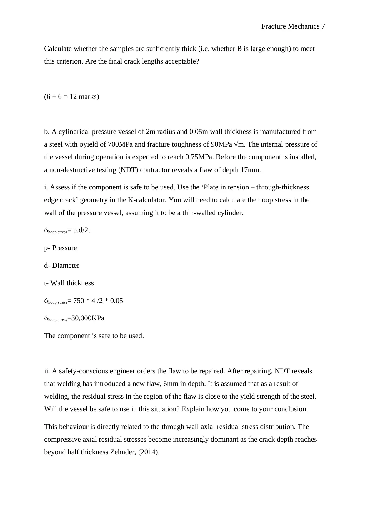
Calculate whether the samples are sufficiently thick (i.e. whether B is large enough) to meet
this criterion. Are the final crack lengths acceptable?
(6 + 6 = 12 marks)
b. A cylindrical pressure vessel of 2m radius and 0.05m wall thickness is manufactured from
a steel with σyield of 700MPa and fracture toughness of 90MPa √m. The internal pressure of
the vessel during operation is expected to reach 0.75MPa. Before the component is installed,
a non-destructive testing (NDT) contractor reveals a flaw of depth 17mm.
i. Assess if the component is safe to be used. Use the ‘Plate in tension – through-thickness
edge crack’ geometry in the K-calculator. You will need to calculate the hoop stress in the
wall of the pressure vessel, assuming it to be a thin-walled cylinder.
hoop stress= p.d/2t
p- Pressure
d- Diameter
t- Wall thickness
hoop stress= 750 * 4 /2 * 0.05
hoop stress=30,000KPa
The component is safe to be used.
ii. A safety-conscious engineer orders the flaw to be repaired. After repairing, NDT reveals
that welding has introduced a new flaw, 6mm in depth. It is assumed that as a result of
welding, the residual stress in the region of the flaw is close to the yield strength of the steel.
Will the vessel be safe to use in this situation? Explain how you come to your conclusion.
This behaviour is directly related to the through wall axial residual stress distribution. The
compressive axial residual stresses become increasingly dominant as the crack depth reaches
beyond half thickness Zehnder, (2014).

Paraphrase This Document

Need a fresh take? Get an instant paraphrase of this document with our AI Paraphraser
Document Page
Fracture Mechanics 8
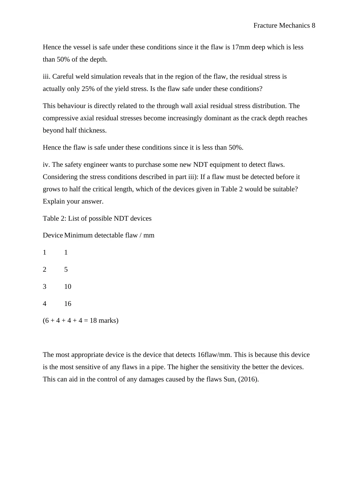
Hence the vessel is safe under these conditions since it the flaw is 17mm deep which is less
than 50% of the depth.
iii. Careful weld simulation reveals that in the region of the flaw, the residual stress is
actually only 25% of the yield stress. Is the flaw safe under these conditions?
This behaviour is directly related to the through wall axial residual stress distribution. The
compressive axial residual stresses become increasingly dominant as the crack depth reaches
beyond half thickness.
Hence the flaw is safe under these conditions since it is less than 50%.
iv. The safety engineer wants to purchase some new NDT equipment to detect flaws.
Considering the stress conditions described in part iii): If a flaw must be detected before it
grows to half the critical length, which of the devices given in Table 2 would be suitable?
Explain your answer.
Table 2: List of possible NDT devices
Device Minimum detectable flaw / mm
1 1
2 5
3 10
4 16
(6 + 4 + 4 + 4 = 18 marks)
The most appropriate device is the device that detects 16flaw/mm. This is because this device
is the most sensitive of any flaws in a pipe. The higher the sensitivity the better the devices.
This can aid in the control of any damages caused by the flaws Sun, (2016).
Document Page
Fracture Mechanics 9
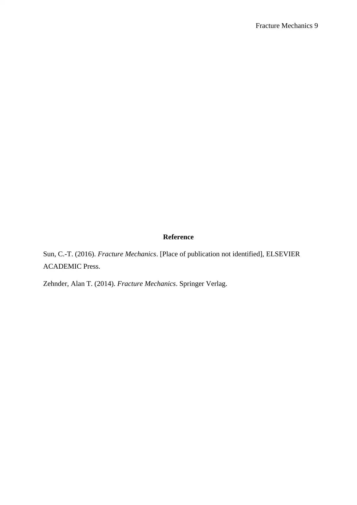
Reference
Sun, C.-T. (2016). Fracture Mechanics. [Place of publication not identified], ELSEVIER
ACADEMIC Press.
Zehnder, Alan T. (2014). Fracture Mechanics. Springer Verlag.
1 out of 9
circle_padding
hide_on_mobile
zoom_out_icon
[object Object]

Your All-in-One AI-Powered Toolkit for Academic Success.

Available 24*7 on WhatsApp / Email

[object Object]