Full Duplex Technology for Self-Interference Cancellation in Vehicular Networks
VerifiedAdded on 2023/06/09
|11
|2660
|104
AI Summary
This paper discusses the use of full duplex technology for self-interference cancellation in vehicular networks. It proposes a protocol to solve the hidden node problem using the CSMA/CA protocol. The paper also includes an implementation algorithm and protocol, MATLAB simulation, and methods to improve throughput and decrease packet error rate in RSU.
Contribute Materials
Your contribution can guide someone’s learning journey. Share your
documents today.
Telecommunication Project
Student Name
PhD. Level assignment
Institutional Affiliation
Date of submission
1
Student Name
PhD. Level assignment
Institutional Affiliation
Date of submission
1
Secure Best Marks with AI Grader
Need help grading? Try our AI Grader for instant feedback on your assignments.
Introduction
Full duplex technology ensures that the Roadside Unit, RSU, is able to transmit and
receive signals from the Vehicle user equipment within and without the network A region.
Unfortunately, the RSU experiences the self-interference as it can hear the transmit and receive
signals in itself [1]. The self-interference is generated when the two signals, transmit and receive,
combine to form a stronger signal [2]. The full duplex technology improves the quality of service
in that when the VUE1 is unable to use the dedicated channel to transmit the signals, it can send
the signals to the RSU which forwards them using a dedicated downlink channel to the receiver
before the message expires or experiences packet loss and errors [3]. It is important to highlight
that the Roadside unit performs the self-interference calculation in digital form. Initially, the
digital cancellation technique was found to eliminate all the transmitter impairments and
mitigates the receivers phase noise and non-linearity effects [4]. The full duplex allows a
communication system to transmit and receive messages on a given frequency slot. It optimizes
the use of the communication systems frequency spectrum.
Mobile communication systems have transmission ranges and not all stations are found
within the radio range of each other. The Carrier Sense Multiple Access, CSMA, may not work
in such a system. The hidden node problem is such that other sender’s information are hidden
from the current sender, so that transmission at the same receiver tend to cause collisions [5].
The use of a Medium Access Control Protocol such as the slotted Aloha, synchronous and
asynchronous protocols, adaptive scheme, and cooperative sensing are used [6]. This paper seeks
to use the CSMA/CA protocol to solve the hidden node problem in either the asynchronous or
synchronous mode. Implementing the MAC design control is set to improve the fairness of
network from 0.85 to 0.98. It increases the throughput of the downlink and uplink by reducing
the collision in the full duplex modes.
Problem statement
In the scenario, the VUE1 is unable to join NET.A. the VUE1 wishes to send an urgent message
to a vehicle system in the network. The VUE1 is unable to wait long enough to find a
transmission opportunity. It, therefore, decides to send the message to RSU, which operates on
full duplex mode, with dedicated downlink channels to the network A region.
2
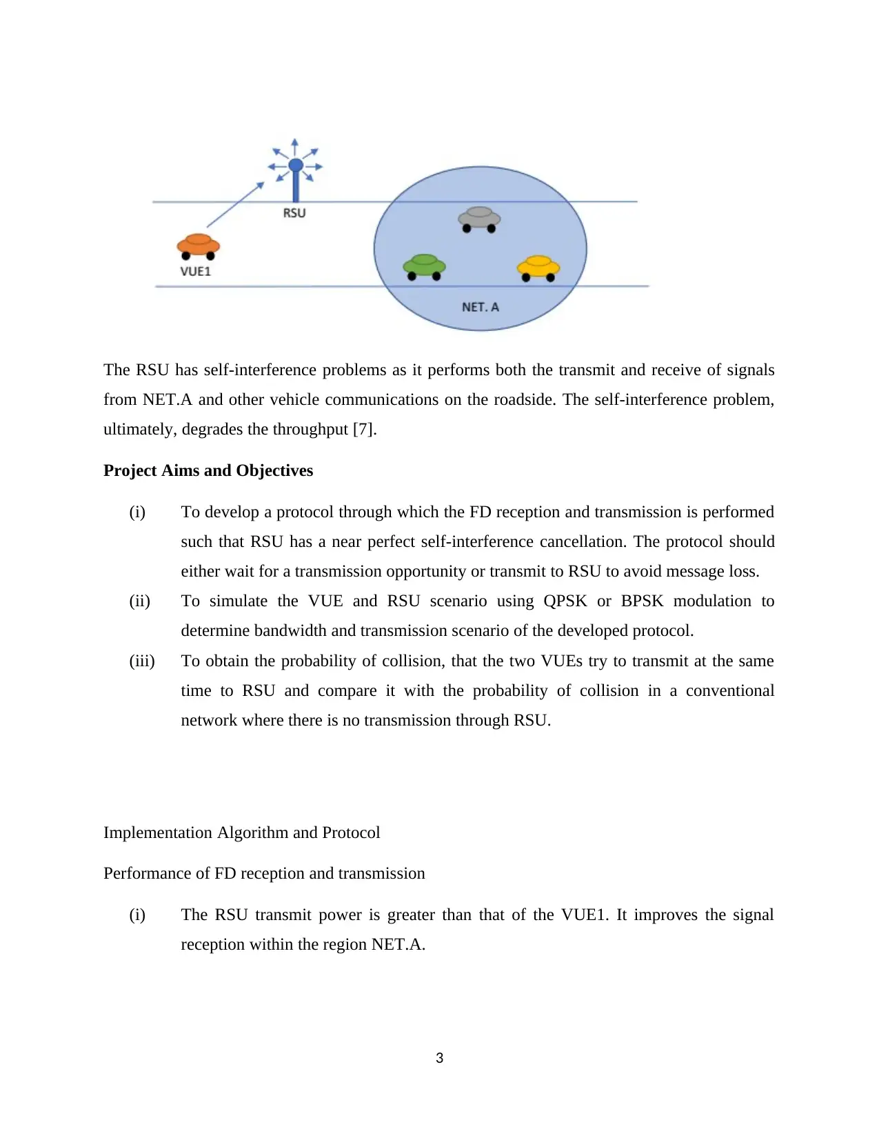
The RSU has self-interference problems as it performs both the transmit and receive of signals
from NET.A and other vehicle communications on the roadside. The self-interference problem,
ultimately, degrades the throughput [7].
Project Aims and Objectives
(i) To develop a protocol through which the FD reception and transmission is performed
such that RSU has a near perfect self-interference cancellation. The protocol should
either wait for a transmission opportunity or transmit to RSU to avoid message loss.
(ii) To simulate the VUE and RSU scenario using QPSK or BPSK modulation to
determine bandwidth and transmission scenario of the developed protocol.
(iii) To obtain the probability of collision, that the two VUEs try to transmit at the same
time to RSU and compare it with the probability of collision in a conventional
network where there is no transmission through RSU.
Implementation Algorithm and Protocol
Performance of FD reception and transmission
(i) The RSU transmit power is greater than that of the VUE1. It improves the signal
reception within the region NET.A.
3
(ii) The normal or emergency message sent by the VUE1 has a timeout that will be
broadcasted to the surrounding vehicles within Tout. Any message that passes the
Tout is deemed to have expired and no longer useful [8].
(iii) In this algorithm or protocol, the VUE1 must wait for the Tout to find a transmission
opportunity. When none is available, it switches to transmitting to RSU to avoid the
message loss.
0< β <1−self interference cancellation( suppression) parameter
β=0 ;no residual self interference
β=1 ;no cancellation
r3 −transmitter power of roadside unit
The amount of self-interference is given as,
S Iamount=β∗r3
r1=signal ¿ noise ratio received ¿ other nodes
r2= power transmitted ¿ B
There is an input-output relation of the ADC which is given as,
y ADC ( n )=α √gAGC y ( n ) +ωAGC ( n )
It gives the clipping plus quantization noise when uncorrelated with the input and the attenuation
factor. The attenuation or degrading of throughput is expressed as,
α = √ gAGC ( E { y ( n )∗y ADC ( n ) }
E {| y ( n ) 2
|} )
The transmit power is given as,
r3 =E {|y ADC ( n )|2
}−α2 g ADC E {| y ( n )|2
}
The received power is expressed as,
r2=r3− (−174 +10 log10 Bw+ Pn f receiver
+ Pcc )
4
Secure Best Marks with AI Grader
Need help grading? Try our AI Grader for instant feedback on your assignments.
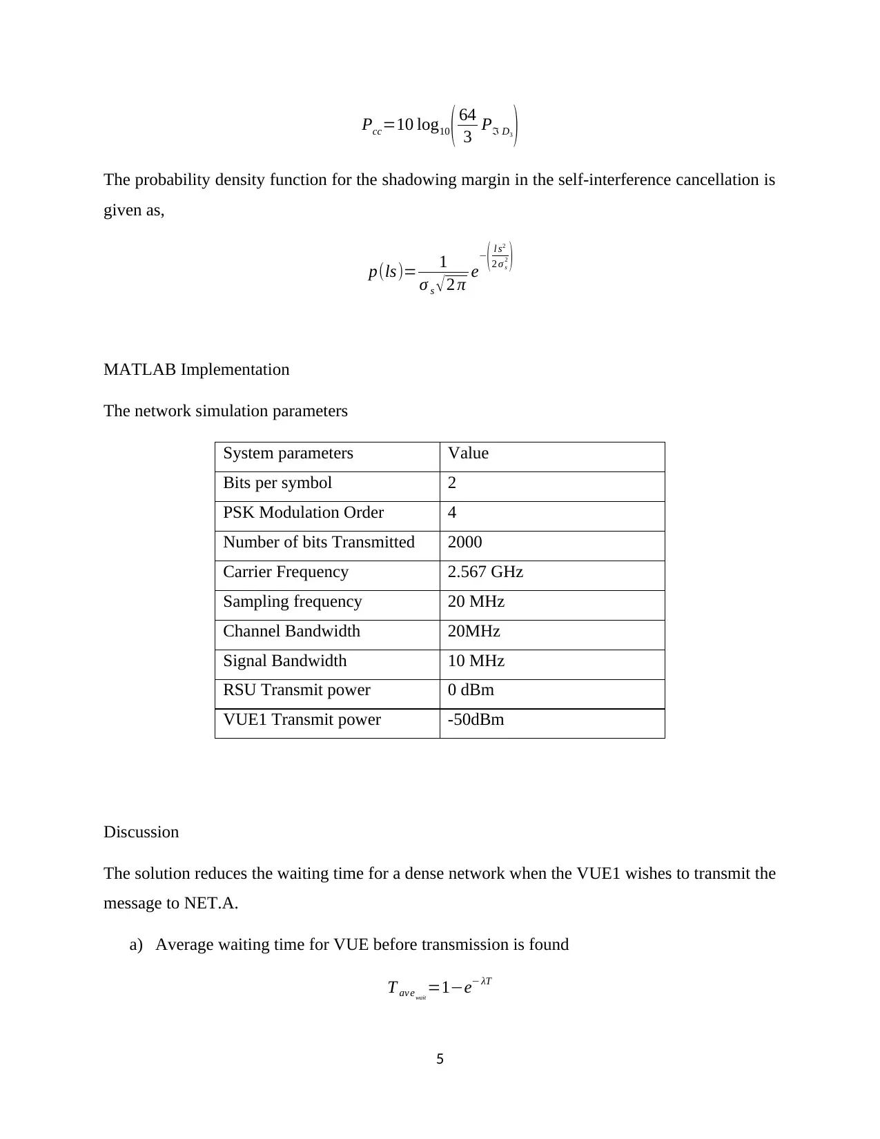
Pcc=10 log10 ( 64
3 Pℑ D3 )
The probability density function for the shadowing margin in the self-interference cancellation is
given as,
p(ls)= 1
σ s √2 π e
−
( l s2
2 σ s
2 )
MATLAB Implementation
The network simulation parameters
System parameters Value
Bits per symbol 2
PSK Modulation Order 4
Number of bits Transmitted 2000
Carrier Frequency 2.567 GHz
Sampling frequency 20 MHz
Channel Bandwidth 20MHz
Signal Bandwidth 10 MHz
RSU Transmit power 0 dBm
VUE1 Transmit power -50dBm
Discussion
The solution reduces the waiting time for a dense network when the VUE1 wishes to transmit the
message to NET.A.
a) Average waiting time for VUE before transmission is found
T av ewait
=1−e− λT
5
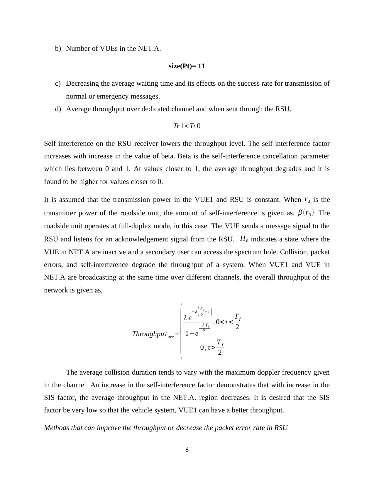
b) Number of VUEs in the NET.A.
size(Pt)= 11
c) Decreasing the average waiting time and its effects on the success rate for transmission of
normal or emergency messages.
d) Average throughput over dedicated channel and when sent through the RSU.
Tr 1< Tr 0
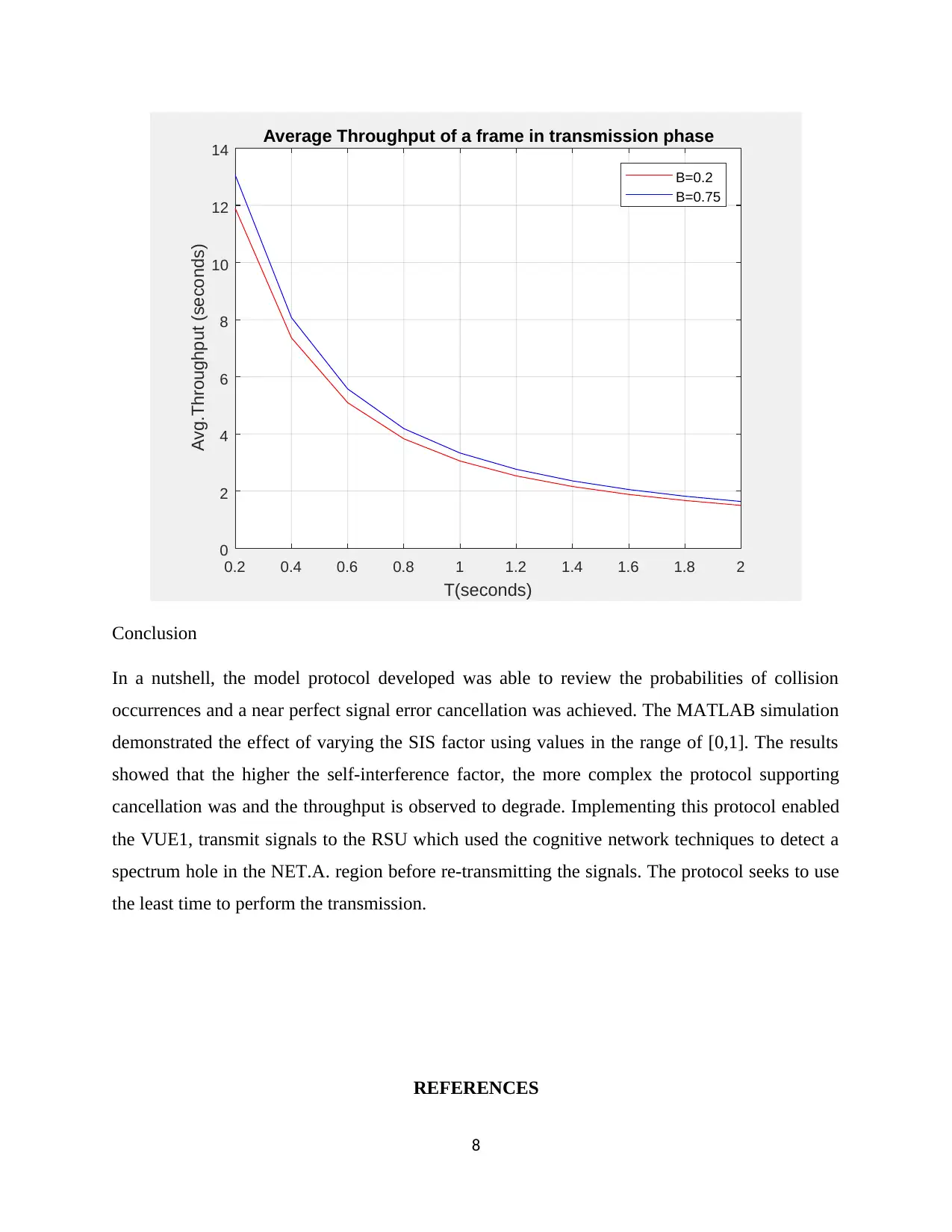
Self-interference on the RSU receiver lowers the throughput level. The self-interference factor
increases with increase in the value of beta. Beta is the self-interference cancellation parameter
which lies between 0 and 1. At values closer to 1, the average throughput degrades and it is
found to be higher for values closer to 0.
It is assumed that the transmission power in the VUE1 and RSU is constant. When r3 is the
transmitter power of the roadside unit, the amount of self-interference is given as, β (r3 ). The
roadside unit operates at full-duplex mode, in this case. The VUE sends a message signal to the
RSU and listens for an acknowledgement signal from the RSU. H0 indicates a state where the
VUE in NET.A are inactive and a secondary user can access the spectrum hole. Collision, packet
errors, and self-interference degrade the throughput of a system. When VUE1 and VUE in
NET.A are broadcasting at the same time over different channels, the overall throughput of the
network is given as,
Throughpu tave=
{ λ e−λ ( T f
2 −τ )
1−e
−λ Tf
2
, 0<τ < T f
2
0 , τ > T f
2
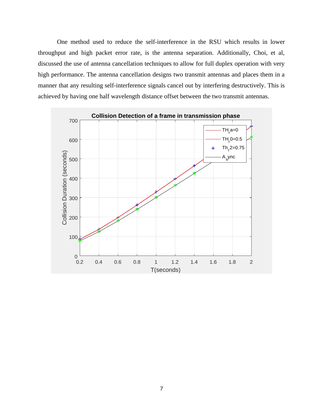
The average collision duration tends to vary with the maximum doppler frequency given
in the channel. An increase in the self-interference factor demonstrates that with increase in the
SIS factor, the average throughput in the NET.A. region decreases. It is desired that the SIS
factor be very low so that the vehicle system, VUE1 can have a better throughput.
Methods that can improve the throughput or decrease the packet error rate in RSU
6
One method used to reduce the self-interference in the RSU which results in lower
throughput and high packet error rate, is the antenna separation. Additionally, Choi, et al,
discussed the use of antenna cancellation techniques to allow for full duplex operation with very
high performance. The antenna cancellation designs two transmit antennas and places them in a
manner that any resulting self-interference signals cancel out by interfering destructively. This is
achieved by having one half wavelength distance offset between the two transmit antennas.
0.2 0.4 0.6 0.8 1 1.2 1.4 1.6 1.8 2
T(seconds)
0
100
200
300
400
500
600
700
Collision Duration (seconds)
Collision Detection of a frame in transmission phase
THra=0
THr0=0.5
Thr2=0.75
Async
7
Paraphrase This Document
Need a fresh take? Get an instant paraphrase of this document with our AI Paraphraser
0.2 0.4 0.6 0.8 1 1.2 1.4 1.6 1.8 2
T(seconds)
0
2
4
6
8
10
12
14
Avg.Throughput (seconds)
Average Throughput of a frame in transmission phase
B=0.2
B=0.75
Conclusion
In a nutshell, the model protocol developed was able to review the probabilities of collision
occurrences and a near perfect signal error cancellation was achieved. The MATLAB simulation
demonstrated the effect of varying the SIS factor using values in the range of [0,1]. The results
showed that the higher the self-interference factor, the more complex the protocol supporting
cancellation was and the throughput is observed to degrade. Implementing this protocol enabled
the VUE1, transmit signals to the RSU which used the cognitive network techniques to detect a
spectrum hole in the NET.A. region before re-transmitting the signals. The protocol seeks to use
the least time to perform the transmission.
REFERENCES
8
[1] J. I. Choi, M. Jain, K. Srinivasan, P. Levis and S. Katti, "Achieving single channel, full duplex
wireless communication," proceedings of the sixteenth annual international conference on Mobile
Compuing and Networking, vol. 10, pp. 1-12, 2010.
[2] W. Cheng and X. X. H. Zhang, "Full duplex wireless communications for cognitive radio networks,"
arXiv:1105.0034 [cs.IT], 2011.
[3] s. Sen, R. R. Choudhury and S. Nelakuditi, "Channel Estimation in OFDM Systems," Application
international conference on Mobile Computing and networking, Mobicom, pp. 25-36, 2010.
[4] W. Cheng, X. Zhang and H. Xhang, "Full duplex spectrum sensing and MAC protocol for
multichannel non-time slotted cognitive radio networks," IEEE Journal on Selected Areas in
Communications.
[5] M. Duarte and A. Sabharwal, "Full-duplex wireless communication using off-the-shelf radio,"
Feasibility and first results: In Forty-Fourth Asilomar Conference on Signals, systems, and
components, 2010.
[6] I. Gheorma and G. Gopalakrishnan, "RF Photonic techniques for same frequency simultaneous
duplex antenna operation," IEEE photonics Letters, vol. 19, no. 13, 2017.
[7] W. Zhang, R. Mallik and K. Letaief, "Optimization of cooperative spectrum sensing with energy
detection in cognitive radio networks," IEEE Transaction on wireless communication, vol. 8, no. 12,
pp. 5761-5766, 2009.
[8] S. W. Kim, Y. J. Chun and S. Kim, "Co-channel interference cancellation using single radio
frequence and baseband chain," Communications, IEEE Transactions, vol. 58, no. 7, pp. 169-2175,
2010.
[9] Y. Liang, Y. Zeng, E. Peh and A. Hoang, "Sensing Throughput tradeoff for cognitive radio network,"
IEEE Transaction on wireless communication , vol. 7, no. 4, 2008.
9
Appendix
%% simulating a full duplex system for VUE1 and RSU using BPSK modulation with
convolutional coding
clear
close all
clc
packet_size=1024; %bits
CR_frame_size=2; %packets
r_2=10; %transmit power decibels
r_3=3; %transmit power decibels
Ts=1e-3; %sensing slot size
inv_lambda=150e-3; %seconds
inv_mul=300; %seconds
fs=1e6; %sampling frequency(Hz)
a1=1/inv_mul;
a2=1/inv_lambda;
%% priori probabilities at the start of the VUE1 transmission
P_H0=a1/(a2+a1)
P_H1=a2/(a1+a2)
Ba=0.9;
Bb=0.5;
R0a=2*log(1+(r_2./(1+Ba)));
R0b=2*log(1+(r_2./(1+Bb)));
R1a=2*log(1+(r_2./(1+r_3+Ba)));
R1b=2*log(1+(r_2./(1+r_3+Bb)));
T=0:0.2:2;
%% collision detection and mitigation-using probabilities
T_wait=(1+(a2.*T)-(2*a2.*T+1).*exp(-a2.*T))./(2*a2.*T.*(1-exp(-a2.*T)));
Csma_dur=(a2.*T+exp(-a2.*T)-1)./(2*a2.*T.*(1-exp(-a2.*T)));
Pt=1-exp(-a2.*T);
R_T1=Pt.*((R0a.*(T_wait./T)+R1a.*(Csma_dur./T)));
R_T2=Pt.*((R0b.*(T_wait./T)+R1b.*(Csma_dur./T)));
figure(1)
plot(T,R_T1,'r')
xlabel('T(seconds)')
ylabel('Avg.Throughput (seconds)')
title('Average Throughput of a frame in transmission phase')
grid on
hold on
plot(T,R_T2,'b')
legend('B=0.2','B=0.75')
%% average VUE1 throughout for different values of the SIS factor, B
pf2a=0;
pf2b=1.5;
pf2c=2;
R_lbta=2.*P_H0.*(1-pf2a.*(2.*Ts./T)).*R_T1;
R_lbtb=2.*P_H0.*(1-pf2b.*(2.*Ts./T)).*R_T1;
10
Secure Best Marks with AI Grader
Need help grading? Try our AI Grader for instant feedback on your assignments.
R_lbtc=2.*P_H0.*(1-pf2c.*(2.*Ts./T)).*R_T1;
R_lbtd=2.*P_H0.*(1-pf2a.*(2.*Ts./T)).*R_T2;
R_lbte=2.*P_H0.*(1-pf2b.*(2.*Ts./T)).*R_T2;
R_lbtf=2.*P_H0.*(1-pf2c.*(2.*Ts./T)).*R_T2;
f1=R_lbta.^-1;
f2=R_lbtb.^-1;
f3=R_lbtc.^-1;
f4=R_lbtd.^-1;
f5=R_lbte.^-1;
f6=R_lbtf.^-1;
figure(2)
plot(T,f1,'r')
xlabel('T(seconds)')
ylabel('Collision Duration (seconds)')
title('Collision Detection of a frame in transmission phase')
grid on
hold on
plot(T,f2,'r-')
hold on
plot(T,f3,'b+')
hold on
plot(T,f4,'black')
hold on
plot(T,f6,'g*')
legend('TH_ra=0','TH_r0=0.5','Th_r2=0.75','A_sync')
11
1 out of 11
Your All-in-One AI-Powered Toolkit for Academic Success.
+13062052269
info@desklib.com
Available 24*7 on WhatsApp / Email
![[object Object]](/_next/static/media/star-bottom.7253800d.svg)
Unlock your academic potential
© 2024 | Zucol Services PVT LTD | All rights reserved.

