Gas conversion process Assessment 2022
VerifiedAdded on 2022/10/09
|6
|1194
|45
AI Summary
Contribute Materials
Your contribution can guide someone’s learning journey. Share your
documents today.
ME508_Assesment3_v2_Abhijit Maitra_03Oct2019
Solution 1: Gas conversion process
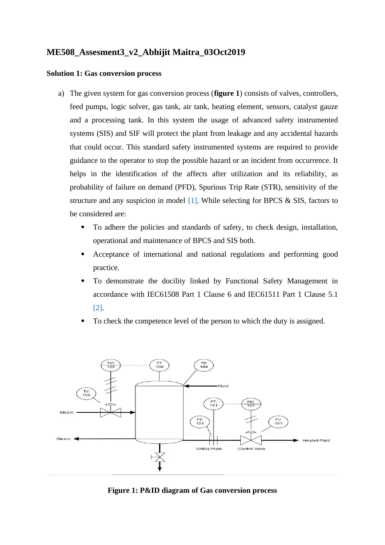
a) The given system for gas conversion process (figure 1) consists of valves, controllers,
feed pumps, logic solver, gas tank, air tank, heating element, sensors, catalyst gauze
and a processing tank. In this system the usage of advanced safety instrumented
systems (SIS) and SIF will protect the plant from leakage and any accidental hazards
that could occur. This standard safety instrumented systems are required to provide
guidance to the operator to stop the possible hazard or an incident from occurrence. It
helps in the identification of the affects after utilization and its reliability, as
probability of failure on demand (PFD), Spurious Trip Rate (STR), sensitivity of the
structure and any suspicion in model [1]. While selecting for BPCS & SIS, factors to
be considered are:
To adhere the policies and standards of safety, to check design, installation,
operational and maintenance of BPCS and SIS both.
Acceptance of international and national regulations and performing good
practice.
To demonstrate the docility linked by Functional Safety Management in
accordance with IEC61508 Part 1 Clause 6 and IEC61511 Part 1 Clause 5.1
[2].
To check the competence level of the person to which the duty is assigned.
Figure 1: P&ID diagram of Gas conversion process
Solution 1: Gas conversion process
a) The given system for gas conversion process (figure 1) consists of valves, controllers,
feed pumps, logic solver, gas tank, air tank, heating element, sensors, catalyst gauze
and a processing tank. In this system the usage of advanced safety instrumented
systems (SIS) and SIF will protect the plant from leakage and any accidental hazards
that could occur. This standard safety instrumented systems are required to provide
guidance to the operator to stop the possible hazard or an incident from occurrence. It
helps in the identification of the affects after utilization and its reliability, as
probability of failure on demand (PFD), Spurious Trip Rate (STR), sensitivity of the
structure and any suspicion in model [1]. While selecting for BPCS & SIS, factors to
be considered are:
To adhere the policies and standards of safety, to check design, installation,
operational and maintenance of BPCS and SIS both.
Acceptance of international and national regulations and performing good
practice.
To demonstrate the docility linked by Functional Safety Management in
accordance with IEC61508 Part 1 Clause 6 and IEC61511 Part 1 Clause 5.1
[2].
To check the competence level of the person to which the duty is assigned.
Figure 1: P&ID diagram of Gas conversion process
Secure Best Marks with AI Grader
Need help grading? Try our AI Grader for instant feedback on your assignments.
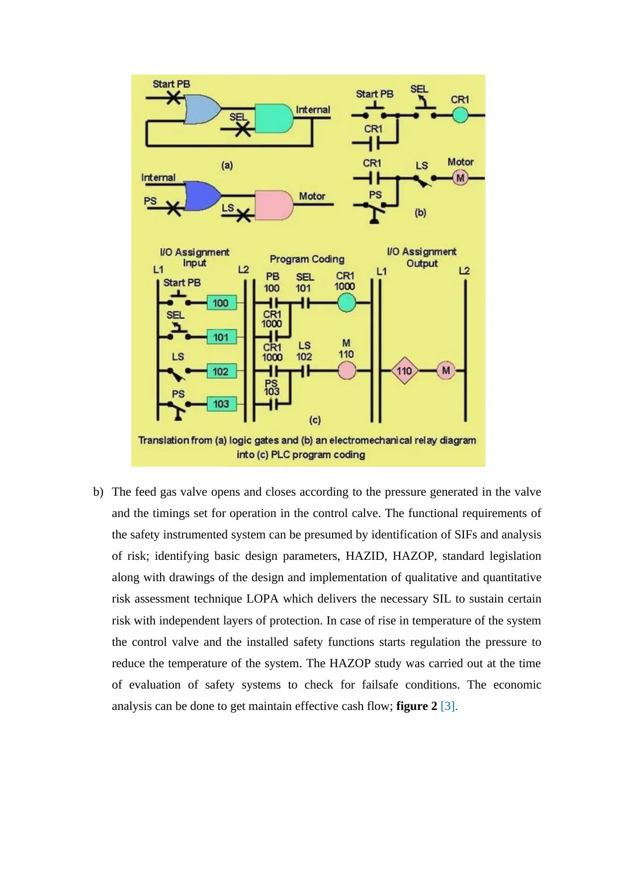
b) The feed gas valve opens and closes according to the pressure generated in the valve
and the timings set for operation in the control calve. The functional requirements of
the safety instrumented system can be presumed by identification of SIFs and analysis
of risk; identifying basic design parameters, HAZID, HAZOP, standard legislation
along with drawings of the design and implementation of qualitative and quantitative
risk assessment technique LOPA which delivers the necessary SIL to sustain certain
risk with independent layers of protection. In case of rise in temperature of the system
the control valve and the installed safety functions starts regulation the pressure to
reduce the temperature of the system. The HAZOP study was carried out at the time
of evaluation of safety systems to check for failsafe conditions. The economic
analysis can be done to get maintain effective cash flow; figure 2 [3].
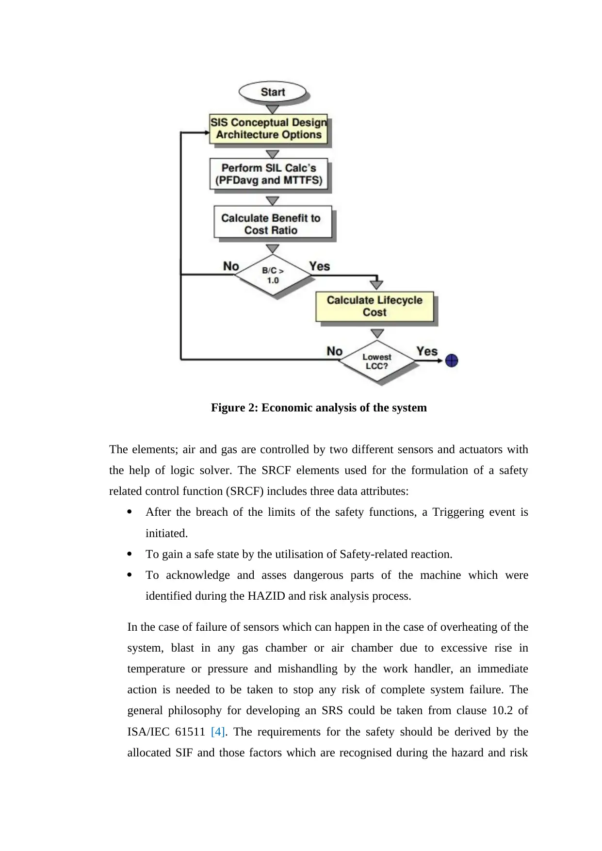
Figure 2: Economic analysis of the system
The elements; air and gas are controlled by two different sensors and actuators with
the help of logic solver. The SRCF elements used for the formulation of a safety
related control function (SRCF) includes three data attributes:
After the breach of the limits of the safety functions, a Triggering event is
initiated.
To gain a safe state by the utilisation of Safety-related reaction.
To acknowledge and asses dangerous parts of the machine which were
identified during the HAZID and risk analysis process.
In the case of failure of sensors which can happen in the case of overheating of the
system, blast in any gas chamber or air chamber due to excessive rise in
temperature or pressure and mishandling by the work handler, an immediate
action is needed to be taken to stop any risk of complete system failure. The
general philosophy for developing an SRS could be taken from clause 10.2 of
ISA/IEC 61511 [4]. The requirements for the safety should be derived by the
allocated SIF and those factors which are recognised during the hazard and risk
assessment. The SIS required for the process should be clear, accurate, easily
checked, sustainable, feasible and written in the form that could be easily
understandable by the user and could be utilised properly whenever needed.
Different nations have developed verities of methodologies to incorporate with the
assessment of the risks to the safety systems, some qualitative and some are
quantitative but no methodology is better than another.
SOLUTION 2: Functional Safety Management
a. Components of the Functional Safety Management (FSM) Plan
A key document in any IEC 61508 / ISO 26262 development project can be stated
as The Safety Plan or Functional Safety Management (FSM) Plan which specifies
how a functional safety can be assured during the development project and its
production process. The Safety Plan or Functional Safety Management (FSM)
Plan derives various strategies to check that the targeted SIL/ASIL is achieved [5].
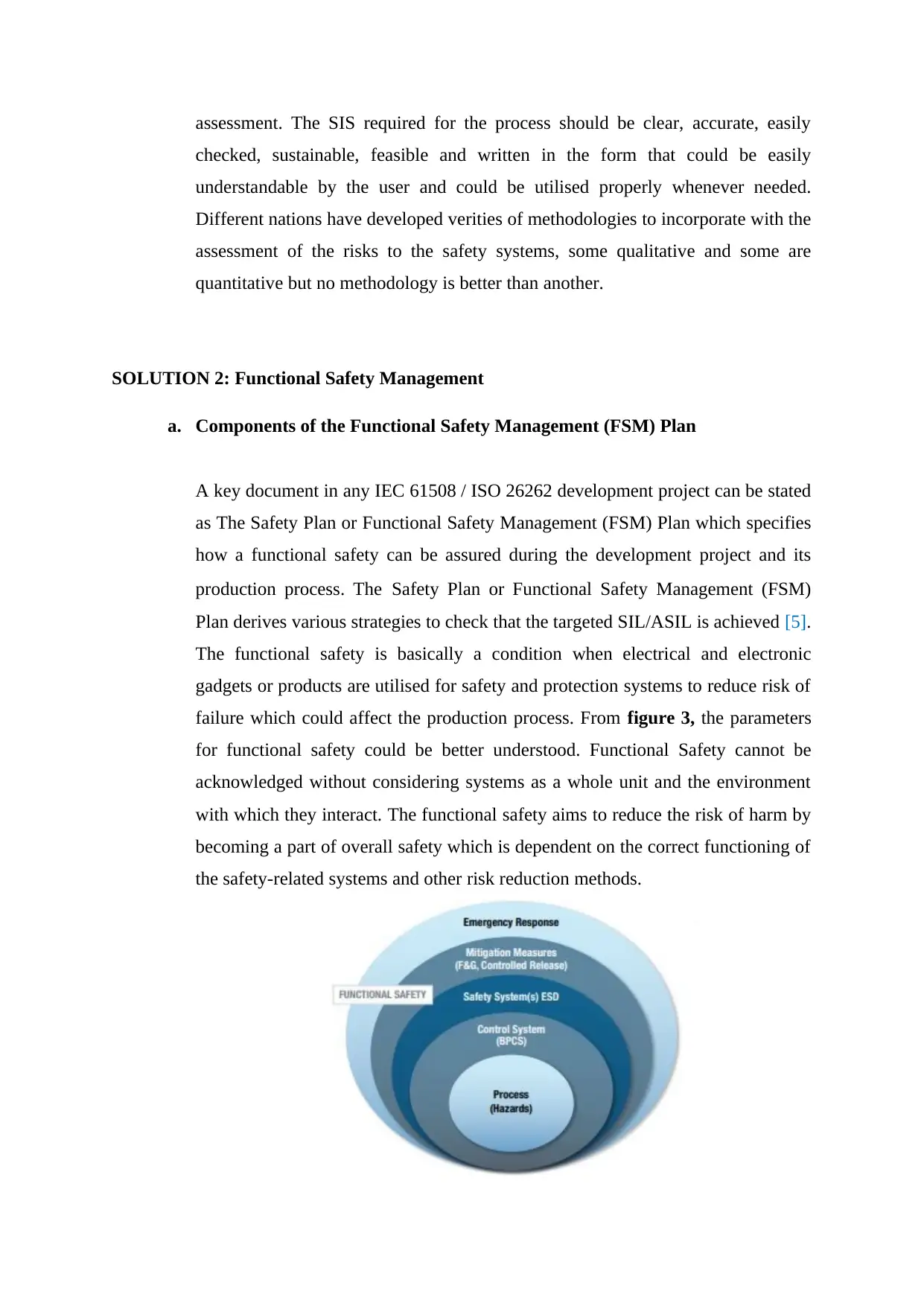
The functional safety is basically a condition when electrical and electronic
gadgets or products are utilised for safety and protection systems to reduce risk of
failure which could affect the production process. From figure 3, the parameters
for functional safety could be better understood. Functional Safety cannot be
acknowledged without considering systems as a whole unit and the environment
with which they interact. The functional safety aims to reduce the risk of harm by
becoming a part of overall safety which is dependent on the correct functioning of
the safety-related systems and other risk reduction methods.
checked, sustainable, feasible and written in the form that could be easily
understandable by the user and could be utilised properly whenever needed.
Different nations have developed verities of methodologies to incorporate with the
assessment of the risks to the safety systems, some qualitative and some are
quantitative but no methodology is better than another.
SOLUTION 2: Functional Safety Management
a. Components of the Functional Safety Management (FSM) Plan
A key document in any IEC 61508 / ISO 26262 development project can be stated
as The Safety Plan or Functional Safety Management (FSM) Plan which specifies
how a functional safety can be assured during the development project and its
production process. The Safety Plan or Functional Safety Management (FSM)
Plan derives various strategies to check that the targeted SIL/ASIL is achieved [5].
The functional safety is basically a condition when electrical and electronic
gadgets or products are utilised for safety and protection systems to reduce risk of
failure which could affect the production process. From figure 3, the parameters
for functional safety could be better understood. Functional Safety cannot be
acknowledged without considering systems as a whole unit and the environment
with which they interact. The functional safety aims to reduce the risk of harm by
becoming a part of overall safety which is dependent on the correct functioning of
the safety-related systems and other risk reduction methods.
Secure Best Marks with AI Grader
Need help grading? Try our AI Grader for instant feedback on your assignments.
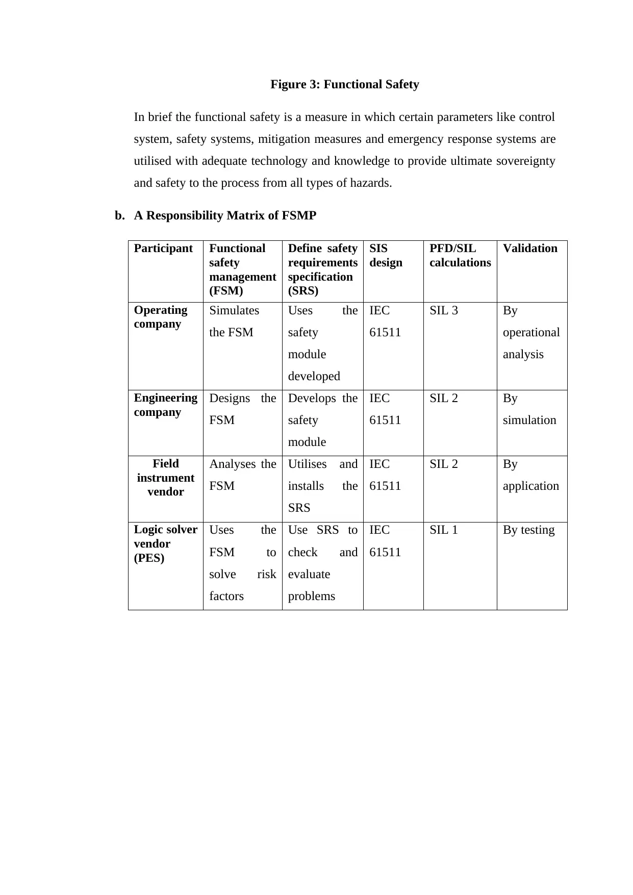
Figure 3: Functional Safety
In brief the functional safety is a measure in which certain parameters like control
system, safety systems, mitigation measures and emergency response systems are
utilised with adequate technology and knowledge to provide ultimate sovereignty
and safety to the process from all types of hazards.
b. A Responsibility Matrix of FSMP
Participant Functional
safety
management
(FSM)
Define safety
requirements
specification
(SRS)
SIS
design
PFD/SIL
calculations
Validation
Operating
company
Simulates
the FSM
Uses the
safety
module
developed
IEC
61511
SIL 3 By
operational
analysis
Engineering
company
Designs the
FSM
Develops the
safety
module
IEC
61511
SIL 2 By
simulation
Field
instrument
vendor
Analyses the
FSM
Utilises and
installs the
SRS
IEC
61511
SIL 2 By
application
Logic solver
vendor
(PES)
Uses the
FSM to
solve risk
factors
Use SRS to
check and
evaluate
problems
IEC
61511
SIL 1 By testing
REFERENCES
[1]"Safety Instrumented Systems, SIS", Iceweb.com.au, 2019. [Online]. Available:
http://www.iceweb.com.au/sis/sis_index.htm. [Accessed: 03- Oct- 2019].
[2]"Combined Basic Process Control System (BPCS) And Safety Instrumented System (SIS)
Demonstration Of Independence", 61508.org, 2019. [Online]. Available:
https://www.61508.org/index.php. [Accessed: 03- Oct- 2019].
[3]M. Scott and B. Adler, SAFETY INSTRUMENTED BURNER MANAGEMENT
SYSTEM (SI-BMS). Greenville: AE Solutions, 2019, pp. 1-5.
[4]P. Gruhn and S. Lucchini, Safety Instrumented Systems: A Life-Cycle Approach.
Research Triangle Park: The International Society of Automation, pp. 84-86.
[5]"Functional Safety Management Plan (FSM)", Exida.com, 2019. [Online]. Available:
https://www.exida.com/Resources/Term/Functional-Safety-Management-Plan-FSM.
[Accessed: 03- Oct- 2019].
1 out of 6


Your All-in-One AI-Powered Toolkit for Academic Success.
+13062052269
info@desklib.com
Available 24*7 on WhatsApp / Email
![[object Object]](/_next/static/media/star-bottom.7253800d.svg)
Unlock your academic potential
© 2024 | Zucol Services PVT LTD | All rights reserved.