ME508: Safety Instrumented Systems - Gas Conversion Process Analysis
VerifiedAdded on 2022/10/09
|6
|1194
|45
Report
AI Summary
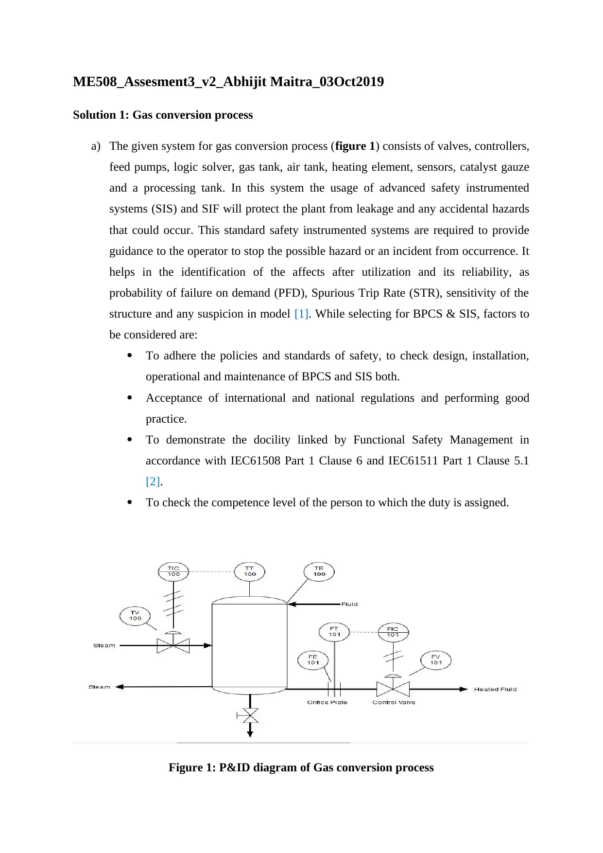
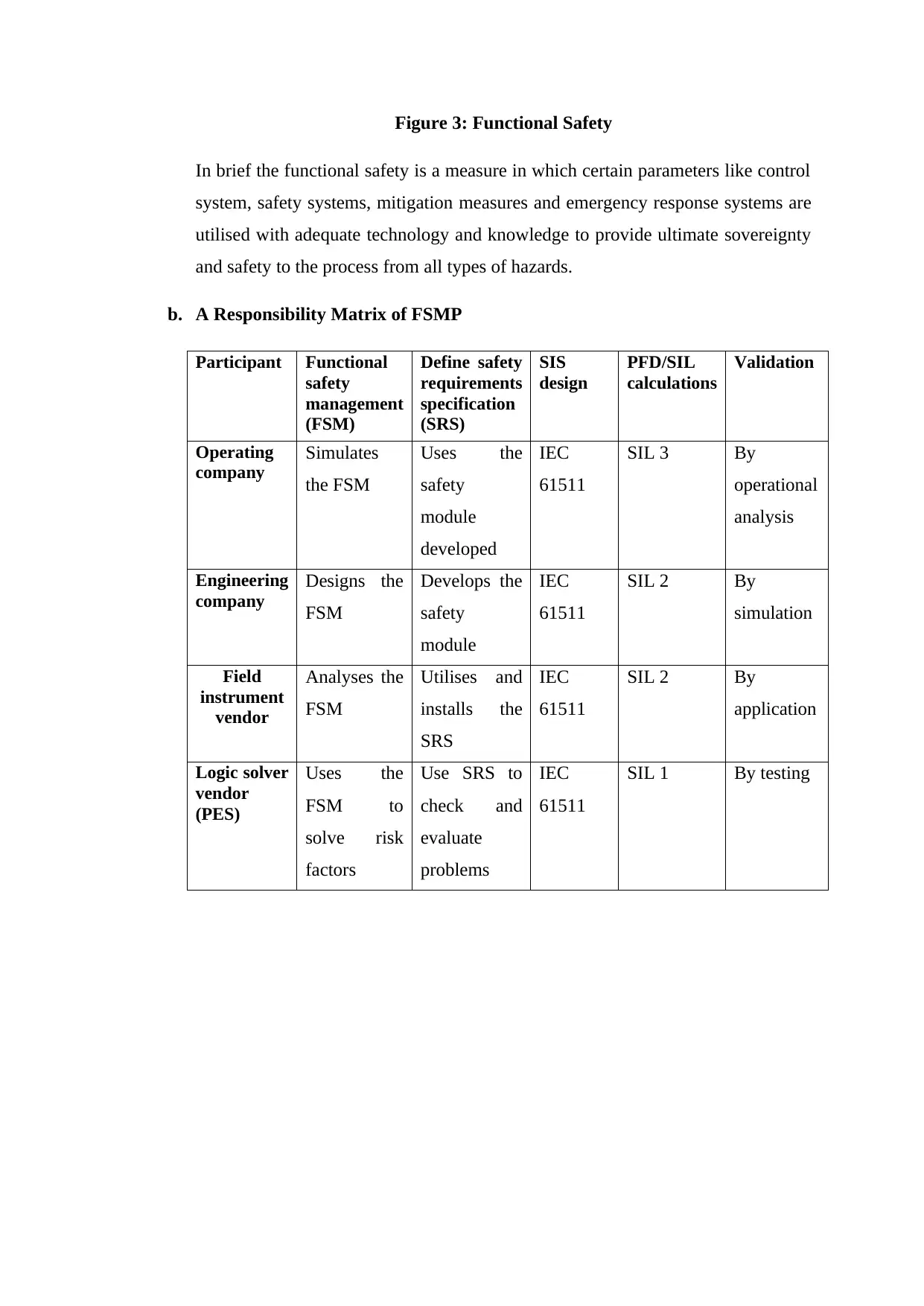
This report, prepared for the ME508 module, analyzes the safety instrumented systems (SIS) used in a gas conversion process, focusing on the application of functional safety management (FSM). The report begins with a P&ID diagram illustrating the system components, including valves, controllers, and various tanks. It emphasizes the importance of SIS in preventing hazards and outlines the factors considered when selecting BPCS and SIS, referencing international standards like IEC 61508 and IEC 61511. The analysis includes a HAZOP study to identify failsafe conditions and an economic analysis. The report details the components of the FSM plan, highlighting the importance of the Safety Plan in ensuring targeted SIL/ASIL levels. It also presents a responsibility matrix outlining the roles of various stakeholders in the FSM process. The report concludes by emphasizing the need for clear, accurate, and easily understandable safety requirements derived from hazard and risk assessments.
1 out of 6


Your All-in-One AI-Powered Toolkit for Academic Success.
+13062052269
info@desklib.com
Available 24*7 on WhatsApp / Email
![[object Object]](/_next/static/media/star-bottom.7253800d.svg)
Copyright © 2020–2026 A2Z Services. All Rights Reserved. Developed and managed by ZUCOL.