Wind Turbine Gearbox Design Project Report - Mechanical Engineering
VerifiedAdded on 2023/05/30
|10
|1907
|128
Report
AI Summary
This report presents a comprehensive analysis of a wind turbine gearbox design project, focusing on the mechanical engineering aspects. It begins with an introduction to wind turbine technology and the critical role of the gearbox in converting wind energy into electricity. The report details the design specifications, including gear configuration, shaft design, and the components involved in the gearbox. It explores the use of a compound epicyclical gear configuration with three planetary gears meshing with a central sun gear, detailing torque calculations and the significance of shaft design using steel for its strength and corrosion resistance. The report includes diagrams illustrating the gearbox and its components, emphasizing the importance of gearbox specifications for optimizing wind turbine performance and minimizing maintenance costs. It further describes the components and structures of the gearbox, including the planetary and parallel gear stages, and the dynamic responses of the components. The report also provides equations used to calculate relative displacements and mesh forces within the gearbox, considering factors like backlash and errors in static transmission. Newton's law is applied to derive motion equations for the planet carrier, sun pinions, and planet gears. The report concludes with a final design illustration and a bibliography of relevant resources.
Description of the gearbox design 1
DESCRIPTION OF THE GEARBOX DESIGN
By Name
Course
Instructor
Institution
Location
Date
DESCRIPTION OF THE GEARBOX DESIGN
By Name
Course
Instructor
Institution
Location
Date
Paraphrase This Document
Need a fresh take? Get an instant paraphrase of this document with our AI Paraphraser
Description of the gearbox design 2
Gear design
This project will use a compound epicyclical gear configuration that has three planetary gears
that mesh a central sun gear. The planet gears are usually a section of a two gear grip on the
similar shaft or at the centre as second planet gears. A carrier holds the planet gear and its
support bearings thus rotating along the mid axis of the unit [1].
The recommended gear-ratio that is recommended to ranges at intervals of 6:1 and 25:1.
The force transferred by each gear was evaluated as:
Torque =power/angular velocity
There is also need to determine the gear box equivalent running time that might be asa result
of unsteady loading of the gearbox.
Shaft design
The shaft in this gearbox design comprise of main shaft that act as a links between the rotor
and the gearbox. The number of shafts needed are based on the gear configuration. In a
gearbox the main forces that act upon shafts are radial and tangential forces as a result of the
spur gear [2].
The torque on the shaft is given by:
Torque= power/angular velocity
The shaft should be steel in nature because of the tensile strength, economical, and corrosion
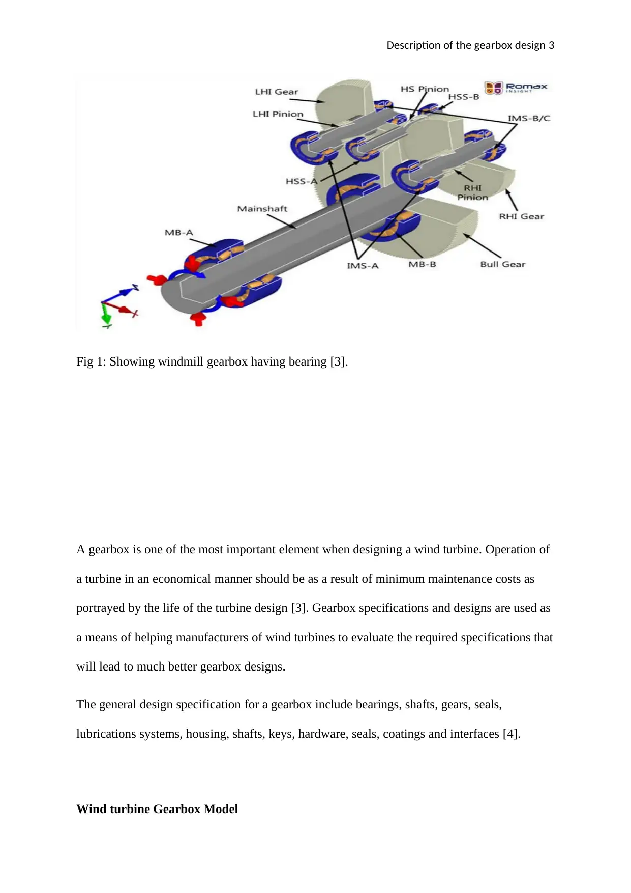
resistance. The gearbox of the windmill with the bearing can be illustrated using the
following diagram;
Description of the gearbox design 3
Fig 1: Showing windmill gearbox having bearing [3].
A gearbox is one of the most important element when designing a wind turbine. Operation of
a turbine in an economical manner should be as a result of minimum maintenance costs as
portrayed by the life of the turbine design [3]. Gearbox specifications and designs are used as
a means of helping manufacturers of wind turbines to evaluate the required specifications that
will lead to much better gearbox designs.
The general design specification for a gearbox include bearings, shafts, gears, seals,
lubrications systems, housing, shafts, keys, hardware, seals, coatings and interfaces [4].
Wind turbine Gearbox Model
⊘ This is a preview!⊘
Do you want full access?
Subscribe today to unlock all pages.

Trusted by 1+ million students worldwide
Description of the gearbox design 4
Components and structures
The proposed gearbox mainly has 3 gear stages namely; the minimum speed planetary stage,
the medium and top-speed parallel gear stage. According to this theory, in most cases the
bearings of the main shaft absorb the air dynamic loading and hence influence the driving
speed without affecting the gear teeth [5]. Hence, this proposed model’s input load is only
torsional in nature that is to be directly applied to the planet carrier arm, which is used to
transmit the load to sun pinion and also planet gears. The gearbox is in this case assumed to
be uncoupled with the non-torsional loads.
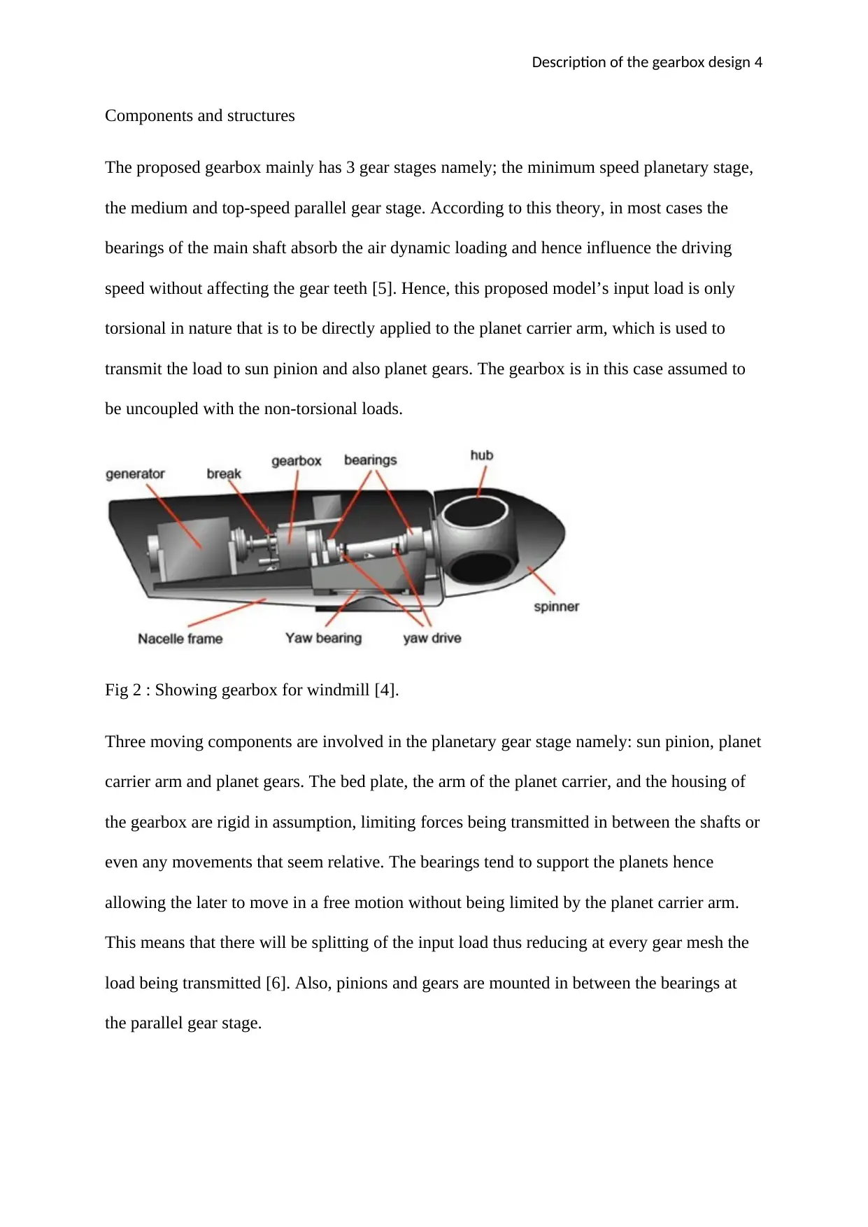
Fig 2 : Showing gearbox for windmill [4].
Three moving components are involved in the planetary gear stage namely: sun pinion, planet
carrier arm and planet gears. The bed plate, the arm of the planet carrier, and the housing of
the gearbox are rigid in assumption, limiting forces being transmitted in between the shafts or
even any movements that seem relative. The bearings tend to support the planets hence
allowing the later to move in a free motion without being limited by the planet carrier arm.
This means that there will be splitting of the input load thus reducing at every gear mesh the
load being transmitted [6]. Also, pinions and gears are mounted in between the bearings at
the parallel gear stage.
Paraphrase This Document
Need a fresh take? Get an instant paraphrase of this document with our AI Paraphraser
Description of the gearbox design 5
This prototype can in any case be used in predicting dynamic responses of the components of
the gearbox. Wind fluctuations because both low and high frequency wind excitations that
must be considered due to errors in static transmission. The wind causes fluctuations in
external excitations, while errors in static transmission is as a result of the kinetic errors
during meshing of gear pairs. Other factors that must be considered include damping,
stiffness of the bearing, gear backlash and time varying mesh stiffness.
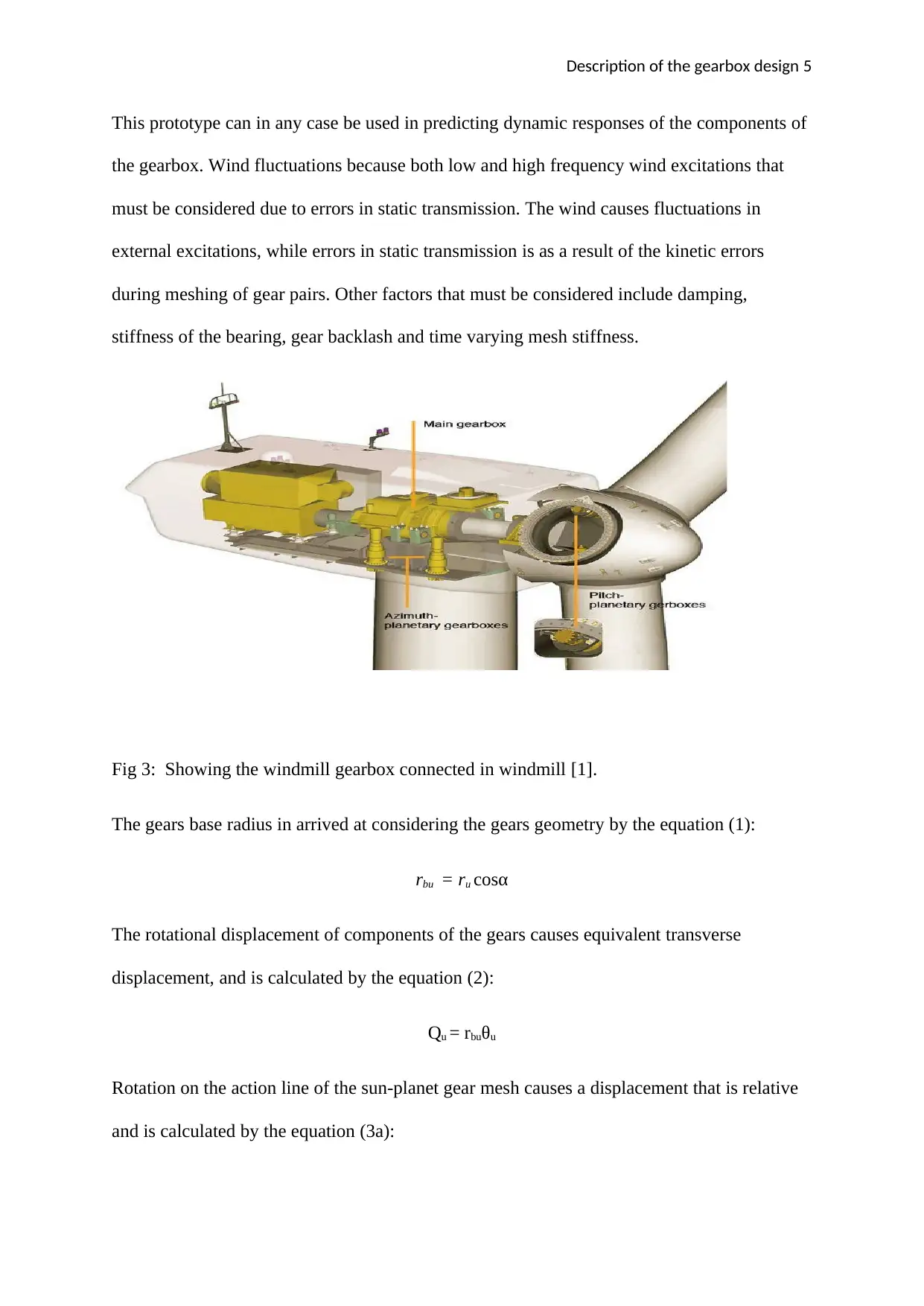
Fig 3: Showing the windmill gearbox connected in windmill [1].
The gears base radius in arrived at considering the gears geometry by the equation (1):
rbu = ru cosα
The rotational displacement of components of the gears causes equivalent transverse
displacement, and is calculated by the equation (2):
Qu = rbuθu
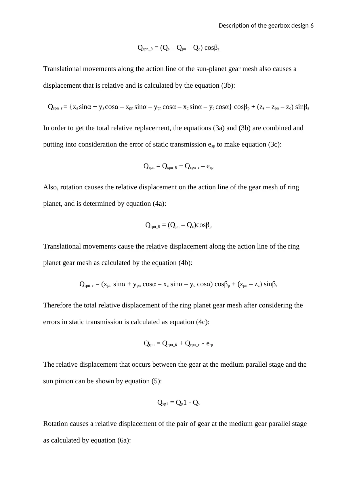
Rotation on the action line of the sun-planet gear mesh causes a displacement that is relative
and is calculated by the equation (3a):
Description of the gearbox design 6
Qspn_θ = (Qs – Qpn – Qc) cosβs
Translational movements along the action line of the sun-planet gear mesh also causes a
displacement that is relative and is calculated by the equation (3b):
Qspn_r = {xs sinα + ys cosα – xpn sinα – ypn cosα – xc sinα – yc cosα} cosβp + (zs – zpn – zc) sinβs
In order to get the total relative replacement, the equations (3a) and (3b) are combined and
putting into consideration the error of static transmission esp to make equation (3c):
Qspn = Qspn_θ + Qspn_r – esp
Also, rotation causes the relative displacement on the action line of the gear mesh of ring
planet, and is determined by equation (4a):
Qrpn_θ = (Qpn – Qc)cosβp
Translational movements cause the relative displacement along the action line of the ring
planet gear mesh as calculated by the equation (4b):
Qrpn_r = (xpn sinα + ypn cosα – xc sinα – yc cosα) cosβp + (zpn – zc) sinβs
Therefore the total relative displacement of the ring planet gear mesh after considering the
errors in static transmission is calculated as equation (4c):
Qrpn = Qrpn_θ + Qrpn_r - erp
The relative displacement that occurs between the gear at the medium parallel stage and the
sun pinion can be shown by equation (5):
Qsg1 = Qg1 - Qs
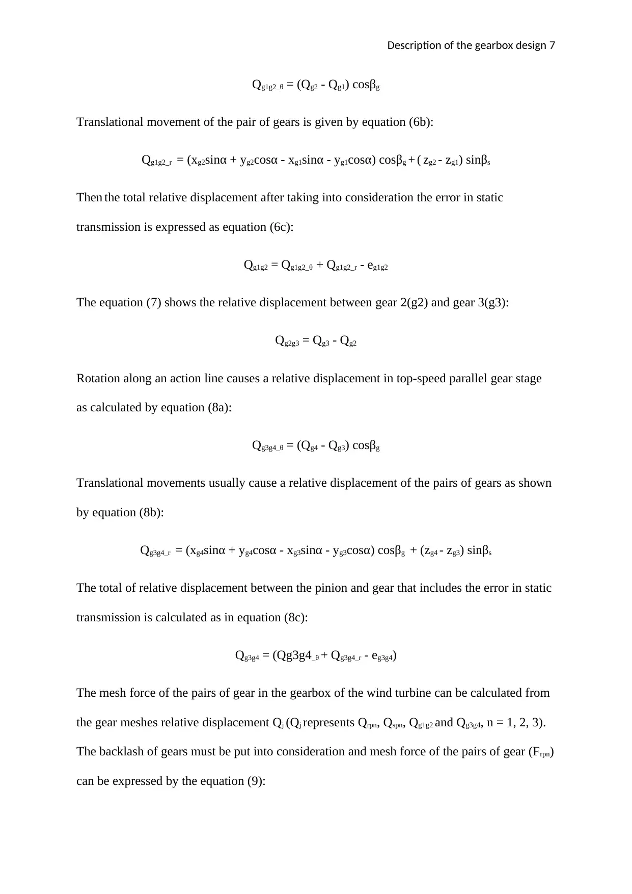
Rotation causes a relative displacement of the pair of gear at the medium gear parallel stage
as calculated by equation (6a):
⊘ This is a preview!⊘
Do you want full access?
Subscribe today to unlock all pages.

Trusted by 1+ million students worldwide
Description of the gearbox design 7
Qg1g2_θ = (Qg2 - Qg1) cosβg
Translational movement of the pair of gears is given by equation (6b):
Qg1g2_r = (xg2sinα + yg2cosα - xg1sinα - yg1cosα) cosβg + ( zg2 - zg1) sinβs
Then the total relative displacement after taking into consideration the error in static
transmission is expressed as equation (6c):
Qg1g2 = Qg1g2_θ + Qg1g2_r - eg1g2
The equation (7) shows the relative displacement between gear 2(g2) and gear 3(g3):
Qg2g3 = Qg3 - Qg2
Rotation along an action line causes a relative displacement in top-speed parallel gear stage
as calculated by equation (8a):
Qg3g4_θ = (Qg4 - Qg3) cosβg
Translational movements usually cause a relative displacement of the pairs of gears as shown
by equation (8b):
Qg3g4_r = (xg4sinα + yg4cosα - xg3sinα - yg3cosα) cosβg + (zg4 - zg3) sinβs
The total of relative displacement between the pinion and gear that includes the error in static
transmission is calculated as in equation (8c):
Qg3g4 = (Qg3g4_θ + Qg3g4_r - eg3g4)
The mesh force of the pairs of gear in the gearbox of the wind turbine can be calculated from
the gear meshes relative displacement Qj (Qj represents Qrpn, Qspn, Qg1g2 and Qg3g4, n = 1, 2, 3).
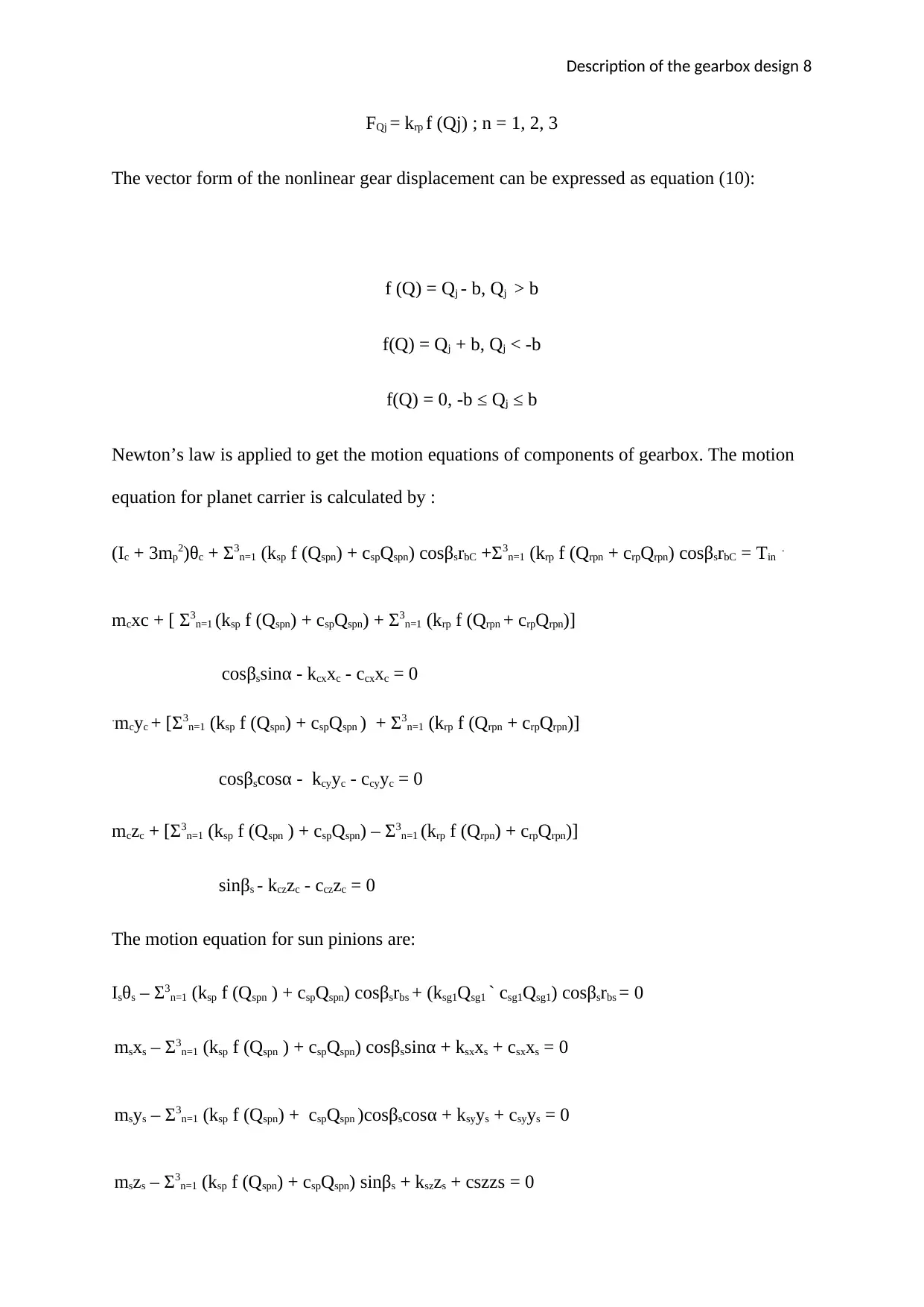
The backlash of gears must be put into consideration and mesh force of the pairs of gear (Frpn)
can be expressed by the equation (9):
Paraphrase This Document
Need a fresh take? Get an instant paraphrase of this document with our AI Paraphraser
Description of the gearbox design 8
FQj = krp f (Qj) ; n = 1, 2, 3
The vector form of the nonlinear gear displacement can be expressed as equation (10):
f (Q) = Qj - b, Qj ˃ b
f(Q) = Qj + b, Qj ˂ -b
f(Q) = 0, -b ≤ Qj ≤ b
Newton’s law is applied to get the motion equations of components of gearbox. The motion
equation for planet carrier is calculated by :
(Ic + 3mp2)θc + Ʃ3n=1 (ksp f (Qspn) + cspQspn) cosβsrbC +Ʃ3n=1 (krp f (Qrpn + crpQrpn) cosβsrbC = Tin .
mcxc + [ Ʃ3n=1 (ksp f (Qspn) + cspQspn) + Ʃ3n=1 (krp f (Qrpn + crpQrpn)]
cosβssinα - kcxxc - ccxxc = 0
.mcyc + [Ʃ3n=1 (ksp f (Qspn) + cspQspn ) + Ʃ3n=1 (krp f (Qrpn + crpQrpn)]
cosβscosα - kcyyc - ccyyc = 0
mczc + [Ʃ3n=1 (ksp f (Qspn ) + cspQspn) – Ʃ3n=1 (krp f (Qrpn) + crpQrpn)]
sinβs - kczzc - cczzc = 0
The motion equation for sun pinions are:
Isθs – Ʃ3n=1 (ksp f (Qspn ) + cspQspn) cosβsrbs + (ksg1Qsg1 ` csg1Qsg1) cosβsrbs = 0
msxs – Ʃ3n=1 (ksp f (Qspn ) + cspQspn) cosβssinα + ksxxs + csxxs = 0
msys – Ʃ3n=1 (ksp f (Qspn) + cspQspn )cosβscosα + ksyys + csyys = 0
mszs – Ʃ3n=1 (ksp f (Qspn) + cspQspn) sinβs + kszzs + cszzs = 0
Description of the gearbox design 9
The motion equation for the planet gears are as given above.
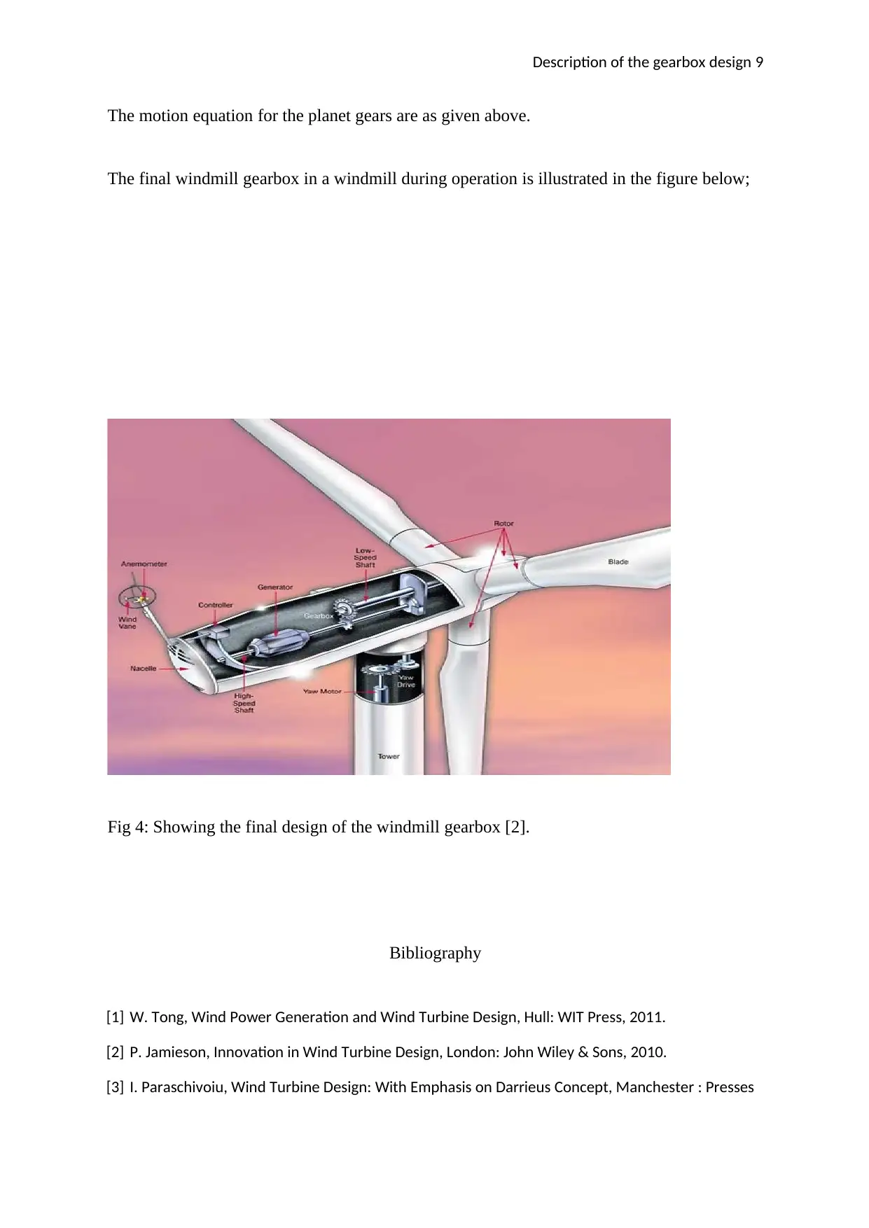
The final windmill gearbox in a windmill during operation is illustrated in the figure below;
Fig 4: Showing the final design of the windmill gearbox [2].
Bibliography
[1] W. Tong, Wind Power Generation and Wind Turbine Design, Hull: WIT Press, 2011.
[2] P. Jamieson, Innovation in Wind Turbine Design, London: John Wiley & Sons, 2010.
[3] I. Paraschivoiu, Wind Turbine Design: With Emphasis on Darrieus Concept, Manchester : Presses
⊘ This is a preview!⊘
Do you want full access?
Subscribe today to unlock all pages.

Trusted by 1+ million students worldwide
Description of the gearbox design 10
inter Polytechnique, 2012.
[4] M. Adaramola, Wind Turbine Technology: Principles and Design, Stoke: CRC Press, 2012.
[5] L. Silk, Wind Turbine Technology and Design, Chicago: Jones & Bartlett Publishers, 2012.
[6] D. Wood, Small Wind Turbines: Analysis, Design, and Application, London: Springer, 2011.
1 out of 10
Your All-in-One AI-Powered Toolkit for Academic Success.
+13062052269
info@desklib.com
Available 24*7 on WhatsApp / Email
![[object Object]](/_next/static/media/star-bottom.7253800d.svg)
Unlock your academic potential
Copyright © 2020–2026 A2Z Services. All Rights Reserved. Developed and managed by ZUCOL.