Contents Abstract:................................................................................................................................................3 Research:...............................................................................................................................................3 Modelling:.............................................................................................................................................3 Testing and Verification:........................................................................................................................5 Discussion of Results :...........................................................................................................................9 Additional Work :...................................................................................................................................9 Conclusion :...........................................................................................................................................9 References :.........................................................................................................................................10 MATLAB Code :....................................................................................................................................11
Abstract: The domain of earthquake engineering includes the concepts of Geotechnical engineering and the structural engineering. It helps to protect the buildings and structures from natural calamities like earthquake. The study of seismic waves is necessary for various structures to design methods to save them. Their sub – parts need to be designed in such a way that they can be protected from the seismic wave effect [1]. Research: The second order equation of motion is considered with a natural frequency ( wn ) and a damping ratio ‘ξ’. The excitation given to the system is Üg ( t ). The steps followed for sDOF are as follows : The online tables are used to determine the total stiffness of the structure ( k ) , the dead ( self weight ) and live load on the structure. On the basis of DL and LL, the total mass (m) is determined [2]. The natural frequency ( wn ) is found using the value of the natural period ( Tn ). Initially, the excitation is defined ( Üg ( t ) ). The Fourier transform Üg ( w ) is found. The transfer function of the system is determined and the range of frequency is also found [3]. H ( w ) is defined in MATLAB and the response is found in frequency domain U(w). It is converted to u ( t ). Finally, the base shear is found for the structure along with the peak absolute values. Modelling: Here, i = 11 and n = 2 Single Degree freedom : Self weight concrete = 2400 kN / m3 x volume = DL Self weight steel = 7850 kN / m3 x volume = DL G = dead load Q = Live load ( from online table ) Steel frame includes beam and column. Another part is concrete slab. G, concrete slab : L = ( 2 - 1 ) x 4 = 4
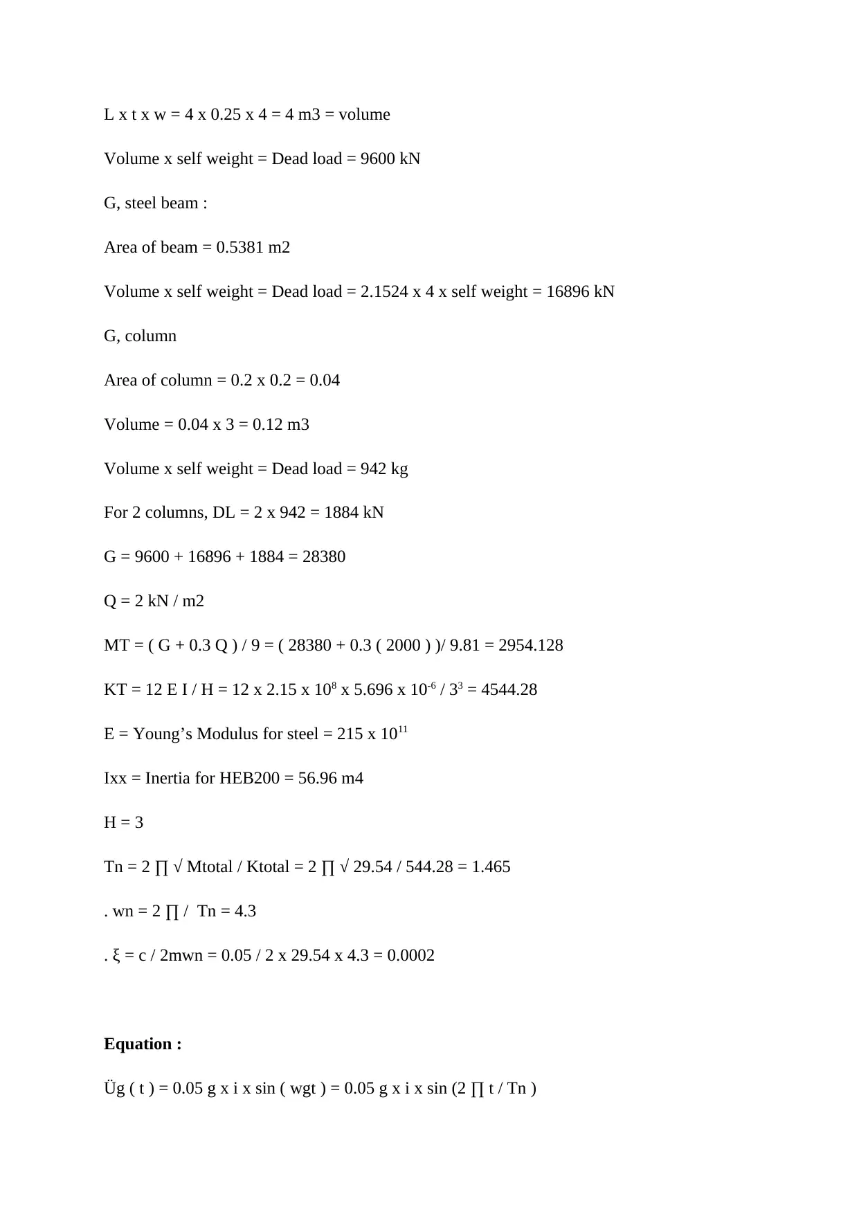
L x t x w = 4 x 0.25 x 4 = 4 m3 = volume Volume x self weight = Dead load = 9600 kN G, steel beam : Area of beam = 0.5381 m2 Volume x self weight = Dead load = 2.1524 x 4 x self weight = 16896 kN G, column Area of column = 0.2 x 0.2 = 0.04 Volume = 0.04 x 3 = 0.12 m3 Volume x self weight = Dead load = 942 kg For 2 columns, DL = 2 x 942 = 1884 kN G = 9600 + 16896 + 1884 = 28380 Q = 2 kN / m2 MT = ( G + 0.3 Q ) / 9 = ( 28380 + 0.3 ( 2000 ) )/ 9.81 = 2954.128 KT = 12 E I / H = 12 x 2.15 x 108x 5.696 x 10-6/ 33= 4544.28 E = Young’s Modulus for steel = 215 x 1011 Ixx = Inertia for HEB200 = 56.96 m4 H = 3 Tn = 2 ∏ √ Mtotal / Ktotal = 2 ∏ √ 29.54 / 544.28 = 1.465 . wn = 2 ∏ / Tn = 4.3 . ξ = c / 2mwn = 0.05 / 2 x 29.54 x 4.3 = 0.0002 Equation : Üg ( t ) = 0.05 g x i x sin ( wgt ) = 0.05 g x i x sin (2 ∏ t / Tn )
Paraphrase This Document
Need a fresh take? Get an instant paraphrase of this document with our AI Paraphraser
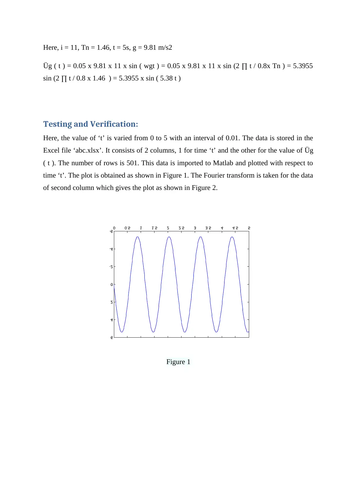
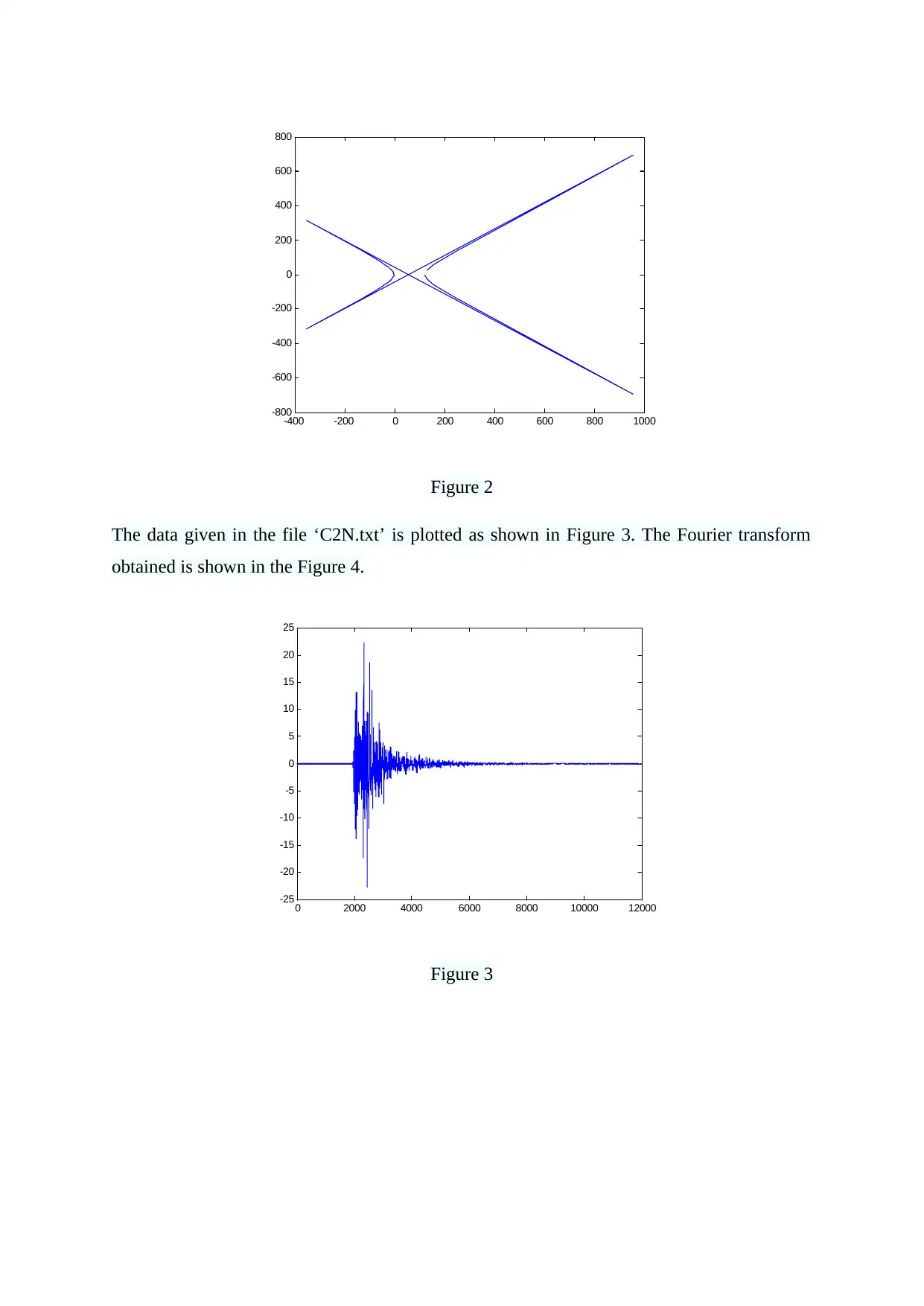
Here, i = 11, Tn = 1.46, t = 5s, g = 9.81 m/s2 Üg ( t ) = 0.05 x 9.81 x 11 x sin ( wgt ) = 0.05 x 9.81 x 11 x sin (2 ∏ t / 0.8x Tn ) = 5.3955 sin (2 ∏ t / 0.8 x 1.46 ) = 5.3955 x sin ( 5.38 t ) Testing and Verification: Here, the value of ‘t’ is varied from 0 to 5 with an interval of 0.01. The data is stored in the Excel file ‘abc.xlsx’. It consists of 2 columns, 1 for time ‘t’ and the other for the value of Üg ( t ). The number of rows is 501. This data is imported to Matlab and plotted with respect to time ‘t’. The plot is obtained as shown in Figure 1. The Fourier transform is taken for the data of second column which gives the plot as shown in Figure 2. Figure 1
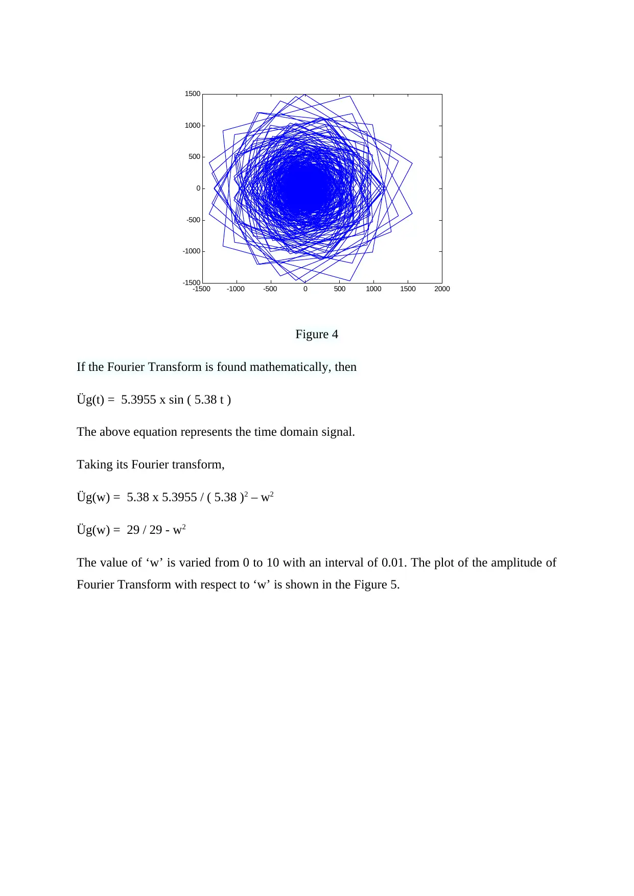
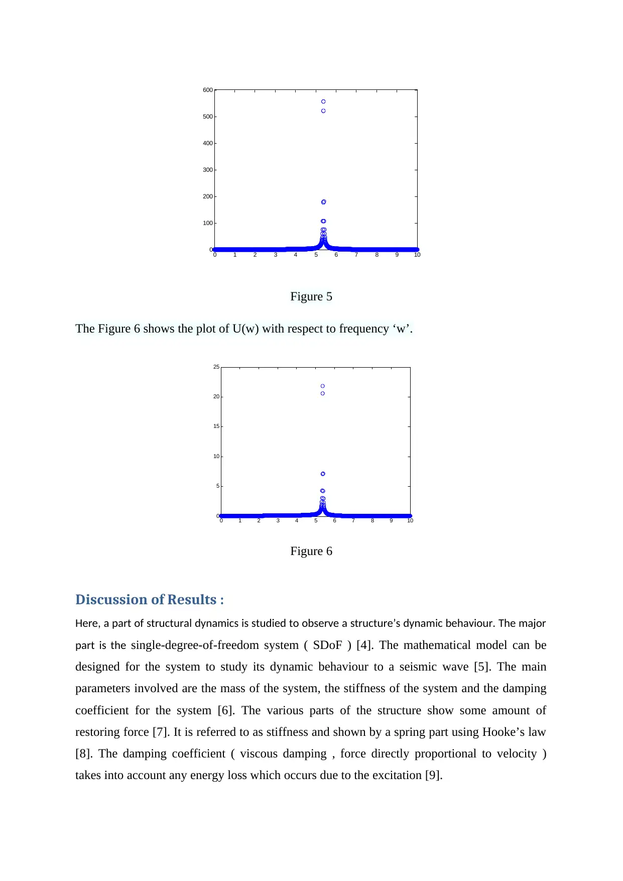
-400-20002004006008001000 -800 -600 -400 -200 0 200 400 600 800 Figure 2 The data given in the file ‘C2N.txt’ is plotted as shown in Figure 3. The Fourier transform obtained is shown in the Figure 4. 020004000600080001000012000 -25 -20 -15 -10 -5 0 5 10 15 20 25 Figure 3
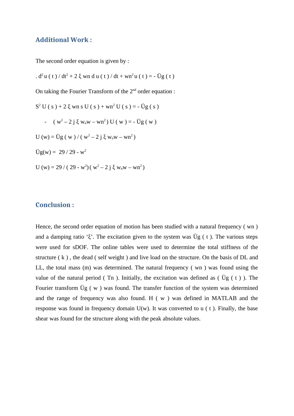
-1500-1000-5000500100015002000 -1500 -1000 -500 0 500 1000 1500 Figure 4 If the Fourier Transform is found mathematically, then Üg(t) = 5.3955 x sin ( 5.38 t ) The above equation represents the time domain signal. Taking its Fourier transform, Üg(w) = 5.38 x 5.3955 / ( 5.38 )2– w2 Üg(w) = 29 / 29 - w2 The value of ‘w’ is varied from 0 to 10 with an interval of 0.01. The plot of the amplitude of Fourier Transform with respect to ‘w’ is shown in the Figure 5.
Secure Best Marks with AI Grader
Need help grading? Try our AI Grader for instant feedback on your assignments.
012345678910 0 100 200 300 400 500 600 Figure 5 The Figure 6 shows the plot of U(w) with respect to frequency ‘w’. 012345678910 0 5 10 15 20 25 Figure 6 Discussion of Results : Here, a part of structural dynamics is studied to observe a structure’s dynamic behaviour. The major part is thesingle-degree-of-freedom system ( SDoF ) [4]. The mathematical model can be designed for the system to study its dynamic behaviour to a seismic wave [5]. The main parameters involved are the mass of the system, the stiffness of the system and the damping coefficient for the system [6]. The various parts of the structure show some amount of restoring force [7]. It is referred to as stiffness and shown by a spring part using Hooke’s law [8]. The damping coefficient ( viscous damping , force directly proportional to velocity ) takes into account any energy loss which occurs due to the excitation [9].
Additional Work : The second order equation is given by : . d2u ( t ) / dt2+ 2 ξ wn d u ( t ) / dt + wn2u ( t ) = - Üg ( t ) On taking the Fourier Transform of the 2ndorder equation : S2U ( s ) + 2 ξ wn s U ( s ) + wn2U ( s ) = - Üg ( s ) -( w2– 2 j ξ wnw – wn2) U ( w ) = - Üg ( w ) U (w) = Üg ( w ) / ( w2– 2 j ξ wnw – wn2) Üg(w) = 29 / 29 - w2 U (w) = 29 / ( 29 - w2)( w2– 2 j ξ wnw – wn2) Conclusion : Hence, the second order equation of motion has been studied with a natural frequency ( wn ) and a damping ratio ‘ξ’. The excitation given to the system was Üg ( t ). The various steps were used for sDOF. The online tables were used to determine the total stiffness of the structure ( k ) , the dead ( self weight ) and live load on the structure. On the basis of DL and LL, the total mass (m) was determined. The natural frequency ( wn ) was found using the value of the natural period ( Tn ). Initially, the excitation was defined as ( Üg ( t ) ). The Fourier transform Üg ( w ) was found. The transfer function of the system was determined and the range of frequency was also found. H ( w ) was defined in MATLAB and the response was found in frequency domain U(w). It was converted to u ( t ). Finally, the base shear was found for the structure along with the peak absolute values.
References : [1] Li, H.N., Qu, C., Huo, L. and Nagarajaiah, S., 2016. Equivalent bilinear elastic single degreeoffreedomsystemofmulti-degreeoffreedomstructurewithnegative stiffness.Journal of Sound and Vibration,365, pp.1-14. [2] Cormie, D. and Arkinstall, M., 2012. SDOF Isn't Dead—The Role of Single Degree of Freedom Analysis in the Design of Columns against Close-In Blast. InStructures Congress 2012(pp. 114-125). [3] Figuli, L. and Papán, D., 2014. Single degree of freedom analysis of steel beams under blastloading.InAppliedmechanicsandmaterials(Vol.617,pp.92-95).TransTech Publications Ltd. [4] Gavin, H.P., 2014. Vibrations of single degree of freedom systems.CEE Structural Dynamics. [5] Ikago, K., Saito, K. and Inoue, N., 2012. Seismic control of single‐degree‐of‐freedom structureusingtunedviscousmassdamper.EarthquakeEngineering&Structural Dynamics,41(3), pp.453-474. [6] Dragos, J. and Wu, C., 2015. Single-degree-of-freedom approach to incorporate axial load effectsonpressureimpulsecurvesforsteelcolumns.JournalofEngineering Mechanics,141(1), p.04014098. [7] Lee, K. and Shin, J., 2016. Equivalent single-degree-of-freedom analysis for blast- resistant design.International Journal of Steel Structures,16(4), pp.1263-1271. [8] Gao, C., Zhang, W., Liu, Y., Ye, Z. and Jiang, Y., 2015. Numerical study on the correlation of transonic single-degree-of-freedom flutter and buffet.Science China Physics, Mechanics & Astronomy,58(8), p.84701.
Paraphrase This Document
Need a fresh take? Get an instant paraphrase of this document with our AI Paraphraser
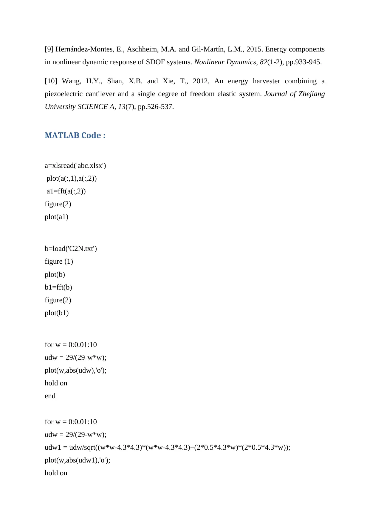
[9] Hernández-Montes, E., Aschheim, M.A. and Gil-Martín, L.M., 2015. Energy components in nonlinear dynamic response of SDOF systems.Nonlinear Dynamics,82(1-2), pp.933-945. [10]Wang,H.Y.,Shan,X.B.andXie,T.,2012.Anenergyharvestercombininga piezoelectric cantilever and a single degree of freedom elastic system.Journal of Zhejiang University SCIENCE A,13(7), pp.526-537. MATLAB Code : a=xlsread('abc.xlsx') plot(a(:,1),a(:,2)) a1=fft(a(:,2)) figure(2) plot(a1) b=load('C2N.txt') figure (1) plot(b) b1=fft(b) figure(2) plot(b1) for w = 0:0.01:10 udw = 29/(29-w*w); plot(w,abs(udw),'o'); hold on end for w = 0:0.01:10 udw = 29/(29-w*w); udw1 = udw/sqrt((w*w-4.3*4.3)*(w*w-4.3*4.3)+(2*0.5*4.3*w)*(2*0.5*4.3*w)); plot(w,abs(udw1),'o'); hold on