Geotechnical Engineering
VerifiedAdded on 2023/06/04
|6
|605
|191
AI Summary
This article covers the determination of cohesion and angle of frictional resistance, composition of soil, shear strength determination, coefficient of permeability in constant head permeability, flow rate in an aquifer, and references. The subject is Geotechnical Engineering and the content is relevant for students pursuing courses in soil mechanics and foundation engineering.
Contribute Materials
Your contribution can guide someone’s learning journey. Share your
documents today.
Running head: GEOTECHNICAL ENGINEERING 1
Geotechnical Engineering
Student’s Name
Institutional Affiliation
Geotechnical Engineering
Student’s Name
Institutional Affiliation
Secure Best Marks with AI Grader
Need help grading? Try our AI Grader for instant feedback on your assignments.
GEOTECHNICAL ENGINEERING 2
Geotechnical Engineering
1. a Determining the cohesion, c and angle of frictional resistance, φ
Test number Normal stress Shear stress
1 94.83 94.44
2 194.84 144.44
3 294.85 194.44
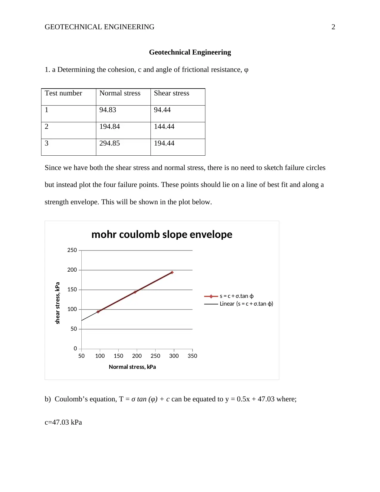
Since we have both the shear stress and normal stress, there is no need to sketch failure circles
but instead plot the four failure points. These points should lie on a line of best fit and along a
strength envelope. This will be shown in the plot below.
50 100 150 200 250 300 350
0
50
100
150
200
250
mohr coulomb slope envelope
s = c + σ.tan ϕ
Linear (s = c + σ.tan ϕ)
Normal stress, kPa
shear stress, kPa
b) Coulomb’s equation, Τ = σ tan (φ) + c can be equated to y = 0.5x + 47.03 where;
c=47.03 kPa
GEOTECHNICAL ENGINEERING 3
φ= 42°
c) Composition of the above soil given the parameters. This is a c-φ soil. This means that this
soil contains clay and some amounts of sand, gravel and silt. It therefore contains inorganic
matter since it is sand with clay binds. This soil is less liable to failure since it has both frictional
resistance and cohesion.
d) From coulomb’s equation, Τ = σ tan (φ) + c the elements on the right should be equal to those
on the left. Failure will occur in this case since normal stress, 200 kPa exceeds shear stress, 150
kPa. The resultant of this when plotted will give a small cohesion and a big angle of frictional
resistance. Soil will fail if frictional resistance exceeds shear strength. However, in some trial
tests for shear strength tests, the normal stress exceeds sear stress but not for this big margin.
e) Shear strength determination in the vane test given the torque, width and height of the vane.
Shear strength is determined by the following formula:
T=CU
π d2 H
2 (1+ D
3 H )
Where,
T= Torque=75Nm
D=width of the vane=75mm
H=height of the vane=100mm
Substituting the above variables gives
GEOTECHNICAL ENGINEERING 4
75=CU
π ¿ 0.0752∗0.1
2 (1+ 0.075
3∗0.1 )
75=CUπ 9
32000 (1.25)
Solving for CU gives
CU= 75∗25600
9 π
CU=67,906.1N/m2
CU=67.91kP
2. a Determining the coefficient of permeability in Constant head permeability
Diameter of permeameter, d= 63 mm
Distance between manometer tubes, L=145mm
Head difference=99mm
K= Q
Ait
A= π D2
4 = π∗632
4 =3117.2 mm2
q= Q
t = 2650
5∗60 =8.83 ml/s =8830 mm/s
k= qL
A h = = 8830∗145
3117.2∗99 =4.15mm/s
Secure Best Marks with AI Grader
Need help grading? Try our AI Grader for instant feedback on your assignments.
GEOTECHNICAL ENGINEERING 5
k=4.15*10-4 m/s
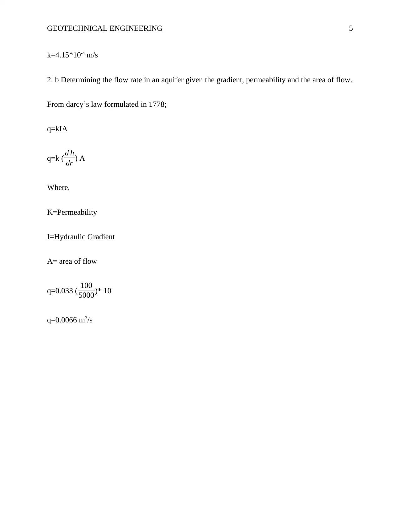
2. b Determining the flow rate in an aquifer given the gradient, permeability and the area of flow.
From darcy’s law formulated in 1778;
q=kIA
q=k ( d h
dr ) A
Where,
K=Permeability
I=Hydraulic Gradient
A= area of flow
q=0.033 ( 100
5000)* 10
q=0.0066 m3/s
k=4.15*10-4 m/s
2. b Determining the flow rate in an aquifer given the gradient, permeability and the area of flow.
From darcy’s law formulated in 1778;
q=kIA
q=k ( d h
dr ) A
Where,
K=Permeability
I=Hydraulic Gradient
A= area of flow
q=0.033 ( 100
5000)* 10
q=0.0066 m3/s
GEOTECHNICAL ENGINEERING 6
References
Craig, R. F. (2013). Soil mechanics. Springer.
Murthy, V. N. S. (2002). Geotechnical engineering: principles and practices of soil mechanics
and foundation engineering. CRC press.
Smith, G. N. (1982). Elements of soil mechanics for civil and mining engineers.
References
Craig, R. F. (2013). Soil mechanics. Springer.
Murthy, V. N. S. (2002). Geotechnical engineering: principles and practices of soil mechanics
and foundation engineering. CRC press.
Smith, G. N. (1982). Elements of soil mechanics for civil and mining engineers.
1 out of 6
Your All-in-One AI-Powered Toolkit for Academic Success.
+13062052269
info@desklib.com
Available 24*7 on WhatsApp / Email
Unlock your academic potential
© 2024 | Zucol Services PVT LTD | All rights reserved.