Understanding Gigabit Passive Optical Network (GPON)
VerifiedAdded on 2023/04/26
|60
|17435
|475
AI Summary
Gigabit Passive Optical Network (GPON) is a standard for passive optical networks (PON) published by the ITU-T. It is commonly used to implement the last kilometer of Fibre To The Premises (FTTP) services. GPON is a point-to-multipoint access network that uses passive splitters in the fiber distribution network, enabling one single feeding fiber from the provider to serve multiple homes and small businesses¹. GPON provides a solution that minimizes the physical footprint, increases distance and bandwidth, reduces latency, and improves physical and network security⁴. It also adheres to green and sustainability initiatives and reduces costs for moves, adds, and changes⁴.
Contribute Materials
Your contribution can guide someone’s learning journey. Share your
documents today.
Gigabit Passive Optical Network (GPON)
Student’s name,
Student ID,
Course
Project supervisor.
Student’s name,
Student ID,
Course
Project supervisor.
Secure Best Marks with AI Grader
Need help grading? Try our AI Grader for instant feedback on your assignments.
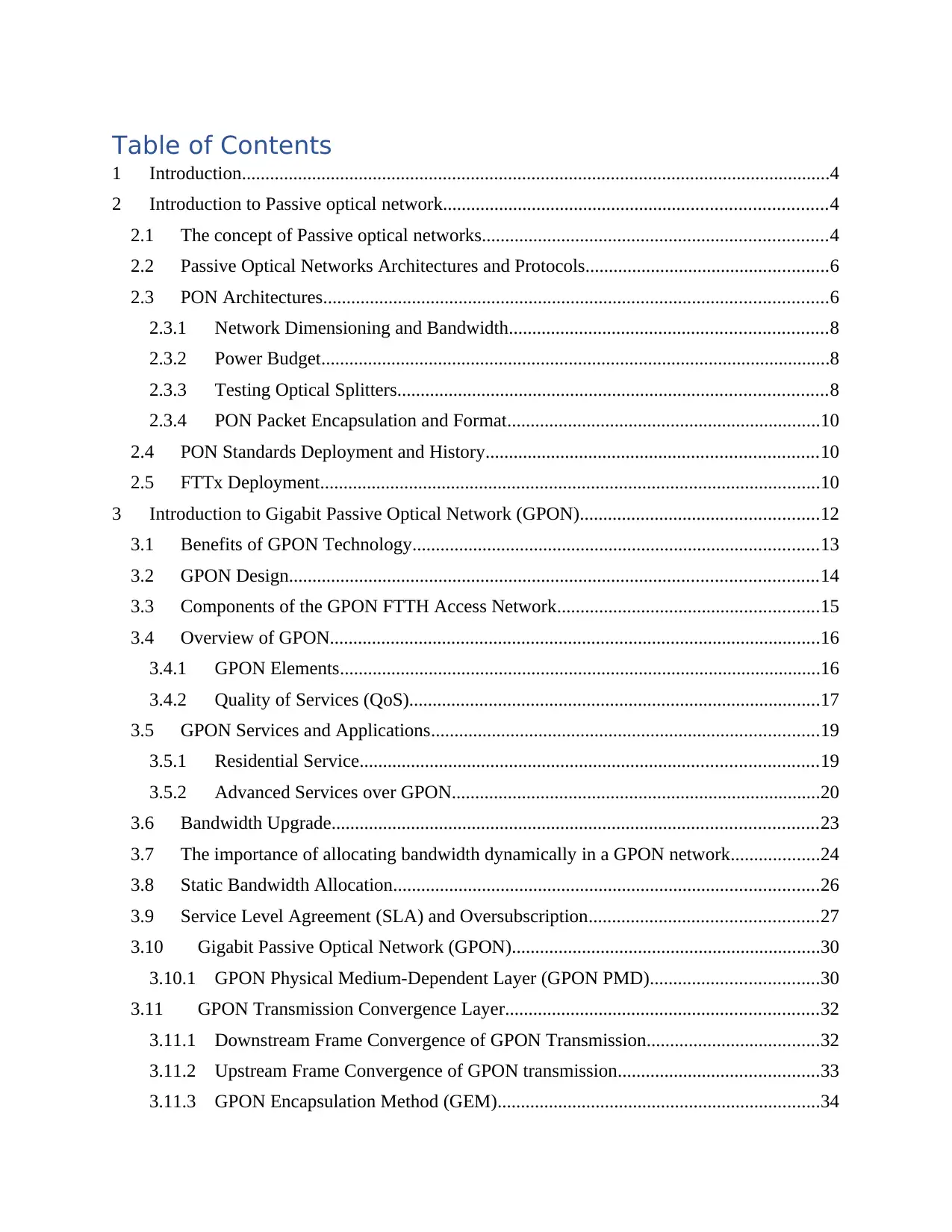
Table of Contents
1 Introduction..............................................................................................................................4
2 Introduction to Passive optical network..................................................................................4
2.1 The concept of Passive optical networks..........................................................................4
2.2 Passive Optical Networks Architectures and Protocols....................................................6
2.3 PON Architectures............................................................................................................6
2.3.1 Network Dimensioning and Bandwidth....................................................................8
2.3.2 Power Budget.............................................................................................................8
2.3.3 Testing Optical Splitters............................................................................................8
2.3.4 PON Packet Encapsulation and Format...................................................................10
2.4 PON Standards Deployment and History.......................................................................10
2.5 FTTx Deployment...........................................................................................................10
3 Introduction to Gigabit Passive Optical Network (GPON)...................................................12
3.1 Benefits of GPON Technology.......................................................................................13
3.2 GPON Design.................................................................................................................14
3.3 Components of the GPON FTTH Access Network........................................................15
3.4 Overview of GPON.........................................................................................................16
3.4.1 GPON Elements.......................................................................................................16
3.4.2 Quality of Services (QoS)........................................................................................17
3.5 GPON Services and Applications...................................................................................19
3.5.1 Residential Service..................................................................................................19
3.5.2 Advanced Services over GPON...............................................................................20
3.6 Bandwidth Upgrade........................................................................................................23
3.7 The importance of allocating bandwidth dynamically in a GPON network...................24
3.8 Static Bandwidth Allocation...........................................................................................26
3.9 Service Level Agreement (SLA) and Oversubscription.................................................27
3.10 Gigabit Passive Optical Network (GPON)..................................................................30
3.10.1 GPON Physical Medium-Dependent Layer (GPON PMD)....................................30
3.11 GPON Transmission Convergence Layer...................................................................32
3.11.1 Downstream Frame Convergence of GPON Transmission.....................................32
3.11.2 Upstream Frame Convergence of GPON transmission...........................................33
3.11.3 GPON Encapsulation Method (GEM).....................................................................34
3.11.4 GPON Downstream Encryption Method.................................................................36
3.12 Ethernet PON..............................................................................................................36
3.12.1 EPON Architecture..................................................................................................37
3.12.2 EPON Point-to-Multipoint MAC Control...............................................................40
4 PON Deployment challenges in the Next-Gen......................................................................42
4.1 Evolving Standards.........................................................................................................42
4.2 New Challenges..............................................................................................................44
4.3 The Next-generation PON Evolution Trend Discussion.................................................46
5 Conclusion.............................................................................................................................50
6 References List......................................................................................................................53
7 Appendix A: Project Schedule...............................................................................................56
8 Appendix B: Gantt Chart.......................................................................................................57
1 Introduction
Gigabit Passive Optical Networks (GPON) is a technology which has been adopted in
networking with the aim of offering significant cost reduction in network operations (Kumar,
2014). Nevertheless, large scale GPON needs a massive investment in infrastructure and
equipment. Before deploying a large scale GPON it is important to acquire smaller GPON
systems and test them to determine its suitability. This study will focus on the concept of passive
optical networks and their typical architectures, typical services and the operation principle of a
GPON, calculation of splitting power loss of optical power splitters, and analysis of the optical
power budget of a GPON.
2 Introduction to Passive optical network
Passive optical network technologies such as GPON and Ethernet PON are currently the
most used access network technologies. PON is made up of a passive optical splitter, central
optical line terminal (OLT), and a single optical network unit terminal at the client premises
connected in a tree topology (Kazovsky, 2011). In the past, PONs used TDM- time division
multiplexing for medium sharing in the case of point to multipoint connections. The OLT
broadcasts frames towards the ONUs, however, in the upstream in order to avoid collisions an
arbitration mechanism is required when ONUs is sending frames to the OLT (Hood and Trojer,
2012).
2.1 The concept of Passive optical networks
An optical network is a kind of a network that has both passive and active elements.
Active elements are in switches, repeaters, in central office, at customer residence among other
locations. However, this section will focus on the concept of passive optical networks which has
no active elements between the customer and the central office (Zhang, 2010). Additionally,
passive devices require no power supply and their main purpose is to direct the traffic signals in
specific optical wavelengths. Services such as data, video, and voice can be implemented easily
using varying wavelengths. One equipment that is mostly used is the GPON equipment. Passive
optical networks do not contain any active optical elements along the network path. The figure
Secure Best Marks with AI Grader
Need help grading? Try our AI Grader for instant feedback on your assignments.
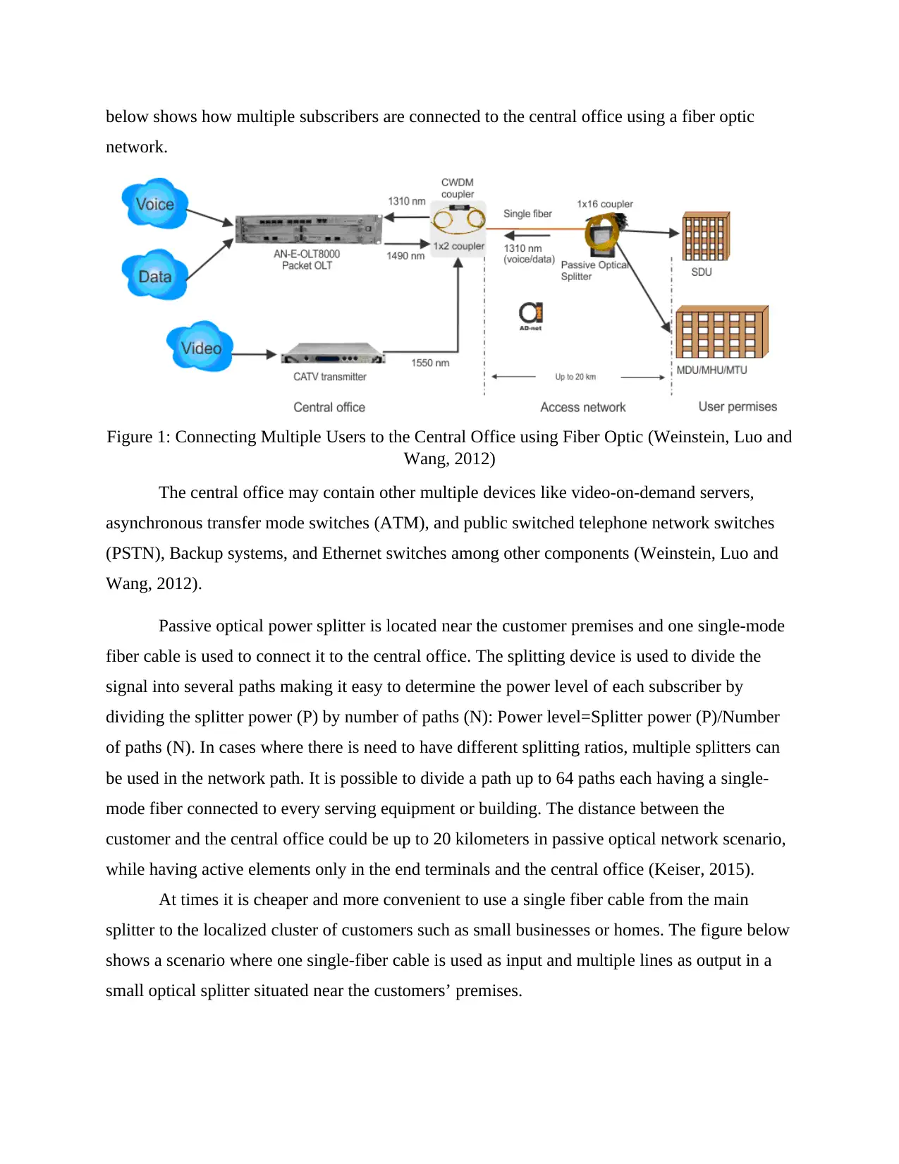
below shows how multiple subscribers are connected to the central office using a fiber optic
network.
Figure 1: Connecting Multiple Users to the Central Office using Fiber Optic (Weinstein, Luo and
Wang, 2012)
The central office may contain other multiple devices like video-on-demand servers,
asynchronous transfer mode switches (ATM), and public switched telephone network switches
(PSTN), Backup systems, and Ethernet switches among other components (Weinstein, Luo and
Wang, 2012).
Passive optical power splitter is located near the customer premises and one single-mode
fiber cable is used to connect it to the central office. The splitting device is used to divide the
signal into several paths making it easy to determine the power level of each subscriber by
dividing the splitter power (P) by number of paths (N): Power level=Splitter power (P)/Number
of paths (N). In cases where there is need to have different splitting ratios, multiple splitters can
be used in the network path. It is possible to divide a path up to 64 paths each having a single-
mode fiber connected to every serving equipment or building. The distance between the
customer and the central office could be up to 20 kilometers in passive optical network scenario,
while having active elements only in the end terminals and the central office (Keiser, 2015).
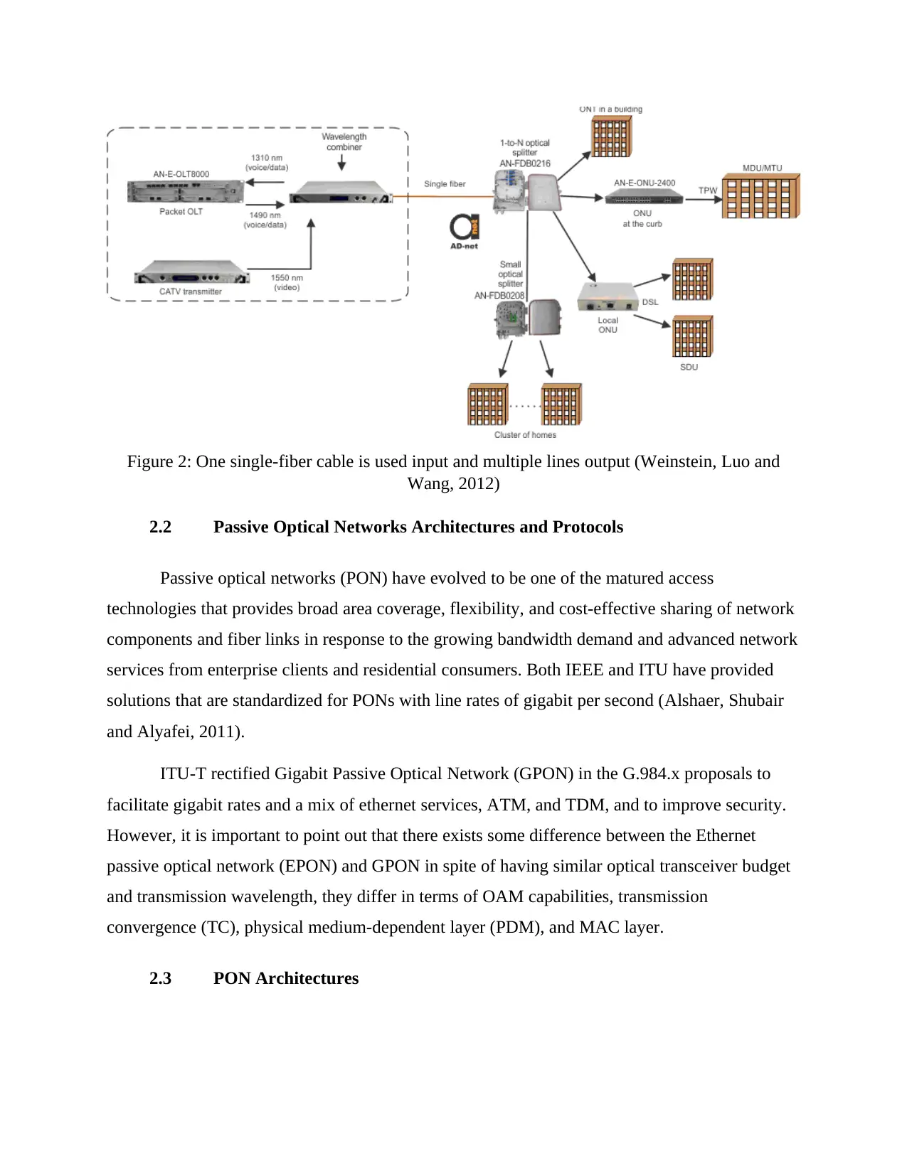
At times it is cheaper and more convenient to use a single fiber cable from the main
splitter to the localized cluster of customers such as small businesses or homes. The figure below
shows a scenario where one single-fiber cable is used as input and multiple lines as output in a
small optical splitter situated near the customers’ premises.
Figure 2: One single-fiber cable is used input and multiple lines output (Weinstein, Luo and
Wang, 2012)
2.2 Passive Optical Networks Architectures and Protocols
Passive optical networks (PON) have evolved to be one of the matured access
technologies that provides broad area coverage, flexibility, and cost-effective sharing of network
components and fiber links in response to the growing bandwidth demand and advanced network
services from enterprise clients and residential consumers. Both IEEE and ITU have provided
solutions that are standardized for PONs with line rates of gigabit per second (Alshaer, Shubair
and Alyafei, 2011).
ITU-T rectified Gigabit Passive Optical Network (GPON) in the G.984.x proposals to
facilitate gigabit rates and a mix of ethernet services, ATM, and TDM, and to improve security.
However, it is important to point out that there exists some difference between the Ethernet
passive optical network (EPON) and GPON in spite of having similar optical transceiver budget
and transmission wavelength, they differ in terms of OAM capabilities, transmission
convergence (TC), physical medium-dependent layer (PDM), and MAC layer.
2.3 PON Architectures
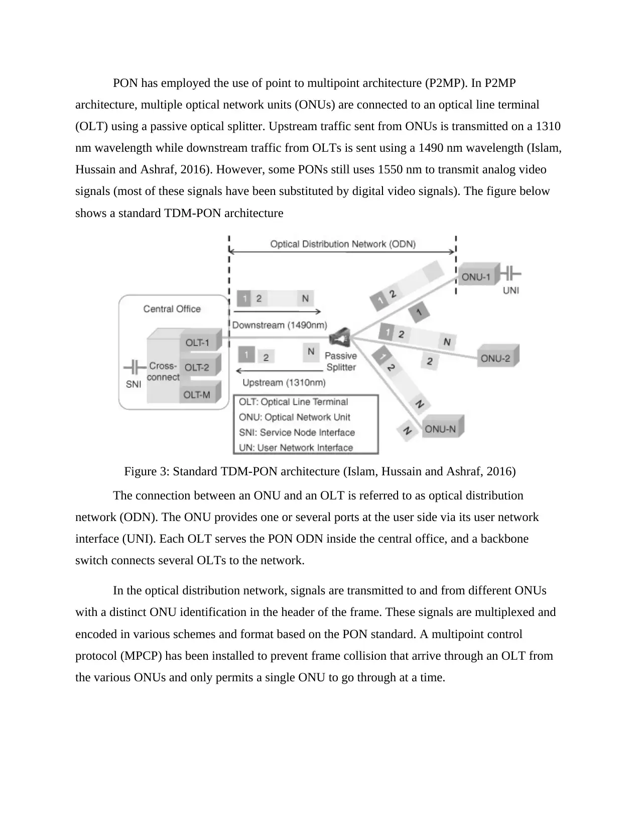
PON has employed the use of point to multipoint architecture (P2MP). In P2MP
architecture, multiple optical network units (ONUs) are connected to an optical line terminal
(OLT) using a passive optical splitter. Upstream traffic sent from ONUs is transmitted on a 1310
nm wavelength while downstream traffic from OLTs is sent using a 1490 nm wavelength (Islam,
Hussain and Ashraf, 2016). However, some PONs still uses 1550 nm to transmit analog video
signals (most of these signals have been substituted by digital video signals). The figure below
shows a standard TDM-PON architecture
Figure 3: Standard TDM-PON architecture (Islam, Hussain and Ashraf, 2016)
The connection between an ONU and an OLT is referred to as optical distribution
network (ODN). The ONU provides one or several ports at the user side via its user network
interface (UNI). Each OLT serves the PON ODN inside the central office, and a backbone
switch connects several OLTs to the network.
In the optical distribution network, signals are transmitted to and from different ONUs
with a distinct ONU identification in the header of the frame. These signals are multiplexed and
encoded in various schemes and format based on the PON standard. A multipoint control
protocol (MPCP) has been installed to prevent frame collision that arrive through an OLT from
the various ONUs and only permits a single ONU to go through at a time.
Paraphrase This Document
Need a fresh take? Get an instant paraphrase of this document with our AI Paraphraser
2.3.1 Network Dimensioning and Bandwidth
PON systems are limited both in bandwidth and range as it supports between 32 to 64
splits and covers a distance of up to 20km only (Preet and Dewra, 2015). PON system dimension
is restricted partly by power budget. Upstream receiver dynamic range and fiber dispersion
further restricts PON system dimension in realistic deployment. Both GPON and EPON, in terms
of bandwidth, supports Gb/s rates of transmission but vary in actual transmission rates. In order
to achieve 100% bandwidth efficiency, GPON uses no return to zero (NRZ) code but at the
expense of purchasing expensive transceivers. Due to this, GPON is capable of 1.244 Gb/s rate
upstream (OC-24) and 2.488 Gb/s rate downstream (OC-48) (Preet and Dewra, 2015).
2.3.2 Power Budget
It is possible to compute fiber reach L(km) and limiting split ratio N provide with the
power budget as Pbudget = Pt - Ps(dB), system margin Ms(dB), and fiber loss coefficient αf(dB/km)
(Li and Zhang, 2010). the type of transceiver used in the systems can be used to determine the
power budget by calculating the difference between receiver sensitivity Ps and transmitter launch
power Pt (Skubic and Hood, 2011). Both GPON and EPON support the same dimensioning
because they depend on virtually similar underlying physical system (Li and Zhang, 2010).
Additionally, GPON supports the same optical transceivers in class B (Pbudget=25; dB) and class
A (Pbudget=20; dB) (Islam, Hussain and Ashraf, 2016). When class A transceivers are used, it
means that there is need to employ PIN laser/FP receiver at the ONU and DFB laser/APD
receiver at the OLT. For class C transceivers both ONU and OLT uses DFB laser/APD receivers.
To determine the maximum fiber reach and split of a PON system, the equation below should be
used (Yin, Li and Zhang, 2011).
(1)
(2)
Figure 4: Optical Power Budget and Margin Calculation (Yin, Li and Zhang, 2011).
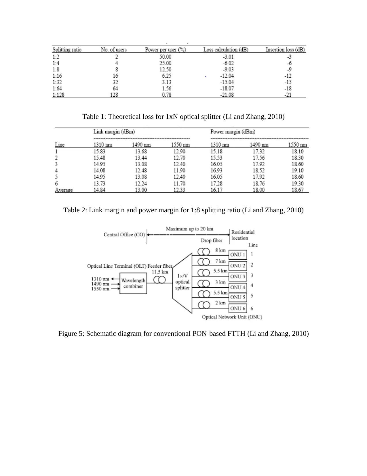
Table 1: Theoretical loss for 1xN optical splitter (Li and Zhang, 2010)
Table 2: Link margin and power margin for 1:8 splitting ratio (Li and Zhang, 2010)
Figure 5: Schematic diagram for conventional PON-based FTTH (Li and Zhang, 2010)
Table 2: Link margin and power margin for 1:8 splitting ratio (Li and Zhang, 2010)
Figure 5: Schematic diagram for conventional PON-based FTTH (Li and Zhang, 2010)
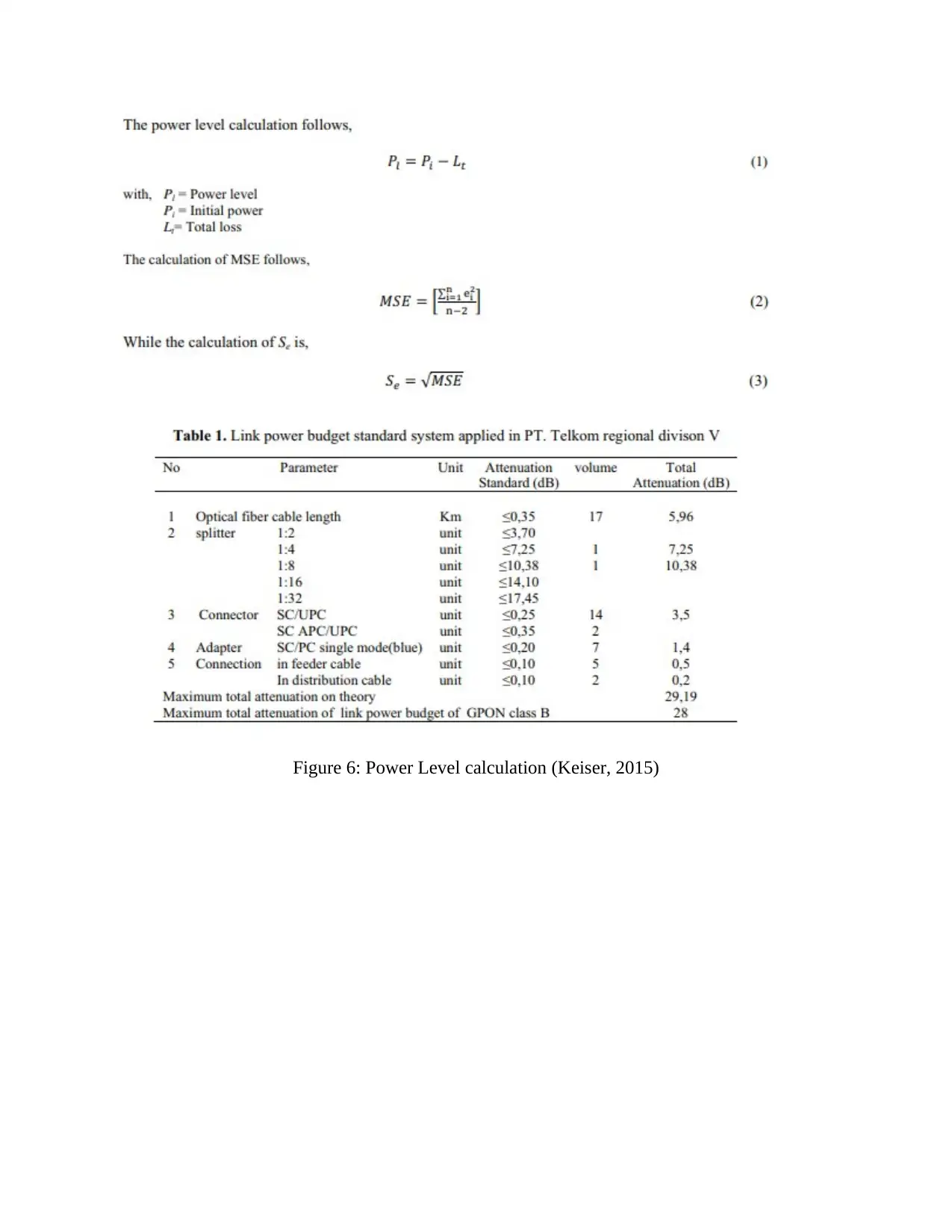
Figure 6: Power Level calculation (Keiser, 2015)
Secure Best Marks with AI Grader
Need help grading? Try our AI Grader for instant feedback on your assignments.
Figure 7: Average optical power budget for each optical line in conventional PON-based FTTH
(Yin, Li and Zhang, 2011).
Figure 8: Average optical power budget for each optical line in proposed PON-based i-FTTH
(Yin, Li and Zhang, 2011).
2.3.3 Testing Optical Splitters
Optical splitters are normally used to distribute fiber to business enterprises and
residential homes in passive optical networks. This section will describe optical splitter loss
testing using light source and optical power meter. Some of the examples of optical splitters
include planar light wave circuit (PLC) splitters and fused biconical taper (FBT) couplers, which
are commonly used to split fiber optic cables by a specific ratio into multiple parts. For instance,
(Yin, Li and Zhang, 2011).
Figure 8: Average optical power budget for each optical line in proposed PON-based i-FTTH
(Yin, Li and Zhang, 2011).
2.3.3 Testing Optical Splitters
Optical splitters are normally used to distribute fiber to business enterprises and
residential homes in passive optical networks. This section will describe optical splitter loss
testing using light source and optical power meter. Some of the examples of optical splitters
include planar light wave circuit (PLC) splitters and fused biconical taper (FBT) couplers, which
are commonly used to split fiber optic cables by a specific ratio into multiple parts. For instance,
a splitter with 1x4 ratio means that it has 4 outputs and one input (Walid and Chen, 2010).
Similarly, there are 1x2, 1x8 splitters, and so on.
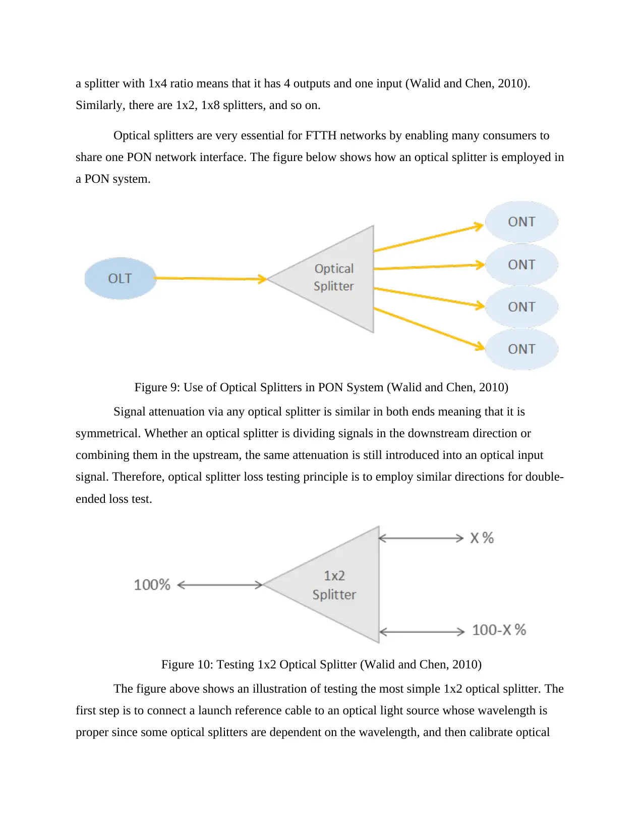
Optical splitters are very essential for FTTH networks by enabling many consumers to
share one PON network interface. The figure below shows how an optical splitter is employed in
a PON system.
Figure 9: Use of Optical Splitters in PON System (Walid and Chen, 2010)
Signal attenuation via any optical splitter is similar in both ends meaning that it is
symmetrical. Whether an optical splitter is dividing signals in the downstream direction or
combining them in the upstream, the same attenuation is still introduced into an optical input
signal. Therefore, optical splitter loss testing principle is to employ similar directions for double-
ended loss test.
Figure 10: Testing 1x2 Optical Splitter (Walid and Chen, 2010)
The figure above shows an illustration of testing the most simple 1x2 optical splitter. The
first step is to connect a launch reference cable to an optical light source whose wavelength is
proper since some optical splitters are dependent on the wavelength, and then calibrate optical
power meter with the launch reference cable to set the 0db reference (Walid and Chen, 2010).
Secondly, attach the splitter to the light source and connect optical power meter and output to the
receive launch reference cable, and measure the loss. Move the receive launch cable to a
different port in order to test the loss to the second por and read the loss from the meter.
2.3.4 PON Packet Encapsulation and Format
What distinguishes GPONs and EPONs is the type of frame or packet transmission they
support. Currently, Ethernet forms the majority of the internet traffic, also is PON traffic. People
have often had a misunderstanding that GPON cannot efficiently support ethernet traffic. This is
false as GPON have inherited some parts of ATM format and networking from its predecessor
BPON and APON. In addition to packet reassembly and packet fragmentation, GPON have
employed GPON Encapsulation method (GEM) to support any type of packet or frame. From
this, we can conclude that EPON is less flexible GPON because GPON has the capabilities to
support TDM, Ethernet, and ATM services. Additionally, it has the capacity to support packet
reassembly and fragmentation which is not present in Ethernet-based MAC.
2.4 PON Standards Deployment and History
The table below gives the difference between standardized EPON, GPON, and BPON
parameters.
Figure 11: Comparison between EPON, GPON, BPON (Source: Preet and Dewra, 2015)
2.5 FTTx Deployment
Paraphrase This Document
Need a fresh take? Get an instant paraphrase of this document with our AI Paraphraser
Optical access networks come in different types: passive or active point to multipoint
(P2MP) and point to point (P2P). FTTx is a popular term that is used to refer to fiber to x, where
x represents any deployment scenario. The figure below represents the most popular reference
FTTx types of deployment. Fiber to the building (FTTB), fiber to the cabinet (FTTC), and fiber
to the home (FTTH) shown in the figure represents the various levels of fiber penetration. FTTB
and FTTC represents a deployment scenario where the consumers are connected via hybrid use
of radio, twisted pair, or coaxial cable.
The main difference between FTTB and FTTC can be noted by the level of fiber
penetration where FTTB place ONU inside a multi-dwelling unit (MDu) and FTTC connects
generally to an active cabinet that is remote. Fiber to the premises (FTTP) and fiber to the
business (FTTB) are the two types of fiber to the home (FTTH) deployments and are used to
indicate further connections to the premises or residential customers. Fiber to the curb (FTTC)
can also be used to refer to FTTB. The figure below shows the architecture of an optical access
network
Figure 12: Architecture for an optical access network. (Source: Islam, Hussain and Ashraf, 2016)
Many users of FTTx term does not necessary give specific physical configuration
although evert FTTx deployment type have different levels of fiber penetration understanding.
Mostly users use FTTx to refers to their expectations concerning investment payback periods,
service offerings, customer devices, and service-level agreement (SLA)
3 Introduction to Gigabit Passive Optical Network (GPON)
A Gigabit Passive Optical Network (GPON) system is a point to multipoint, bidirectional
network architecture used for deploying optical access lines between customers’ sites and the
central office of the carrier (Milanovic, 2014). Today, GPON is widely applied in FTTx (fiber to
the home) networks. FTTx networks are being applied in pot to multipoint (P2MP) and point to
point (P2P) time multiplexed PON (passive optical network) architecture (Sitohang and
Setiawan, 2018). GPON is a fiber access technology that is widely used across the world to
deliver high-speed data, video, and voice services to business and residential clients. GPON
operate on P2MP access mechanism allowing one fiber feed form the carrier’s central office to
serve many small businesses and homes because it has passive splitters in the fiber distribution
network.
GPON has an upstream capacity of 1.244Gbp/s and a downstream capacity of
2.488Gbp/s which share among the end users (Cale, Salihovic and Ivekovic, 2011). To maintain
privacy and security of the users’ data and information, encryption is used to ensure that no
unauthorized person gains access to the data being transmitted. GPON is one of the lowest,
longest life, and high-speed network infrastructure available currently further argues Cale,
Salihovic, and Ivekovic. Additionally, it offers genuine and flexible technology to support any
future modifications or upgrade (future-proof access network).
According to Hood and Trojer (2012), GPON is transforming several government and
business agencies because of the green, power saving, and high bandwidth technology used.
GPON uses passive splitters to enable the use of one fiber feed to perform the functions that
could have been otherwise done by several fibers allowing the users to use one fiber data
network to consolidate several services. One major benefit associated with GPON is its ability to
scale without having to re-cable the network afresh (Brenkosh, 2015). It allows configuration of
several users with many OLT chassis in systems. Additionally, GPON allows migration in the
future without having to replace the passive infrastructure.
The result of a GPON network is flexible, future-proofed, high capacity optical fiber
network for all services depending on IP including security systems, Video on demand, access
control and door entry, POS terminals, VoIP telephony, high/ ultra-high definition IPTV, high
speed internet, interactive signage PIDS, Wi-Fi access nodes, and automated minibar systems
(Hood and Trojer, 2012).
3.1 Benefits of GPON Technology
As compared to active Ethernet, Brenkosh (2015) claims that GPON networks offers
numerous advantages both to the providers and the consumers. Some of the GPON benefits that
Brenkosh identifies in his article include:
GPON networks has the ability to cover a greater range. A single-mode fiber can transmit
packets for up to 20km like the one used in GPON systems as compared to copper cable which is
only limited to 100m. Secondly, it offers high speed connections because of the high
performance offered by fiber optics which has a bandwidth of up to 25Gbits/s the hub and
5Gbits/s downstream (ctscabling.com, 2018). If the business is growing, it won’t experience
challenges if it wants to scale up to 40Gbits/s without having to upgrade the cables.
GPON technology has the advantage of saving the space used. GPON fiber can be
described to be just a small percentage of the traditional copper cables, that is, less space will be
needed for laying the cables through the organization. Additionally, GPON technology does not
require many signal boosting equipment because of the extended signal reach, therefore, the
company will only require less server rooms to maintain the business IT infrastructure
(Cochennec, 2012). Moreover, GPON fiber optic cables are less expensive as compared to
copper-based LAN cables. This will result in to long term savings by doing away with wiring
closets required by the copper cables. Nokia Bel Labs conducted a research on copper Ethernet
LAN vs. PON cables and concluded that the business will enjoy up to sixty percent decrease
after five years in total cost of ownership further explains Cochennec.
GPON technology also offers flexible coverage capacity and one can achieve full
coverage for data, voice, Wi-Fi backhaul, and other functions required from a network to carry
out business. Finally, GPON technology is environmentally friendly because it powerful but
efficient. It does not require any specific temperature requirements meaning that the business
will not need to set up air conditioning system resulting to less energy consumption.
Secure Best Marks with AI Grader
Need help grading? Try our AI Grader for instant feedback on your assignments.
This above network setup cost much less as compared to having a long fiber link
connecting each user from the main splitter. In the above diagram, optical distribution network
(ODN) represents a collection of couplers, passive equipment, and fibers that are installed
between ONUs and ONTs and OLT. Feeder cable connects the optical splitter to the central
office which can divide the signal to 32 subscribers. The distance between the central office and
the optical splitter is 10km while that between the subscribers is 1km as described in the figure
above.
3.2 GPON Design
There has been a lot of growth in the demand for the high-speed internet whose primary
objective is to give new access to all the technologies which in turn will enable one to experience
the true broadband. This may lead to an operator of telecommunication to find himself
considering the high volume roll out of the optical fibers which are on the basis of the access
networks in place. In this case, they will need to renew the existing access networks and thus this
becomes a bottleneck when it comes to bandwidth (Kadhim and Hussain, 2013). Kadhim and
Hussain further mentions that most providers of telecommunication services have been
withdrawing from the copper network and thus giving the optical fiber network way to show
their benefits. The optical fiber has been able to get closer to the subscribers and thus allowing
the connections to be much faster. FTTH (Fiber-To-The-Home) has appeared to be one of the
most suitable choices when it comes to choosing long-term objectives. When our clients are fully
served by the optical fibers then it will be very easy to increase the bandwidth in the coming
future.
FTTH has acted as the proof solution that provides broadband services such as the
gaming online, video-on-demand, VoIP as well as the HDTV. FTTH networks are known to
technically exploit a low attenuation of about 0.2 to about 0.6 dB/km and thus having a high
bandwidth of about more than 30,000 GHz of the single mode optical fibers, thus it provides as
many times of the bandwidth than all the currently available and existing broadband technologies
(Kadhim and Hussain, 2013). In addition, FTTH has the capability to provide all their
communication services which are the voice, video as well as the data from the specific network
platforms.
There are various Time Division Multiplexing including TDM PON technologies which
are standardized for FTTH deployments. The main limitation is that TDM PON is not possible
for more than one operator to be able to share the same fiber physically (Islam, Hussain and
Ashraf, 2016). The multiple-fiber deployment has been necessary to physically be able to share
to access the network. WDM PON which is the Wavelength Division Multiplexing Passive
Optical Network is known to be the next generation in the access networks development. These
two specific flavors are always studied by study group 15 which is one of the international
Telecommunication Union-Telecommunication Standardization Sector. In this case, the first to
be considered is time and wavelength division multiplexing PON which in this case, it is known
for having a transmission of about 4 to about 16 wavelengths on the same specific fiber that can
support very high number of users per any given fiber using very high transmission rates or in
some case they may be more important in allowing that there is more than one operator in
sharing such in the same fiber. In this case the operators will in turn be able to work at different
wavelengths. The second one has an arrayed waveguide grating (AWG) on the basis of the
WDM-PON which has an aim of offering provisions to each user with a dedicated wavelength
and which is similar to p2p and thus is able to support about 2.25 Gbps downstream and
1.25Gbps upstream transmission capacity.
3.3 Components of the GPON FTTH Access Network
A Passive optical network is simply a point to multiple point, shared optical fiber to the
network architecture premises where all the unpowered optical splitters are used to enable the
single optical fiber in serving the multi-premises which may be typically be 64 to about 128 (Li
and Zhang, 2010). PON are in most cases passive in the essence that they always employ a
passiveness as shown in a simple optical splitter and thus acting as the combiner for the data
transport further mentions Li and Zhang. PON in most cases takes advantage of the WDM in
that, by using one wavelength in down streaming the traffic and another for upstreaming the
traffic on a single Non-Zero dispersion in a shifted fiber.
1. Optical Line Terminal (OLT)
This is simply the main element of the specific network which in most cases is placed in
the local exchange and thus acting as the engine that drives the FTTH systems. The function
which is much significant is that OLT can perform scheduling of the traffic, controlling of the
buffer and allocating the bandwidth. In most cases, OLT is used in operating the use of
redundant DC power of about (-48V DC) and in it always have a minimum of one-line card for
any incoming internet, at least one system card for the on-board configuration and one to many
Cards of GPON (Brenkosh, 2015). Each and every GPON card always contains some GPON
ports.
2. Optical splitters.
This component is known for splitting the power of a particular signal from each and
every link entering the splitter and thus it can also be split in to more fiber links leaving the
splitter. There is usually 3 or even more levels of the fibers corresponding to either two or even
more splitter levels. This in most cases helps in sharing between each fiber as it is being used by
different users. Notably, due to splitting of the power, FTTH signals may attenuate though the
structure may remain the same all the time. Passive optical splitter in most cases they may need
to have such characteristics (Kadhim and Hussain, 2013).
broad operating wavelength range
low insertion loss and uniformity in any conditions
minimal dimensions
high reliability
support network survivability and protection policy
3.4 Overview of GPON
What standardizes GPON technology is recommendations from ITU-T and its seven
extensions. GPON has the capability to support several services base on technologies that are
different such as asynchronous transmission mode (ATM) Ethernet, and TDM. Therefore, GPON
can be a considered a technology that suits triple-play services (Brenkosh, 2015). FTTH is one of
the most popular GPON network architecture which enables narrowband services like integrated
service digital network (ISDN) and plain old telephone service (POTS) in addition to asymmetric
and symmetric broadband services.
3.4.1 GPON Elements
GPON has five elements which are elaborated in the figure below.
Paraphrase This Document
Need a fresh take? Get an instant paraphrase of this document with our AI Paraphraser
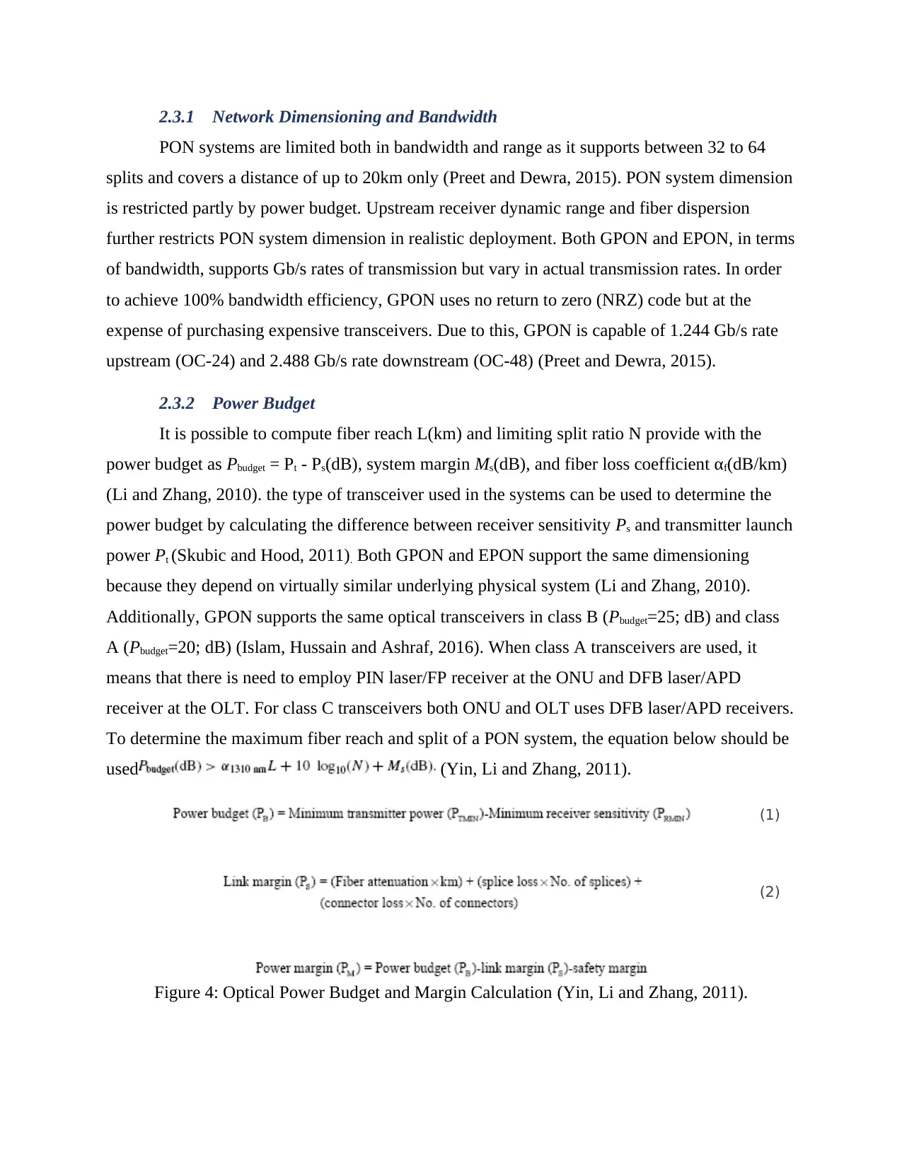
Figure 13: GPON Elements (Source: Brenkosh, 2015)
The aggregation switch (AS) is in charge of allowing traffic from the rest of the network.
Service network interface (SNI) is responsible for linking AS to the rest of the
telecommunication network. The SNI is used normally used as an ethernet link with speeds of up
to 10Gb/s links or several gigabit ethernet (GE). An internal bus is used to connect the optical
line terminal (OLT) and the AS forming an essential part of the backplane (common chassis).
However, this device does not make up the GPON standard.
GPON management functions regarding optical network terminals (ONTs) are supported
by the OLT through the ITU G.984 OMCI interface (compliant operation, management, and
control interface). Bandwidth allocation, buffer control, and traffic scheduling are some of the
important functions of the OLT. Some of the OLT optical characteristics include sensitivity, use
of forward error correction (FEC), bit rate, transmit power among others.
The optical distribution network (ODN) is used to transmit optical signals to the ONUs
from the OLT. GPON employs point to multi-point architecture which operates on the basis of
splitting optical signals. GPON classes A, B, BC, C, and CC are used to define the ODN. Class
BC is the most popular since it enables optical signals to be split for up to 64 users and a distance
of up to 20 km.
3.4.2 Quality of Services (QoS)
In GPON technology, provision of quality of service (QoS) is fount on the second layer
of the OSI hierarchy. It enables use of GPON in several network architectures and applications.
Primarily, this refers to users and applications who ask for a service level agreement (SLA).
Assurance of QoS is only possible if it is appropriately provided in the ONU and OLT. In order
to achieve QoS, it is important to employ the following mechanisms: control of downstream
flow, dynamic bandwidth assignment (DBA), and GPON encapsulation method (GEM) as
transport mode.
Dynamic Bandwidth Assignment (DBA): this is the method that ONUs and related
transport container (T-CONT) request upstream bandwidth dynamically. This can be achieved in
two ways: status reporting (SR) and non-status reporting (NSR) DBA. However, there are more
essential possibilities of related T-CONT from QoS point of view. It is possible to offer multiple
categories of traffic using the five different type of T-CONTs: Type 1 T-CONT is used for
bandwidth that is fixed, Type 2 and Type 3 are used for bandwidth that is guaranteed and is
majorly employed for data services and video services with higher priorities (Stepniak, 2013).
Type 4 is used for best effort, and finally Type 5 is employed in an environment with mixed
traffic.
Bandwidth allocation depends on bandwidth category. In this case, fixed bandwidth is
cyclically allocated and is recommended for static bandwidth management. Nevertheless, other
groups are dynamically allocated by the DBA function and is distributed between the different
traffic flows from every ONT and among the different ONT. DBA gives GPON two benefits:
one is effective use of bandwidth and improved quality of service.
GPON encapsulation method (GEM): GPON has two modes of transport which are
ATM and GEM. The two modes can be used to provide quality of service. However, GEM is
more preferred because of its high transmission efficiency of the various types of traffic from
packet to TDM. Additionally, GEM supports service differentiation which is a unique
mechanism that other transport modes lack. GEM cells can be variable in length unlike in ATM
transport mode that operates with fixed length cells. The maximum amount of payload supported
by GEM can vary up to 12 bits. GEM has an efficiency of 93% upstream and 94% downstream
traffic. As such, it is capable of supporting ethernet transport efficiency over a GPON. The OLT
can be linked with various traffic flows as a result of specific GEM mechanism. GEM, in other
words, can be considered as a virtual port identifier necessary for a specific GPON service. This
supports queuing of traffic from every physical port to 8 separate queues after classification of
traffic flow.
Control of Downstream Flow: GPON ITU-T recommendations has not defined this
mechanism at all, but it makes up the essential part of the system implemented. It is possible to
efficiently control upstream traffic by DBA, but there is no mechanism defined in the
downstream traffic. The mechanism ascribed to GPON give classical flow control which can be
attained by ONU or GEM.
Different User’s Profile: as described, full traffic differentiation per service or per ONU
port can be offered in the GPON. This enables creation of different profiles for the different
users for every service or physical port. As a result, it is possible for GPON to create profiles for
users that are unique for every user based on the services needed by a specific user. Allocation of
bandwidth to users is done in a PON tree based on what the user needs or has paid for. If the
bandwidth is not requested or paid for will not be divided among users in a PON tree, as such, it
will be redirected to other network services.
3.5 GPON Services and Applications
Services over GPON can be broken down into two categories: advance services (services
to multi-users and business users over a GPON port) and classical services (TV, data, and Voice)
which are majorly available for residential users (Kumar, 2014).
3.5.1 Residential Service
Phone service: this is one of the popular telecommunication services. Several protocols
can be used to provide voice service over GPON including H.248, Session Initiation Protocol
(SIP), and V.5.2. The figure below illustrates different possibilities of a phone service.
Figure 14: Different Possibilities of Phone Services (Source: Kumar, 2014)
Most of the components have the option to shift from one method to another making
GPON flexible and more reliable. OMCI defines the method for voice service provision. There
are no problems when moving from V.5.2 users to the SIP as shown in the figure above during
Secure Best Marks with AI Grader
Need help grading? Try our AI Grader for instant feedback on your assignments.
the realization of the system. It is possible to have more that two users on the same PON tree
without affecting the communication process.
Triple-Play Services: residential clients are the popular users of these services. There
exist various types of triple-play service transfer which can only be categorized into two major
types based on the type of triple-play service it offers: Standard with high-definition-TV
(HDTV) and without HDTV. Users using HDTV require more that 15 Mbps (mostly 20 Mbps)
but those who does not need HDTV can be satisfied with a bandwidth of 10 Mbps in the
downstream directions. The formulae for obtaining available bandwidth in the downstream
direction is Bwi D. BRds hdw/=Nusers per PON; where hdw represents downstream efficiency
factor, BRds represent GPON downstream rate, and Nusers per PON represent the number of
user connected per PON tree. The amount of traffic transmitted determines the efficiency factor.
Greater efficiency is implied based on long packets and traffic. It can be concluded that GPON
bandwidth is more than what a triple-play service. The extra bandwidth can be used in other
applications and services.
3.5.2 Advanced Services over GPON
This section gives a description of various tested applications and services to more that
one user per ONU and to business users. It should be stressed that service realization over GPON
is not common among the traditional business users because it could highlight their traffic
received on a single PON tree by all users. As such, applications associated with transmission of
confidential data like indoor communications and bank transactions are not tested, although these
services can be implemented with high reliability.
Users from the public sector including government institutions, health centers, schools,
etc. and small users were tested under business. Services that are normally used by these
categories of users can access voice services such as IP Centrex or TDM and internet services.
More than One User/ONU: every port can serve different users if it can get a bandwidth
with different SLA on a GPON ONT. A mini switch is used in scenarios where users need more
than one service. The ONU and the mini switch does not have to come from the same
manufacturer (Gong et al., 2015). The figure below gives a visual representation of how to use
ONU to provide the various services, and in this scenario 4 users have been used.
`
Figure 15: Multiuser per one port (Source: Gong et al., 2015)
The ONU is linked to a GPON OLT with optical fiber while the home networks are
linked through mini routers using unshielded twisted pair (UTP) cables to a single ONU.
Fiber to the business/home (FTTB/H) application: implementing FTTH architecture
using GPON offers an excellent infrastructure for shifting from optical signals to electrical
signals at the end points to transmit signals via existing copper cable installations within the
residential or business buildings to the final end user. It is possible to achieve this through GPON
by adopting either of the two scenarios: one is ensuring that every user on the FTTH/B is given
the same rights as those over the ONU and two is using uplink for mini DSLAM. The second
scenario, as explained in the previous sections, is that fiber to the business connection is
achieved through an ONU through an ethernet link with a transmission capacity of up to 1 Gb/s.
Quality of service is offered to every service by employing one service per VLAN. In essence,
every service with a unique VLAN is awarded priority rights. In the first case, every user is
given their own bandwidth meaning that quality of service can be attained for every individual
service and individual user. The users are given the same possibilities and rights regardless of
whether he/she is connected to the FTTN or ONU. The FTTB unit can be a layer 2 ethernet
switch; this setting is referred to as a mini DSLAM or FTTBCLAN.
Using GPON for Global system for mobile communications base station for 2nd and 3rd
generation. A passive optical network is a system that is strictly controlled in terms of
synchronization. Every ONU is synchronized to the OLT (in this case ONU is the slave and OLT
is the master). 1011 level of accuracy of synchronization is possible between ONU and OLT
which relates to the stratum 1 synchronization level that is defined by American National
Standard Institute (ANSI). A system that is properly calibrated at this minimum accuracy will
offer bit-stream timing that will not experience synchronization slips more than once every 5
months. Physical synchronization field (Psync) is used to accomplish synchronization in GPON.
Psync is a section of physical control block downstream (PCBd) and is a 32-bit sequence. Psync
takes place at the start of every GPON frame as shown in the figure below.
Figure 16: GPON Frame Format (Source: Ignatov, 2016)
GPON downstream frame time length is 125 ms, which tallies with E1 signal frame
length and forms the basis for TDM communication clock (Ignatov, 2016). A GPON with the
motioned features is recommended for applications that request packet traffic and TDM
transmission simultaneously.
A GPON with the described possibilities regarding synchronization is ideal for
applications that request simultaneous transmission of TDM and packet traffic. An example of
such application is GSM core traffic transmission to base station second and third Generation
(BS 2/3 G). in this scenario, BS 2G demands TDM traffic with at least 0.05 ppm (parts per
million) frequency accuracy.
BS 3G, at the same time, requests data traffic at 21 Mb/s or 42 Mb/s download bit rate.
The figure below shows how a GPON was tested for this application
Paraphrase This Document
Need a fresh take? Get an instant paraphrase of this document with our AI Paraphraser
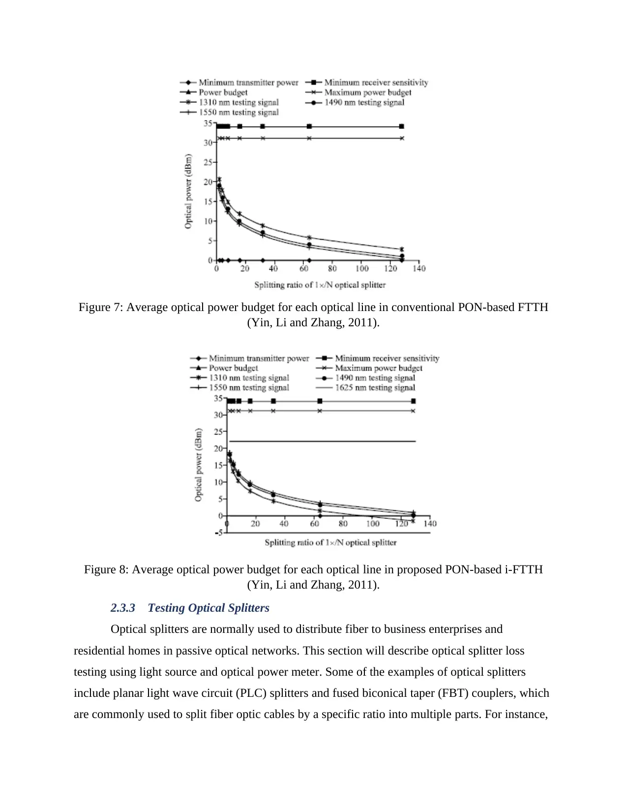
Figure 17: Connection of GSM BS 2/3 G over GPON (Source: Ignatov, 2016)
A bit error rate tester (BERT), in this test, was connected to the synchronous digital
hierarchy network (SDH) on the GSM exchange side. On the other side of the SDH network is a
media converter which converts E1 signal to IP traffic. The MC can be connected to a GPON AS
over a transport network or can be connected directly. In the above scenario, both methods were
tested, but since the OLT and the MC were in the same place, direct connection was selected to
avoid unnecessary hops. MC synchronization clock was read from E1 that was used in V.5.2.
phone service while for the OLT it was read from network synchronization as a 2-MHz signal.
The used ONT at the side of the BS contained one GE, for fast ethernet ports, two SIP phones,
and four E1 ports. The test took twenty days to complete. During this period, no synchronization
slips and no bit errors were identified. From the above figure, we can see that the configuration
did not have any optical splitters in the outside plant that is made up of fiber optic cables. The
optical splitter is placed inside the Optical distribution frame (ODF).
3.6 Bandwidth Upgrade
As mentioned in the previous section, GPON total bandwidth is more than enough for the
classical services, however, there are questions as to whether this bandwidth will support the
future needs for the users of a network. There are two concerns regarding bandwidth upgrade.
First, it is not necessary to use full capacity in relation to the number of users on a single PON
tree. It has been reported that some telecom companies are using Pusers per PON D 22 meaning
that the bandwidth available per user is 100 Mb/s. secondly, is migrating from GPON to next
generation passive optical network (NGPON). The discussion that revolve around NGPON was
concluded and a new standard was produced called 10-gigabit-capable PON otherwise known as
XGPON that ITU-T Recommendations G.987.1, 2, and 3 standardized in 2010. NGPON has two
configurations 2.5 Gb/s upstream and 10 Gb/s downstream. GPON development path should
have the following: for a GPON 1.2 Gb/s upstream and 2.5 Gb/s downstream, for NGPON 10
Gb/s both upstream and downstream, and for an XGPON 2.5 Gb/s upstream and 10 Gb/s
downstream. The recommendation is to take care of the migration path in addition to bandwidth
upgrade. This means that the migration path should be smooth meaning the if a user request
more bandwidth, the other users on the same PON tree should not be affected. Coexistence of
NGPON and GPON resolves this migration path on the same PON tree as shown in the figure
below. The figure below shows an upgrade from GPON to NGPON.
Figure 18: GPON to NGPON Upgrade (Source: Ignatov, 2016)
The ODN on the transition scheme, as shown in the above figure, must have two devices
that are new: a wavelength blocker filter (WBF) and a wavelength division multiplexer (WDM).
If all the ONUs contains a distributed feedback Bragg reflector (DFB) laser, then the two OLTs
can operate without any communication.
3.7 The importance of allocating bandwidth dynamically in a GPON network
The nature of the various network services and traffic is continuously changing. As such,
it is important to have upstream bandwidth management mechanism that is more effective and
efficient especially for the service providers who have limited capacity to modify or alter the
characteristics of the broadband access network as the requirements evolve and change. Peer-to-
peer applications are becoming more popular and it is predicted that P2P traffic will be ten times
more by between 2011 and 2020 (Sun and Li, 2013). Another aspect to consider is the fact that
upload of pictures and videos to sites like Flickr and YouTube is growing at a very fast rate.
Network use in the previous years was asymmetric meaning that the downstream needed more
bandwidth as compared to upstream. Based on the current trends, the consumption of upstream
bandwidth is increasing with time. Besides, the use of bandwidth is changing as the files being
shared continue to get bigger and bigger. Therefore, there is need for service providers to
implement dynamic bandwidth allocation to tailor performance of the network base on the
dynamic user requirements.
The GPON network is made up of several services of which some of the need continuous
upstream bandwidth such as native TDM or VoIP, and the OLT may allocate bandwidth for
these services statically. Other IP-based services, for instance, streaming videos, file download,
file sharing, and internet browsing are “bursty’ in nature. As a result, the OLT should
dynamically allocate bandwidth for these services to achieve the highest upstream bandwidth
utilization. The OLT can achieve this by using Dynamic Allocation Algorithm (DBA) which has
been discussed in the previous section. GPON network upstream channel can be oversubscribed
with the help of a good DBA algorithm to increase the number of ONTs which can be connected
to a network. For instance, in a scenario where there are 32 users with each receiving up to 100
Mb/s requires a network with a capacity of up to 3.2 Gb/s which is triple that of GPON upstream
capacity. Nevertheless, with an efficient and effective DBA, the service provider can be able to
provide these data rates and charge the users for the full bandwidth service. Applications are
anticipated to get more bursty with the shift to a full IP traffic model. Therefore, the importance
of having a good DBA becomes more critical. As a result, it can be concluded that efficiency
have a direct impact on latency. For instance, 100% efficiency can be achieved in a case where
there is a burst request from every ONT which accumulates up to 3.75 Gb/s over 10mS and can
be cleared after 30mS. However, it would take 60mS to clear the request is the efficiency is 50%.
Having inefficient DBA translates to more delays while processing ONT requests.
Latency is a very essential factor because the upper limit plays a more critical role that
the average value. An upper value of 5mS and an average latency of 1.5mS gives very different
Secure Best Marks with AI Grader
Need help grading? Try our AI Grader for instant feedback on your assignments.
quality of experience. In most cases, latency is affected negatively. The ONTs are informed by
the OLT of the allocation of upstream bandwidth by conveying Bandwidth Mapping messages
(BWMAP) in a GPON network. Every allocation of bandwidth directs an ONT to transmit traffic
in a time slot that is defined. DBA is responsible for calculating the BWMAP dynamically to
allocate the appropriate bandwidth for every ONT.
Each bandwidth allocation is an indication to an ONT to transmit in a defined time slot.
The essence of DBA is dynamically calculating the BWMAP to allocate the right bandwidth for
each ONT.
3.8 Static Bandwidth Allocation
The early PON network generation used to allocate upstream bandwidth statically, in
what is referred to as TDM-like allocation. Every ONT was allocated predefined bandwidth
whether it utilized it or not. This is ideal mechanism especially in cases where all the services
need constant allocation. Upstream utilization is good provided the ONT traffic continues to
arrive at a constant rate. If an ONT goes idle, the bandwidth will be unavailable for use by other
active ONTs as shown in the figure below for ONT B and ONT C. In this case, upstream
utilization is degraded. ONT B has a higher latency that it would if the data had been transmitted
in the available slots.
Figure 19: Static Bandwidth Allocation (Source: Sitohang and Setiawan, 2018)
The service providers are prevented from making more revenues from the unallocated
bandwidth because of the inability to redirect the available bandwidth. If the available bandwidth
could have been redirected to other active ONTs, it would have improved the overall service
level and user experience, served the bursty services, and lowered the risk of queue congestion at
ONTs. It is important to have a dynamic bandwidth allocation in order to have better upstream
quality of service and a higher speed connection to business and residential users. The figure
below illustrates an example of dynamic bandwidth allocation.
Figure 20: Dynamic Bandwidth Allocation (Source: Sitohang and Setiawan, 2018)
As discussed in the previous section, having a good DBA algorithm allows quick
adjustment of the upstream bandwidth allocation to the continuously changing traffic scenarios.
Sufficient bandwidth would be allocated to specific services or ONTs and any given time slot to
maximize utilization of the PON bandwidth.
3.9 Service Level Agreement (SLA) and Oversubscription
Oversubscription is a situation where the allocated bandwidth is higher theoretically that
the physical capability and is an important factor to the profitability of access networks. The
service provider must offer quality of service to its customer in order to allow oversubscription.
Service level agreement (SLA) is a service agreement between the subscriber and the
service provider. The subscriber is charged for the bandwidth and services provided irrespective
of the actual usage. Normally, the SLA is composed of excess information rate (EIR) which is
the excess bandwidth that the user may utilize if available and committed information rate (CIR)
which describes the bandwidth allocated/committed to the user. If the allocation mechanism is
static, then every ONT would receive exactly its CIR every time, whether user or not.
3.10 Gigabit Passive Optical Network (GPON)
The standards ITU-T G.983 were developed in line with ATM technology with the
anticipation that it would become a network protocol that is accepted globally. However, instead
Ethernet technology grew to take up this role. ITU-T developed a G.984 series standard to keep
up with the changes in the telecommunication industry for GPON. GPON has a higher bit rate
support apart from being considered an enhancement of BPON. Additionally, it has improved
security features with Advanced Encryption Algorithm (AES) among other features. It has
increased significantly bandwidth efficiency and further supports Ethernet protocol by
integrating the GPON Encapsulation Method (GEM).
GPON adopted its primary characteristics from BPON in the TC layer and PMD.
Nevertheless, drastic and major changes have been made concerning use of GEM, faster bit rate,
and improved security. The table below gives a summary of the major differences between
BPON and GPON architectures.
Figure 21: Key differences between GPON and BPON Architecture (Source: Islam, Hussain and
Ashraf, 2016)
The aggregate bit rate in both directions in GPON has been improved to accommodate up
to 2.488 Gb/s from its original 155.52 Mb/s bit rate. GPON deployments mostly selects 1.244
Paraphrase This Document
Need a fresh take? Get an instant paraphrase of this document with our AI Paraphraser
Gb/s upstream bit rate and 2.488 Gb/s downstream to avoid OLT burst-mode receiver
deployment challenges and support high bit rate access services.
3.10.1 GPON Physical Medium-Dependent Layer (GPON PMD)
GPON PMD layer has almost similar requirements as BPON, for instance, both BPON
and GPON standards specify the use of class C, B, and A optics with similar split ration and
logical reach. Apart from enhancing the bit rates to improve GPON performance, a number of
notable improvements have been added to the G.984.2 GPON PMD standard (Islam, Hussain
and Ashraf, 2016). These additions include:
Upstream burst timing and overhead
Upstream bursts which are successive should keep enough guard time to enable clock
recovery, level recovery, the start of burst delimitation, timing drift tolerance, and laser on/off
time (Yin, Li and Zhang, 2009). The table below gives a summary of GPON upstream overhead
allocation.
Figure 22: GPON upstream overhead allocation (Yin, Li and Zhang, 2009)
Control of Laser Power
Regulation of the ONT laser transmitting power is necessary reduce the dynamic range
that the OLT receiver experiences and avoid its overload. Three ONT output power modes have
been specified by G.984.2 which each mode specifying a range for the mean power launched for
coarse ONT power control level. The incoming power is measured by the OLT receiver and is
compared to power threshold to find out if it requires to send a power control message to the
ONT. The measurement of the OLT power is normally done by monitoring a small section of the
receiver current IAPD. To make sure that there is a stable power-levelling mechanism, four
decibels of uncertainty are allowed. Due to electronic defects the monitoring circuitry of the
receiver is not very accurate practically. Therefore, the OLT could employ the use of monitored
BER values to trigger power control of the ONT. The power control could be either ONT or
OLT activated, however, in reality the latter is used because ONT implementations does not have
power monitoring mechanisms. OLT sends a downstream message (PLOAM change power level
(CPL)) to control ONT power and move the ONT to one of the modes of power-level.
GPON Forward Error Correction
The use of forward error correction (FEC) has been recommended by G.983.2 to further
extend the physical reach of the system or lower the cost of the transceiver component. GPON
analyses the use of FEC for two purposes: one is that the sensitivity of the receiver is reduced by
higher bit rate because more noise is introduced to the receiver by higher bit rate due to wider
bandwidth. Furthermore, chromatic dispersion is also induced by high bit rate. G.983.3 suggests
the use of cyclic code known as Reed-Solomon (RS) coding to offer optical coding gain which
allows transmission of original data together with redundant information.
The option of GPON FEC is rarely switch on in the current practice due to popularity of
class B+ optics that meets the transmission bit rate of 1.244/2.488Gb/s. It is inevitable in the
future that FEC will be used in 10 Gb/s PON systems because of the physical constraint arising
from chromatic dispersion and transceiver implementation limitation.
3.11 GPON Transmission Convergence Layer
OAM, ranging, method of encryption, bandwidth allocation, frame format, and ranging
are all defined by G.984.3 GPON TC (GTC) layer specification. This section will focus on
GPON encapsulation method /9GEM) and GTC frame format. A summary of AES technique is
also given.
3.11.1 Downstream Frame Convergence of GPON Transmission
GPON transmission downstream is made up of fixed 125 -μs GTC frames as shown in
the diagram below. Every GTC downstream frame is made up of a downstream payload and
physical control block (PCB) (Milanovic, 2014). Variable-size GEM frames or fixed size ATM
cell could be carried by the payload.
Figure 23: GPON GTC downstream frame format (Source: Milanovic, 2014)
Figure 24: GPON GTC upstream allocation method and bandwidth map format. (Source:
Milanovic, 2014)
Figure 24: GPON GTC upstream allocation method and bandwidth map format. (Source:
Milanovic, 2014)
Secure Best Marks with AI Grader
Need help grading? Try our AI Grader for instant feedback on your assignments.
Figure 25: Downstream Calculation
3.11.2 Upstream Frame Convergence of GPON transmission
Upstream frame GTC is made up of several GTC bursts from ONTs depending on the
upstream transmission time slot specified by the OLT. The subsequent diagram illustrates
structure of a GTC upstream frame. Each downstream transmission frame matches upstream
frame to 125μs (Wang, Ma and Wu, 2012).
Figure 26: GPON GTC upstream frame format (G.984.3-2008) (Source: Wang, Ma and Wu,
2012)
It is worth to point out that the most recent ratification of the G.984.3 standard (2008)
brought several modifications to the GTC layer from the previous version (2004). Deprecation of
the ATM partition from the GTC payload is noticeable. Therefore, the Alen inside the Plen is
normally switched to zero and no more transmission of ATM cells in both upstream and
downstream GTC payload. Secondly, there is deprecation of ONT power-levelling sequence
because ONT transmitter power-monitoring tool is missing. Therefore, there is dropping of
upstream PLS from the upstream frame. G.984.3-2008 sets out compliant rules in order to
accommodate the changes and facilitate interoperability with GPON components built based on
earlier 2004 version.
Figure 27: Upstream Calculation
3.11.3 GPON Encapsulation Method (GEM)
Gem enables the GPON protocol to support different frame sizes like ethernet. GEM also
offer payload reassembly and fragmentation and multiplexing of GEM ports. GEM frames are
the only traffic transmitted by the GTC protocol in the G.984.3 2008. The figure below illustrates
GEM frame structure.
Paraphrase This Document
Need a fresh take? Get an instant paraphrase of this document with our AI Paraphraser
Figure 28: GEM Frame Structure (Source: Wang, Ma and Wu, 2012)
Depending on the matched port-ID, ONT receive downstream data for local service. Each
T-CONT sub-burst in the upstream burst frame could have data from several service ports as
shown by the figure below. The GEM frame supports service multiplexing and enables
fragmentation. The subsequent figure describes two cases of GEM fragmentation. GEM is
fragmented into across 3 GTC payloads that are different. Nevertheless, multiple GTC frame
boundary cannot be straddled by GEM fragmentation. As such, GEM fragmentation should
know the number of bytes remaining in the frame and accordingly fragment the user data. In the
second case, fragmentation of user data is carried out to enable addition of a time-sensitive data
frame. To support the use of time-urgent fragmentation, every ONT need to have a minimum of
two GEM reassembly buffers. The figure below illustrates GEM reassembly and fragmentation.
Figure 29: GEM Reassembly and Fragmentation (Source: Wang, Ma and Wu, 2012)
3.11.4 GPON Downstream Encryption Method
Data is broadcasted to all ONTs in GPON downstream through a shared feeder fiber
cable. As compared to BPON standards, downstream data integrity in GPON standards are
strongly enhanced while in BPON data is protected by use of only key churning technique. This
technique has several flaws despite being a low-cost hardware solution. GPON specifies a more
stronger encryption process to enhance data integrity and privacy and secure downstream
transmissions. Particularly, key exchange process is launched by the OLT by transmitting a
PLOAM message to the ONT (Milanovic, 2014). The ONT is the tasked with the generation of a
key and feeds it to the OLT. Since the key is only known to honest the OLTs and the ONTs, the
upstream communication is considered secured. The OLT adapts the advanced encryption
standard mechanism afterwards to encipher the data downstream on a 16-byte block grounds
using that key. The ONT with the given key will be the only one to decipher the encrypted data.
3.12 Ethernet PON
As elucidated earlier, when the filled service access network (FSAN) creativity was
initiated in 1995, the impetus opt for ATM networking expertise is that it would become the
world-wide networking representative. FSAN yield to the BPON standard suggestion in 1997,
and BPON was officially approved by ITU-T in 1998. Though, Ethernet has rapidly become the
widespread typical that ATM intended. Extensive use of Ethernet in equal measure at a local
zone network and a metro zone network makes it a good-looking substitute to support an access
network.
In January 2001, an original IEEE study crowd called Ethernet in the First Mile (EFM)
was formed to cover present Ethernet technology into subscriber entrance areas (Kantarci and
Mouftah, 2012). Ethernet technology above point-to-multipoint (P2MP) fiber, also branded
as Ethernet PON (EPON), speedily increased momentum for its capability to support full optical
access with more relaxed timing requirements and the capability to summarize various-size
frames. IEEE EFM formally ratified IEEE standard 802.3ah in June 2004 to support the physical
and data link strata of the EPON network. Subsequently the overview of EPON, it has speedily
seized the concern of industry since EPON meaningfully streamlines the interoperability with
Ethernet MAN and WAN gear associated to the use of BPON equipment
3.12.1 EPON Architecture
The possibility of IEEE 802.3ah, like the repose of the IEEE 802.3 morals, emphases
wholly on the fleshly and data connection layers of the Open Systems Interconnection (OSI)
orientation model. IEEE 802.3ah stipulates the EPON style in terms of its corporeal medium–
reliant on sublayer, P2MP procedure description, and postponements for settlement, physical
coding, and physical medium accessory sublayers.
EPON Physical Medium–Dependent Sublayer (EPON PMD): EPON PMD sublayer is well-
defined by article 60 of the IEEE 802.3ah standard. The PMD sublayer describes 1000BASE-
PX10-U/D and 1000BASE-PX20-U/D for 10- and 20-km P2MP transceiver stipulations. Table
3.8 summarizes the EPON PMD options. The working wavelength range is the same as the one
for BPON (i.e., 1260 to 1340 nm upstream and 1480 to 1500 nm downstream).
Figure 30: EPON PMD Options (Source: Kantarci and Mouftah, 2012)
Particulars of the OLT and ONU transceiver stipulations might be found in article 60 of
the IEEE 802.3ah standard. The alteration between 1000BASE-PX10 and -PX20 stipulations
exist in primarily in the OLT transceiver, where 1000BASE-PX20 uses better source and APD
receiver condition’s than those of PIN-type receivers. The stipulations of ONU transceivers were
deliberately made very comparable so that the same type of ONU could be made to care both -
PX10 and -PX20 systems. This facilitate lower-cost EPON basic growth by stirring economies of
scale.
One and only of the key discrepancies between EPON and B/GPON is the comfortable
timing condition. BPON first stipulates a severe set of laser-on/off time (guard time) and
foreword time (CDR). In EPON, the timing prerequisite is relaxed meaningfully to brand the
constituent as cheap as possible. As a consequence, the standard specifies the subsequent
restrictions: laser-on/off times = 512 ns, CDR time ≤ 400 ns. This set of necessities is distinct to
Secure Best Marks with AI Grader
Need help grading? Try our AI Grader for instant feedback on your assignments.
enable high income and to lessen the digital control interface. Though, high physical spurt
upstairs does decode into stumpy efficacy. As an outcome, the CDR time is navigable and the
typical authorizations the use of improved execution PMD mechanisms to enhance efficacy.
In an outdated Ethernet system, there is no world-wide harmonization. All spreaders run
on their native clocks to reserve low cost. A headset derives the clock from the data recognized,
and inconsistencies between clock foundations are accounted for by adaptable the interframe gap
(IFG) between Ethernet frames. In an EPON system, yet, upstream ONU eruptions are
multiplexed using a TDMA method, and exact timing across all ONUs must be upheld.
Reconciliation Sublayer (RS): In Ethernet, layer 2 linking is attained using an
IEEE802.1D-based bridge. An Ethernet adjustment forwards an entering packet from the
response port to one or extra of its output port(s). Since an outdated Ethernet system takes P2P
Ethernet connectivity, packets are only focused onward deprived of being sent back to the
similar input port. In result, a layer 2 Ethernet switch inspects the SA and DA of each frame
established and beads those from the same domain.
Outstanding to the directionality of the inert splitter, ONUs cannot see each other’s
upstream stream of traffic. Thus, OLT is obligatory to help onward any inter-ONU
transportations. Deprived of a change to the standard, an IEEE 802.1D switch involving to the
OLT would just discard any such inter-ONU broadcast frames because they would seem to come
from the same field. To tenacity this matter, subclause 65.1 of IEEE 802.3ah describes a point-
to-point-emulation (P2PE) purpose in the RS sublayer. The P2MP meaning tags each Ethernet
frame with a exceptional logical link ID (LLID) in the foreword for each upstream ONU frame.
The MSB of the LLID field indicates the mode bit, where “0” indicates P2PE operation and “1”
designates single-copy transmission (SCB) that broadcast the traffic back to all ONUs.
Physical Coding Sub layer (PCS): PCS describes the 8b/10b line coding and an elective
FEC. EPON adapts the 8b/10b line coding used by the IEEE 802.3z gigabit Ethernet normal. An
8b/10b line code yields an enough number of zero–one and one–zero transitions and dc balanced
output to ensure easy clock recovery. Though, these intensifications the baud transmission rate to
1.25 Gbaud/s. After 8b/10b line coding, the PCS more outlines a data detection role to control
the laser-on/off function. Now, the data recognition role could be seen as an interruption line that
seizures the laser on or off at the suitable time after perceiving waiting or conclusion of data
from MAC. In EPON a 10-bit 8b/10b fixed data signal is called a code group. EPON PCS also
defines the same RS (255,239) cyclic code as in GPON FEC. The use of FEC in EPON is also
optional.
Physical Medium Attachment Sublayer (PMA): The PMA sublayer stipulates the time
interval mandatory by the OLT to acquire bit-level harmonization using the CDR method and
autocorrelation process. As stated earlier, T_CDR is obligatory to be within 400 ns, and the PMA
specifies another 32 ns for code group arrangement.
EPON Framing
EPON conveys variable-size Ethernet frames such as the one presented in Figure 3.3.
Together a broad Ethernet frame and an EPON frame comprise the terminus and basis MAC
address (DA and SA, 6B each), payload length/type (PLT 2B), a variable-size payload segment,
and CRC (4B). When PLT is above 1500 (the maximum payload size), it is used to signpost a
detailed type of Ethernet frame. The real payload length varieties from 46 to 1500 bytes.
The main modification is in the EPON caption. The EPON header modifies the foreword
and jerk of the frame delimiter (SFD) part of the Ethernet MAC frame to contain LLID so as to
permit the P2PE role. The SFD byte is stimulated to the third byte of the preface, which is
retitled to the start of the LLID delimiter (SLD). EPON data frames could more include an
optional VLAN control, as illustrated in Figure 3.21. The optional 4B VLAN tag control is added
to categorize a cybernetic network associating a set of message entities. The tag control field
carries a 3b importance value that picks one of the eight importance queues, which for upstream
transmissions will be the OLT.
Figure 31: EPON Data frame format with optional VLAN tags and GEM MPCP frame format.
(Source: Wang, Ma and Wu, 2012)
3.12.2 EPON Point-to-Multipoint MAC Control
EPON point-to-multipoint MAC switch (MPMC) is distinct by clause 64 of the IEEE
802.3ah standard. It describes primarily the multipoint control procedure (MPCP) that does
range, bandwidth negotiation, and detection purposes.
Multiple Point Control Protocol: The MPCP wheels rely on the use of the MPCP data
unit (MPCPDU). As demonstrated in Figure 3.21, the MPCPDU has a secure 64B frame size
(without counting the 8B EPON overhead). Six types of MPCP control frame are well-defined in
the normal. The MPCP control frame is recognized by 88-0816 in the PTL, and the type of MPCP
control frame is recognized by the 2B opcode (Skubic and Hood, 2011). The conforming opcode
and the type of MPCP communication are listed below.
000116: PAUSE. The PAUSE message was used first for flow control drive. It was
industrialized for a P2P Ethernet network for a burdened receiver to stop receiving from
its peer of the realm.
000216: GATE. Nearby are two styles of GATE messages: discovery GATE and usual
GATE. Discovery GATE is used to promote a discovery slot for all uninitialized ONU.
Normal GATE is used to allowance an upstream communication chance to a single ONU.
000316: REPORT. ONU uses a REPORT message to crash its local queue position to an
OLT. An ONU can echo the status of an adjustable number of queues using and
REPORT message.
000416: REGISTER_REQ. An asset ONU uses a REGISTER_REQ communication to
respond to unearthing GATE message.
000516: REGISTER. The OLT guides a REGISTER communication to a recently
discovered ONU and assigns an exclusive LLID.
000616: REGISTER_ACK. REGISTER_ACK is the final registration wave sent by an
ONU in the unearthing process.
The arrangement of these control frames is offered in more point through our debate of
ranging, auto discovery, and DBA developments. Other facts of the MPCP control frames could
be found in clause 64 of the IEEE 802.3ah typical.
Ranging Process
In EPON, all ONUs is harmonized to the OLT clock grounded on a loop-timing device.
Thus, an inconsistent process, which actions the RTT amongst an OLT and an ONU, can be
Paraphrase This Document
Need a fresh take? Get an instant paraphrase of this document with our AI Paraphraser
carried out by means of normal GATE and REPORT control mails. Figure 3.22 illustrates how
RTT can be determined by the GATE and REPORT processes. The OLT sends a typical GATE
message with the time stamp T0 (Skubic and Hood, 2011). The ONU would reply to the GATE
message with a REPORT message after some delays, TR. The time stamp on the REPORT
message T1 signifies exactly T0 + TR because the ONU has exact loop timing from the OLT.
Upon getting the REPORT message at T2, OLT could then use the facts T2 - T1 to regulate the
RTT.
Figure 32: EPON ranging process. (Source: Skubic and Hood, 2011)
Auto discovery Process
Comparable to the GPON unearthing method, an EPON auto finding process allows an
ONU to record and join or re-join the system. The word auto- is used since an EPON OLT
broadcasts occasionally to open up an unearthing window for all uninitialized ONUs to
reply. Figure 3.23 displays the auto detection process. The matching set-ups for the MPCP
control mails used in auto detection are shown in Figure 3.24.
Figure 33: EPON auto discovery process. (Source: Skubic and Hood, 2011)
4 PON Deployment challenges in the Next-Gen
People view Passive optical networks (PON) as a fundamental element of current and
future broadband access networks. Large deployment of PONs is due to the increasing
bandwidth demand, brought about by internet traffic which has high speed. This kind of
evolution opts for the need of higher bandwidth in the downstream. In addition to this, expanding
services for example file sharing, online gaming, and cloud computing will bring in more
symmetrical traffic. In the long term, optical access shall need some improvement towards
symmetrical traffic transport.
Passive optical networks (NG-PONs) in the next-generation in respect to service
providers expect well-furnished bandwidth and support capabilities as compared to the current
PONs.
Despite NG-PON networks being considered as the most promising approach, service
providers do have to improve their standards.
4.1 Evolving Standards
As the case any network, the equipment being used with PON must abide to standards for
any operation. They are set by ITU and IEEE groups and, ITU addresses GPON (Gigabit PON),
XGS-PON (10-Gbps PON), and NG-PON2 standards. The most part, GPON is what is currently
used today. But the recent GPON and IEEE EPON standards do not permit scaling of subscriber
capacity to get to the end-user bandwidth requirements.
The next process will be to raise the service capability and become proportioned. The
table below illustrates the standards and rates and how next-generation PON will increase
capacity (and income). Current GPON delivers data rates of 2.4 Gbps downstream and 1.2 Gbps
upstream. For satisfying high-bandwidth strains NG-PON2 standard G.689 was accustomed by
ITU-T. A time- and wavelength-division multiplexing approach (TWDM) was designated,
bundling several wavelengths in the downstream and upstream instructions. The overall
bandwidth can therefore be increased to 40 Gbps downstream/10 Gbps upstream using four
channel/wavelengths at 10/2.5 Gbps rates.
Table: PON Standards and Transmission Rates (Kadhim and Hussain, 2013)
Optical distribution networks (ODNs) have 70% of the total savings in deploying PONs.
It is of essence for the NG-PON evolution and be compatible with other networks such as
GPON. With NG-PON2 using numerous wavelengths, there is a necessity for tunable
transceivers in the optical network terminals (ONTs) at the client locations. Presently, low-cost
tunable receivers are not so far accessible; therefore, many workers envision an intermediate
process using XGS-PON before going to NG-PON2. XGS-PON uses less costly fixed lasers and
receivers in the C-Band and consequently delivers an improved business case (Kadhim and
Hussain, 2013).
Today's GPON schemes use 1490 nm as a downstream network and 1310 nm as the
upstream. XGS-PON uses 1578 nm downstream and 1270 nm upstream, which means you can
overlap the XGS-PON service on the same plant as the GPON service. NG-PON2 uses the G.989
typical, which is a multi-wavelength access standard which maintains TWDM machineries (see
Figure 1).
Figure 1. The various PON standards have been developed to promote in reverse compatibility, enabling
the same
Secure Best Marks with AI Grader
Need help grading? Try our AI Grader for instant feedback on your assignments.
fiber to maintain multiple PONs.
To substantially apply the migration or stimulation of newer PON services necessitates
network changes, particularly in the central office. For leveraging current ODNs, a synchronicity
element is required. This can have dissimilar conformations depending on the technologies that
the service supplier desires to deliver. Basically, it's a passive optical coupler to syndicate
GPON, XGS-PON, and NG-PON2 facilities up and downstream.
The latest NG-PON2 transmissions permit service providers to rise the FTTH networks
bandwidth measurements and lessen deployment costs by distribution of the same fiber with
added connected customers. The latest NG-PON2 standard, that uses transmission wavelengths
in the 1535-nm region for upstream transmission and in the 1600-nm region for downstream
transmission, uses extra fiber deployed and allows unified overlays of fresh services to existing
GPONs.
4.2 New Challenges
Connector cleanliness and condition is critical despite where you are. Fiber is often fixed
in harsh surroundings (e.g. dirty cellars) and damaged connectors can sternly reduce service
performance. Despite this, service providers will opt not to test completely. One of the
motivations is time—time per job, per review, and per figure of connectors. Without testing, the
risk is shoddy installations and therefore underprivileged service.
Figure 2. There are several points on a typical PON where trouble might arise. (Source:
Cochennec, 2012)
The success of roll out plans, migration timelines, service quality, and churn rates can be
affected by man different risk failures. (see Figure 2). The following are some of the weaknesses
exposed with all alternatives of PON services/standards:
Bad splices, dirty connectors, and micro bends that add loss, which makes the
ODN not to meet the expected standards.
Transposed fibers brought about by human inaccuracy when linking a fiber to an
incorrect splitter port
Rogue ONTs which express outside of their preferred upstream time slot, which
conveys in upstream clatters with other ONTs and service uproar
Alien devices, where a subscriber has unintentionally installed other devices than
an ONT (e.g., a media converter).
Larger vulnerabilities occur around in-house wiring. Wire faces of any fiber connection
should be clean and free from any kind of damage. Macro bends which are brought about by bad
cable connection installation practices are the fundamental issue to be aware of for XGS- and
NG-PON2 deployments. Those services are using advanced wavelength bands (>1550 nm) that
have advanced sensitive to bending. A small bending radius in indoor cable installation will
cause excessive loss and degrade service performance which contractors and subscribers are not
aware of even when using new bend-insensitive G.657B fibers. Having an installer complete this
check as part of an install is quite easy to implement, but subscriber self-installs eliminate that
assurance. Self-install is not the best approach for higher-speed, higher-revenue services like
XGS-PON and NG-PON2.
While growing networks and standards mean things are getting more complex, test
equipment should remain unassuming to use to ensure job and workflow efficacy. Proper
requirement during assembly means doing testing not only at 1310/1550 nm but also at 1625 for
NG-PON2, storage of test outcomes, and for contractors, easy compliance of results (to get paid
quicker).
During the activation process, power intensities of all downstream and upstream services
must be confirmed. With the use of different wavelengths for XGS-PON as well as for NG-
PON2, there is a necessity for new PON power meters that permit wavelength-selective,
through-mode power capacities.
Maintenance for on-going processes necessitates troubleshooting tools that won't
interrupt those current services, for them to be used in-service and be forthcoming proofed
shunning those XGS-PON and NG-PON2 wavelengths means using 1650nm.
A case is to be made for unified PON specialist care to reduce service outage time and
mean time to repair (MTTR) and warrant high quality of service for high-speed access networks.
Next-generation PONs will support service providers unveiling and sell in-demand, on-
demand services to their customers. However, as we know, advanced technologies can fetch new
challenges – particularly during the time of development from one standard to another.
4.3 The Next-generation PON Evolution Trend Discussion
Bandwidth-hungry era requires new technologies to provide for bandwidth supporting.
Recent years has seen numerous network-based applications occur quickly with people and also
there is a high demand in both production and living. Especially, the commercialization of high-
quality video services, such as 3DTV, HDTV, 4KTV, or even 8KTV and virtual reality (VR),
offers customers wonderful entertainment skills. There are a number of different connected to a
network which is increasing day in day out. In this circumstance, the bandwidth requirement
boosts. According to Nielsen Law, the bandwidth will be multiplied by 10 every 7 years. To
please such a quick development, a large-scale edifice of PON has been in progress. 10 G PON:
the mainstream technology after 1 G PON Typically, 1G PON technologies including
GPON/EPON provision of an end-user bandwidth of 20-50Mbps largely. It is not problematic to
conclude that this is not enough for some applications like 4KTV. In this case 10G PON idea
appears as an evolution of 1G PON. With a double upstream rate of 2.5 Gbps and a fourfold
downstream rate of 10 Gbps likened to GPON, XG-PON1 was proposed by ITU-T. IEEE also
familiarized 10G EPON to raise the downstream rate to 10 Gbps. In some conditions, a high
upstream bandwidth is serious. Therefore, a symmetric-bandwidth version of 10G PON was
developed, named as XGS-PON, which has 10 Gbps data rates in both upstream and downstream
directions.
A series of standards were unconfined describing the stipulations, including IEEE’s
802.3av for 10G EPON and ITU-T’s G.987.x series and G.988 for 10G GPON. Grounded on
that, a comprehensive production of 10G PON devices came accurate. With a recognized
Paraphrase This Document
Need a fresh take? Get an instant paraphrase of this document with our AI Paraphraser
business chain and good performances, 10G PON regularly advances into the mainstream and
pillar of PON. It is proficient to be applied in several scenarios, including building/community
modernization, high-end family/small-medium innovativeness broadband access, and mobile
backhaul. More important, a synchronized of 1G PON and 10G PON can be simply skillful with
reused ODNs and prudently measured wavelength schemes. These features are favorable to a
smooth evolution and help outdated fixed-network operators advance user experience and keep
the foremost role, while also offer a method of varied competition for new contestants.
10G PON Scenario: Building/Community Reconstruction This method completely takes
benefit due to the high bandwidth of 10G PON technology. It can offer a varied coverage and a
great bandwidth of 100 Mbps at the equal time. It is also probable to re-claim the present
resources like CAT-5 or twisted-pair cables and pipes, in cost-sensitive circumstances. With a
firm deployment and provisioning, the CapEx can also be reduced. An FTTH-like bandwidth
experience might be appreciated, collaborating with different copper technologies like VDSL2 or
Vectoring. 10G PON Scenario: High-end Family/Enterprises/Campus Broadband Access For
new deployments, 10G PON is the ideal option for high-end users as its access capacity spreads
the level of 1000 Mbps. This fulfils the requirement for both business and intimate customers.
This method typically hints to the fulfilment of high-value customers, hence outcomes in
operators’ rising returns.
NG-PON2: the technology after 10 G GPON However, the stages of bandwidth eruption
never stop. Ultra-high definition video services and VR or 8KTV applications cost huge sum of
bandwidth. The application of advanced mobile communication technologies like 4G LTE or
Pre5G which is already under study, brings about a traffic spurt. In such a situation, a next-
generation network technology is directly expected. Early in 2009, FSAN initiated the
exploration work of NG-PON2 (Next Generation-PON2), submitted several workshop
suggestions. In 2012, FSAN selected TWDM-PON as the mainstream NG-PON2 technology
while PtP WDM PON as a complement, which is viewed as a landmark in the NG-PON2
research history. Till the end of 2015, a few approvals have been long-established including
G.989.1 Amd1, G.989.2 Amd1 and G.989. At the same breath the NG-EPON standard is also
under discussion, which acts as the evolution after 10G EPON in IEEE.
Figure 34: GPON Evolution (Source: Cochennec, 2012)
Largely speaking, the chief idea of TWDM-PON is to syndicate the WDM machinery
with the predictable TDM mechanism, which has previously been extensively used in obligatory
PON. Numerous wavelengths or channels of 10G GPON are multiplexed into one channel as a
package, attaining bandwidth as great as tens of Gbps. In this way, the incredible carrier capacity
of optical fiber could be copiously used.
In conclusion, NG-PON2 is built based on 10G PON technology, which displays the
reputation of 10G GPON on the other side. Therefore, the NG-PON2 is fully well-matched with
the current 1G/10G PON, and re-claims the legacy ODN. That pointers to the likelihood of an
calm, smooth, and inexpensive migration. Usually, 4/8 or even more 10G PON wavelengths are
loaded to far-reaching an on-demand upgrade and increase. On the customer properties, NG-
PON2 ONUs use tunable communicating and receiving technology and can work on any
upstream and downstream wavelength.
Currently, NG-PON2 standards are under debate. Main global operators contribute in and
control the NG-PON2 normalization. The consistent standard G.989 sequences still views in an
initial phase, leaving weighty part of the details, like stipulations and organization methods to be
established. Also, to add on that, the commercialization is also partial by the small industry
sequence. Most vendors’ NG-PON2 products are exposed as models. Some crucial constituents
like optical modules with standard package still absent. These impacts make the unit cost of NG-
PON2 is over 15 times than that of XG-PON1. Nevertheless, the whole community keeps
causative to a last and whole NG-PON2 standard. With the fast technology development, a cost
saving.
Innovators in the industry and a unique spearhead in PON technologies R&D, ZTE
positions in the cutting-edge of technology invention and keeps bestowing itself to provided that
the state-of-the-art and future-proof communication explanations to all the customers.
In 10G PON ++ industry, ZTE shows a dominant role and as a innovator. ZTE introduced
the industry’s first 8-port high-density ASIC 10G PON service card, which is observed with
IEEE 802.3av, ITU-T G.987 and G.988 standards. With ZTE ASIC 10G PON series of products,
as well as OLT, MDU, SFU/HGU and CBU/CTU, ZTE’s end-to-end 10G PON solutions have
successfully deployed in numerous machinists’ network. These answers also offer various
unresolved features, including clock and time harmonization functions, H-QoS, combined
organization platform and optical relation quality diagnose brought by built-in OTDR modules.
ZTE also makes the best effort to reduce the customers’ OPEX and CAPEX. Service cards and
their optical modules are intended pluggable, for an easy control and upgrade. The power usage
is also cheap notably by manipulating original functions like PON ports and ONU power-saving
management, low-power-consumption chipsets and shrewd speed-adjustable admirers.
As a chief company in the industry, ZTE delivers a smooth evolution path to NG-PON2
with its brilliant platform. Thanks to its high switching capacity and combined architecture, NG-
PON2 service is able to harmonize with 1G/10G PON services, realizing a low TCO. During the
evolution, the platform’s highlights as well as carrier-class security and consistency, full-service
bearing, supplemented interfaces and outstanding service presentation are fully inherited.
Change is inevitable when it comes to advancements in technology. People’s demands of
communication will never be lower. People will always depend mobile phone for day to day
activities since it saves time and transport cost. The upgrading of internet from 3G to 4G has
enabled faster data acquisition for those who are carrying out research. In the coming future there
are higher chances of having 5G which will be even faster compared to 4G. Service providers
should try ensure that they meet the demands of the increasing customers. The services provided
should be of high quality and also in large quantity to cater for the diverse unending customers.
The public should also be educated to since they are also potential customers to boost this
Secure Best Marks with AI Grader
Need help grading? Try our AI Grader for instant feedback on your assignments.
business. And before making any decision, the public should be at the center stage to also
provide ideas and also help create awareness. Before bringing the subject to the public they have
an idea. Viber is the recent form of connection and has seen challenges from other service
providers which makes the public to enjoy due to competition. The successful global cooperation
has demonstrated ZTE a dependable partner, and ZTE is continuously willing to flourish with the
customers and clinch the future together on next generation PON.
5 Conclusion
In conclusion, GPON is widely applied in FTTH (fiber to the home) networks. FTTH
networks are being applied in pot to multipoint (P2MP) and point to point (P2P) time
multiplexed PON (passive optical network) architecture. GPON is a fiber access technology that
is widely used across the world to deliver high-speed data, video, and voice services to business
and residential clients. GPON operate on P2MP access mechanism allowing one fiber feed form
the carrier’s central office to serve many small businesses and homes because it has passive
splitters in the fiber distribution network. GPON is transforming several government and
business agencies because of the green, power saving, and high bandwidth technology used.
GPON uses passive splitters to enable the use of one fiber feed to perform the functions that
could have been otherwise done by several fibers allowing the users to use one fiber data
network to consolidate several services. One major benefit associated with GPON is its ability to
scale without having to re-cable the network afresh. It allows configuration of several users with
many OLT chassis in systems. Additionally, GPON allows migration in the future without
having to replace the passive infrastructure.
GPON technology also offers flexible coverage capacity ad one can achieve full coverage
for data, voice, Wi-Fi backhaul, and other functions required from a network to carry out
business. Finally, GPON technology is environmentally friendly because it powerful but
efficient. It does not require any specific temperature requirements meaning that the business
will not need to set up air conditioning system resulting to less energy consumption (Brenkosh,
2015).
What standardizes GPON technology is recommendations from ITU-T and its seven
extensions. GPON has the capability to support several services base on technologies that are
different such as asynchronous transmission mode (ATM) Ethernet, and TDM. Therefore, GPON
can be a considered a technology that suits triple-play services. FTTH is one of the most popular
GPON network architecture which enables narrowband services like integrated service digital
network (ISDN) and plain old telephone service (POTS) in addition to asymmetric and
symmetric broadband services.
GPON management functions regarding optical network terminals (ONTs) are supported
by the OLT through the ITU G.984 OMCI interface (compliant operation, management, and
control interface). Bandwidth allocation, buffer control, and traffic scheduling are some of the
important functions of the OLT. Some of the OLT optical characteristics include sensitivity, use
of forward error correction (FEC), bit rate, transmit power among others.
The optical distribution network (ODN) is used to transmit optical signals to the ONUs
from the OLT. GPON employs point to multi-point architecture which operates on the basis of
splitting optical signals. GPON classes A, B, BC, C, and CC are used to define the ODN. Class
BC is the most popular since it enables optical signals to be split for up to 64 users and a distance
of up to 20 km.
The GPON network is made up of several services of which some of the need continuous
upstream bandwidth such as native TDM or VoIP, and the OLT may allocate bandwidth for
these services statically. Other IP-based services, for instance, streaming videos, file download,
file sharing, and internet browsing are “bursty’ in nature. As a result, the OLT should
dynamically allocate bandwidth for these services to achieve the highest upstream bandwidth
utilization. The OLT can achieve this by using Dynamic Allocation Algorithm (DBA) which has
been discussed in the previous section. GPON network upstream channel can be oversubscribed
with the help of a good DBA algorithm to increase the number of ONTs which can be connected
to a network. For instance, in a scenario where there are 32 users with each receiving up to 100
Mb/s requires a network with a capacity of up to 3.2 Gb/s which is triple that of GPON upstream
capacity.
An optical network is a kind of a network that has both passive and active elements.
Active elements are in switches, repeaters, in central office, at customer residence among other
locations. However, this section will focus on the concept of passive optical networks which has
no active elements between the customer and the central office. Additionally, passive devices
require no power supply and their main purpose is to direct the traffic signals in specific optical
wavelengths. Services such as data, video, and voice can be implemented easily using varying
wavelengths. One equipment that is mostly used is the GPON equipment.
Passive optical networks (PON) have evolved to be one of the matured access
technologies that provides broad area coverage, flexibility, and cost-effective sharing of network
components and fiber links in response to the growing bandwidth demand and advanced network
services from enterprise clients and residential consumers. Both IEEE and ITU have provided
solutions that are standardized for PONs with line rates of gigabit per second
PON systems are limited both in bandwidth and range as it supports between 32 to 64
splits and covers a distance of up to 20km only. PON system dimension is restricted partly by
power budget. Upstream receiver dynamic range and fiber dispersion further restricts PON
system dimension in realistic deployment. Both GPON and EPON, in terms of bandwidth,
supports Gb/s rates of transmission but vary in actual transmission rates
People view Passive optical networks (PON) as a fundamental element of current and
future broadband access networks. Large deployment of PONs is due to the increasing
bandwidth demand, brought about by internet traffic which has high speed. This kind of
evolution opts for the need of higher bandwidth in the downstream. In addition to this, expanding
services for example file sharing, online gaming, and cloud computing will bring in more
symmetrical traffic. In the long term, optical access shall need some improvement towards
symmetrical traffic transport.
Passive optical networks (NG-PONs) in the next-generation in respect to service
providers expect well-furnished bandwidth and support capabilities as compared to the current
PONs.
Paraphrase This Document
Need a fresh take? Get an instant paraphrase of this document with our AI Paraphraser
6 References List
Alshaer, H., Shubair, R. and Alyafei, M. (2011). A framework for resource dimensioning in
GPON access networks. International Journal of Network Management, 22(3), pp.199-215.
Angelopoulos, J., Leligou, H., Argyriou, T., Zontos, S., Ringoot, E. and Van Caenegem, T.
(2004). Efficient transport of packets with QoS in an FSAN-aligned GPON. IEEE
Communications Magazine, 42(2), pp.92-98.
Brenkosh, J. (2015). Deploying GPON Tutorial. Washington, D.C.: United States. National
Nuclear Security Administration.
Cale, I., Salihovic, A. and Ivekovic, M. (2011). Gigabit Passive Optical Network - GPON. 2007
29th International Conference on Information Technology Interfaces.
Cochennec, J. (2012). Activities on next-generation networks under Global Information
Infrastructure in ITU-T. IEEE Communications Magazine, 40(7), pp.98-101.
Gong, X., Guo, L., Liu, Y. and Zhou, Y. (2015). System performance analysis of time-division-
multiplexing passive optical network using directly modulated lasers or colorless optical network
units. Optical Engineering, 54(5), p.056110.
Hood, D. and Trojer, E. (2012). Gigabit-capable passive optical networks. Hoboken, New
Jersey: John Wiley & Sons.
Ignatov, A. (2016). LONG-REACH PASSIVE OPTICAL NETWORK
OPTIMIZATION. Proceedings of Irkutsk State Technical University, 111(4), pp.89-96.
Islam, T., Hussain, A. and Ashraf, S. (2016). 10 Gbps Full Duplex Cost Effective Architecture
GPON Network with Single Fiber. Advances in Science, Technology and Engineering Systems
Journal, 1(5), pp.6-9.
Kadhim, D. and Hussain, N. (2013). Link and Cost Optimization of FTTH Network
Implementation through GPON Technology. Communications and Network, 05(03), pp.438-443.
Kantarci, B. and Mouftah, H. (2012). Ethernet passive optical network-long-term evolution
deployment for a green access network. IET Optoelectronics, 6(4), p.183.
Kazovsky, L. (2011). Broadband optical access networks. Hoboken, N.J.: Wiley.
Keiser, G. (2015). Optical fiber communications. Singapore: McGraw Hill Education.
Kumar, N. (2014). Improved performance analysis of Gigabit passive optical networks. Optik,
125(7), pp.1837-1840.
Li, L. and Zhang, J. (2010). Analysis the Interface of Amplifier in GPON System by
PSpice. Applied Mechanics and Materials, 44-47, pp.3833-3838.
Li, L. and Zhang, J. (2010). Analysis the Interface of Amplifier in GPON System by
PSpice. Applied Mechanics and Materials, 44-47, pp.3833-3838.
Milanovic, S. (2014). Case Study for a GPON Deployment in the Enterprise
Environment. Journal of Networks, 9(1).
preet, S. and Dewra, S. (2015). Performance Analysis of Gigabit Passive Optical Network Using
2Gbit/Sec Downstream Transmission. International Journal of Advanced Research in Electrical,
Electronics and Instrumentation Engineering, 04(02), pp.743-748.
Sitohang, S. and Setiawan, S. (2018). Implementasi Jaringan Fiber To The Home (Ftth) Dengan
Teknologi Gigabit Passive Optical Network (GPON). Simetris: Jurnal Teknik Mesin, Elektro
dan Ilmu Komputer, 9(2), pp.879-888.
Skubic, B. and Hood, D. (2011). Evaluation of ONU power saving modes for gigabit-capable
passive optical networks. IEEE Network, 25(2), pp.20-24.
Stepniak, G. (2013). Low-cost OFDM Direct Detection Passive Optical Network. Microwave
and Optical Technology Letters, 55(10), pp.2504-2507.
Sun, W. and Li, J. (2013). Engineering Design Based on GPON+WLAN. Advanced Materials
Research, 694-697, pp.2247-2250.
Walid, A. and Chen, A. (2010). Self-adaptive dynamic bandwidth allocation for GPON. Bell
Labs Technical Journal, 15(3), pp.131-139.
Wang, Y., Ma, C. and Wu, C. (2012). A Design of Sensor Network for Remote Communication
Based on GPON. J. Opt. Commun., 33(3).
Weinstein, S., Luo, Y. and Wang, T. (2012). The ComSoc guide to passive optical networks.
Hoboken, New Jersey: Wiley.
Yin, A., Li, L. and Zhang, X. (2009). Analysis of 2.5Gbit/s GPON downlink optical-receiver
performance. Optics Communications, 282(2), pp.198-203.
Yin, A., Li, L. and Zhang, X. (2011). Analysis of 2.5Gbit/s GPON downlink optical-receiver
performance. Optics Communications, 282(2), pp.198-203.
Zhang, C. (2010). Passive optical network based on optical-code-division multiple access. SPIE
Newsroom.
Secure Best Marks with AI Grader
Need help grading? Try our AI Grader for instant feedback on your assignments.
7 Appendix A: Project Schedule
Table 3: Project Schedule
8 Appendix B: Gantt Chart
Figure 35: Gantt Chart
1 out of 60
Your All-in-One AI-Powered Toolkit for Academic Success.
+13062052269
info@desklib.com
Available 24*7 on WhatsApp / Email
Unlock your academic potential
© 2024 | Zucol Services PVT LTD | All rights reserved.