Green Engineering Module: Wind Turbine Technology Assignment
VerifiedAdded on 2023/02/01
|11
|1300
|77
Homework Assignment
AI Summary
This assignment solution addresses various aspects of wind turbine technology and application within the context of Green Engineering. It begins with calculations related to rotor speed, tip speed, gear ratio, and overall efficiency of a wind turbine, considering a specific scenario. The solution then analyzes the power output of a wind turbine at different wind speeds, discussing cut-in, rated, and cut-out speeds, and also explores the relationship between wind speed and energy production. Furthermore, it delves into the design of turbine blades, applying the principles of Betz and Schmitz, and determining chord length and twist angle. The assignment also includes calculations for average power output and blade dimensions, and concludes with an analysis of the drag coefficient and lift coefficient of an airfoil.
Green Engineering 1
GREEN ENGINEERING
Name
Institution
Lecturer
City/state
Date
GREEN ENGINEERING
Name
Institution
Lecturer
City/state
Date
Paraphrase This Document
Need a fresh take? Get an instant paraphrase of this document with our AI Paraphraser
Green Engineering 2
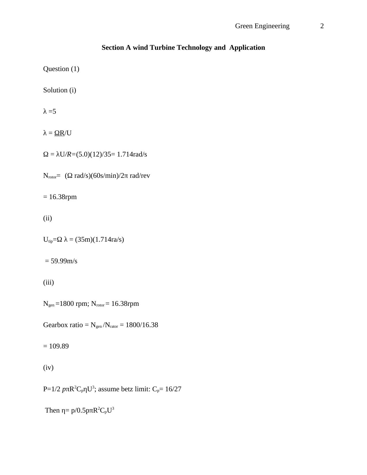
Section A wind Turbine Technology and Application
Question (1)
Solution (i)
λ =5
λ = ΩR/U
Ω = λU/R=(5.0)(12)/35= 1.714rad/s
Nrotor= (Ω rad/s)(60s/min)/2π rad/rev
= 16.38rpm
(ii)
Utip=Ω λ = (35m)(1.714ra/s)
= 59.99m/s
(iii)
Ngen =1800 rpm; Nrotor = 16.38rpm
Gearbox ratio = Ngen /Nrator = 1800/16.38
= 109.89
(iv)
P=1/2 pπR2CpηU3; assume betz limit: Cp= 16/27
Then η= p/0.5pπR2CpU3
Green Engineering 3
= 1.37
Question (2)
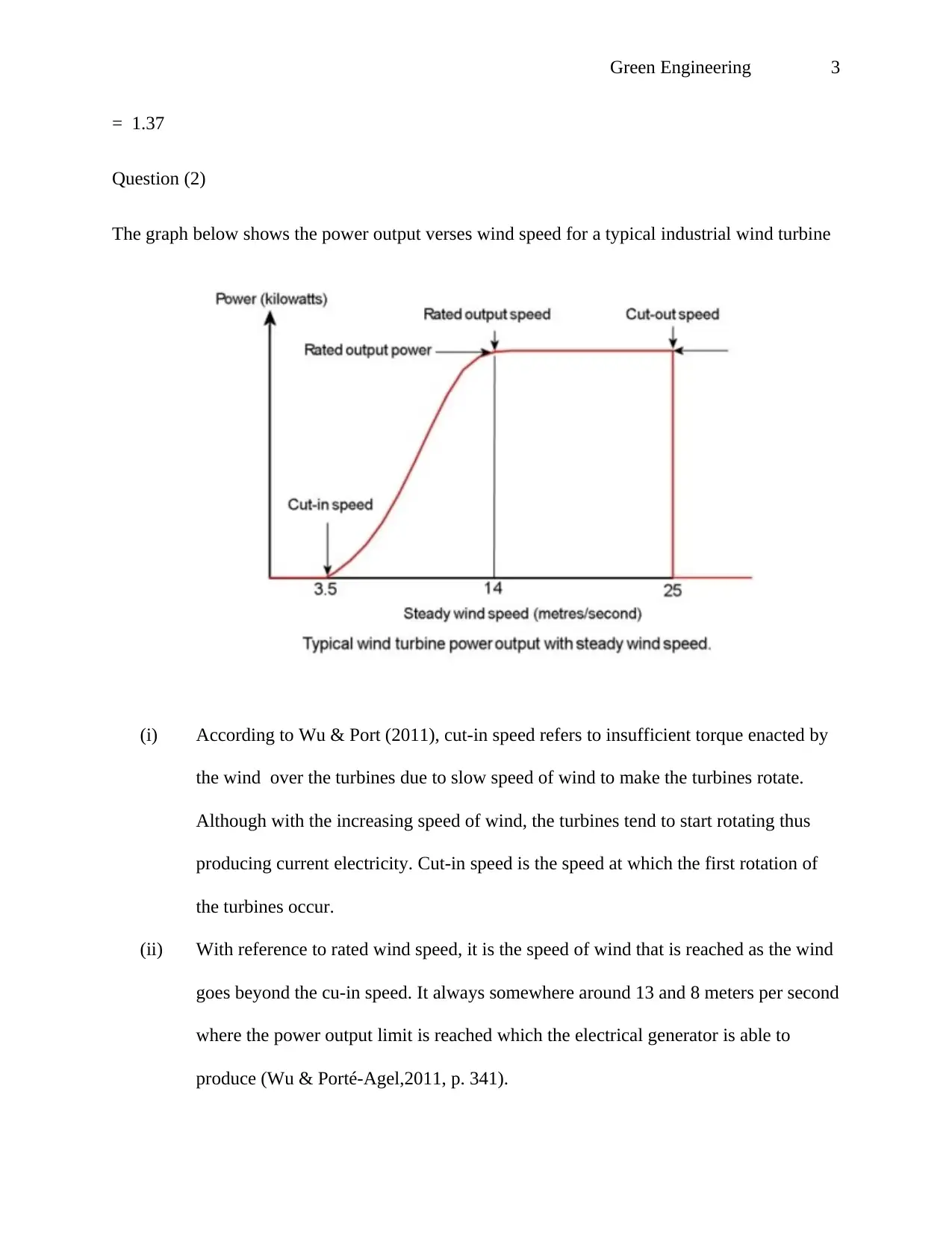
The graph below shows the power output verses wind speed for a typical industrial wind turbine
(i) According to Wu & Port (2011), cut-in speed refers to insufficient torque enacted by
the wind over the turbines due to slow speed of wind to make the turbines rotate.
Although with the increasing speed of wind, the turbines tend to start rotating thus
producing current electricity. Cut-in speed is the speed at which the first rotation of
the turbines occur.
(ii) With reference to rated wind speed, it is the speed of wind that is reached as the wind
goes beyond the cu-in speed. It always somewhere around 13 and 8 meters per second
where the power output limit is reached which the electrical generator is able to
produce (Wu & Porté-Agel,2011, p. 341).
⊘ This is a preview!⊘
Do you want full access?
Subscribe today to unlock all pages.

Trusted by 1+ million students worldwide
Green Engineering 4
(iii) Cut-out wind speed. With the speed going above the output rate of the wind speed, it
leads to increase of forces exerted at the turbines which creates the risk of destroying
the rotor. The cut out speed thus refers to the breaking system that stops the rotor and
is usually when the speed reaches 25m/s
Question 3
0 200 400 600 800 1000 1200 1400 1600 1800
0
2
4
6
8
10
12
14
16
Y-Values
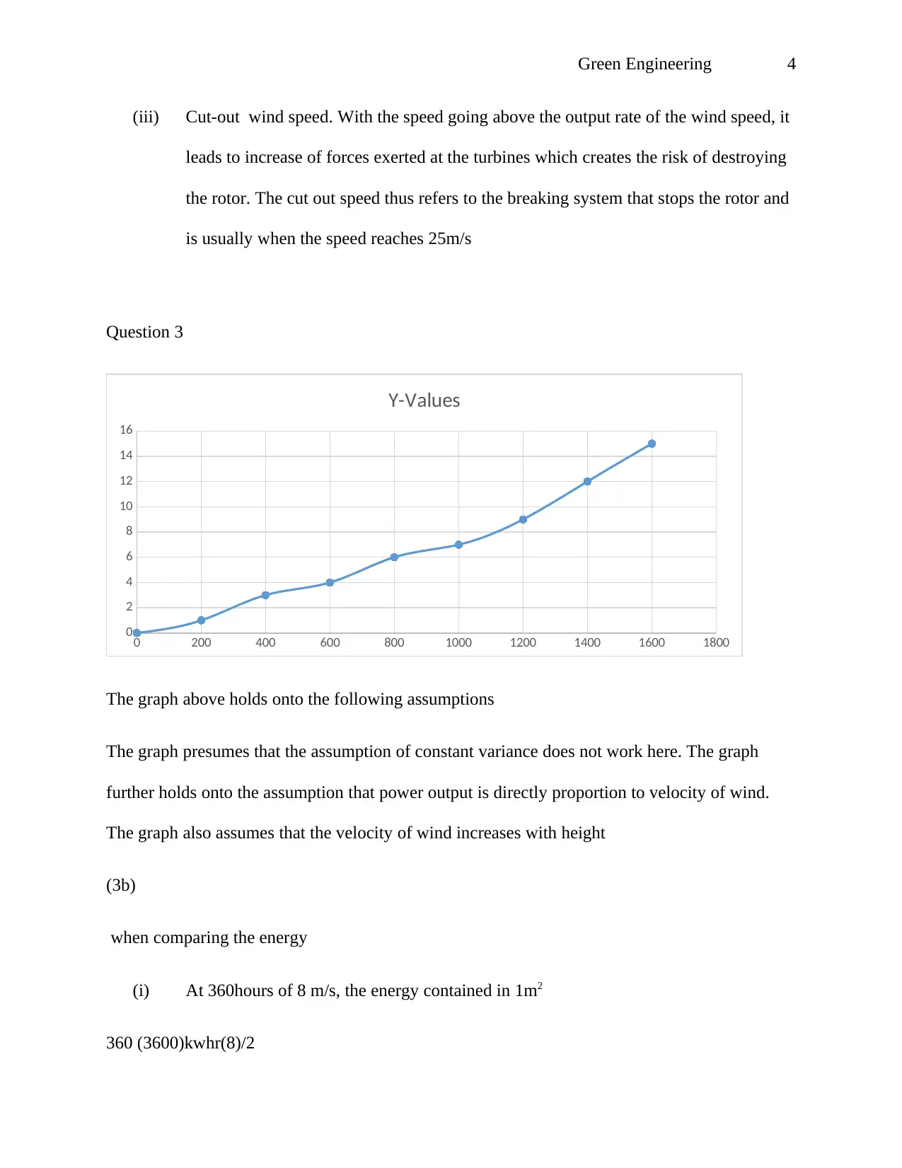
The graph above holds onto the following assumptions
The graph presumes that the assumption of constant variance does not work here. The graph
further holds onto the assumption that power output is directly proportion to velocity of wind.
The graph also assumes that the velocity of wind increases with height
(3b)
when comparing the energy
(i) At 360hours of 8 m/s, the energy contained in 1m2
360 (3600)kwhr(8)/2
Paraphrase This Document
Need a fresh take? Get an instant paraphrase of this document with our AI Paraphraser
Green Engineering 5
=8800KWh at this rate, the wind mill produces sufficient energy since is functioning at an
optimum level
(ii)
At 180 hours at 10 m/s
When the velocity of wind goes beyond the average ,the production of power is doubled eight
times the normal capacity thus from the graph above, the power produced has doubled and even
though it has only rotated for 180hrs , the energy produced equals that of 360hrs at 8m/s
Question 4
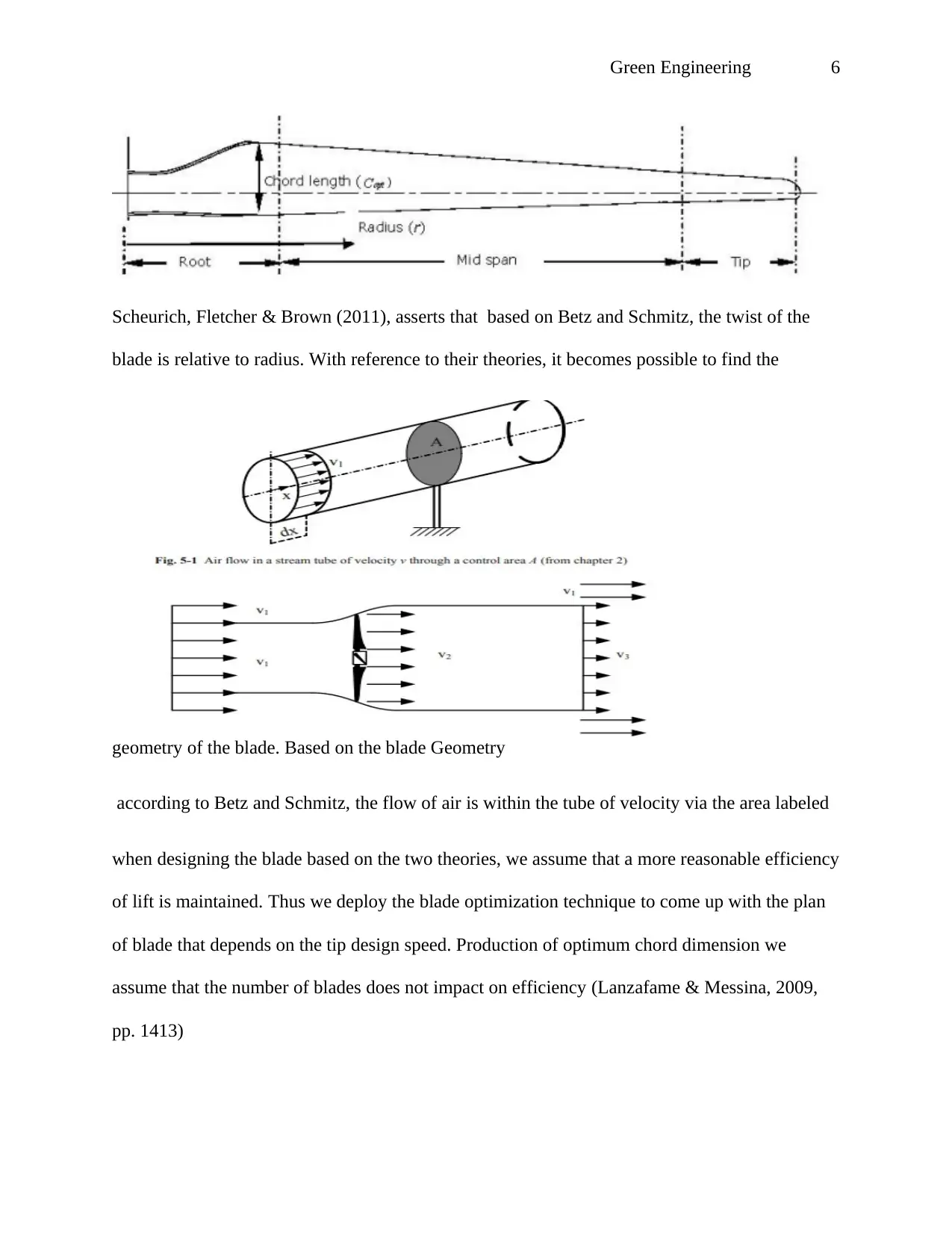
Below is a design of a turbine blade based on Betz and Schmitz for a three blade turbine.
Green Engineering 6
Scheurich, Fletcher & Brown (2011), asserts that based on Betz and Schmitz, the twist of the
blade is relative to radius. With reference to their theories, it becomes possible to find the
geometry of the blade. Based on the blade Geometry
according to Betz and Schmitz, the flow of air is within the tube of velocity via the area labeled
when designing the blade based on the two theories, we assume that a more reasonable efficiency
of lift is maintained. Thus we deploy the blade optimization technique to come up with the plan
of blade that depends on the tip design speed. Production of optimum chord dimension we
assume that the number of blades does not impact on efficiency (Lanzafame & Messina, 2009,
pp. 1413)
⊘ This is a preview!⊘
Do you want full access?
Subscribe today to unlock all pages.

Trusted by 1+ million students worldwide
Green Engineering 7
the chord length and the angle of twist are vital to consider when designing the a three blade
turbine. We need to consider the volume of the blade and the cumber. The length of the chord at
the end of a finished design become the result of the area of the wing and span of the wing. This
is through trying to set the specific load while reducing the area of the wing.
(4a)
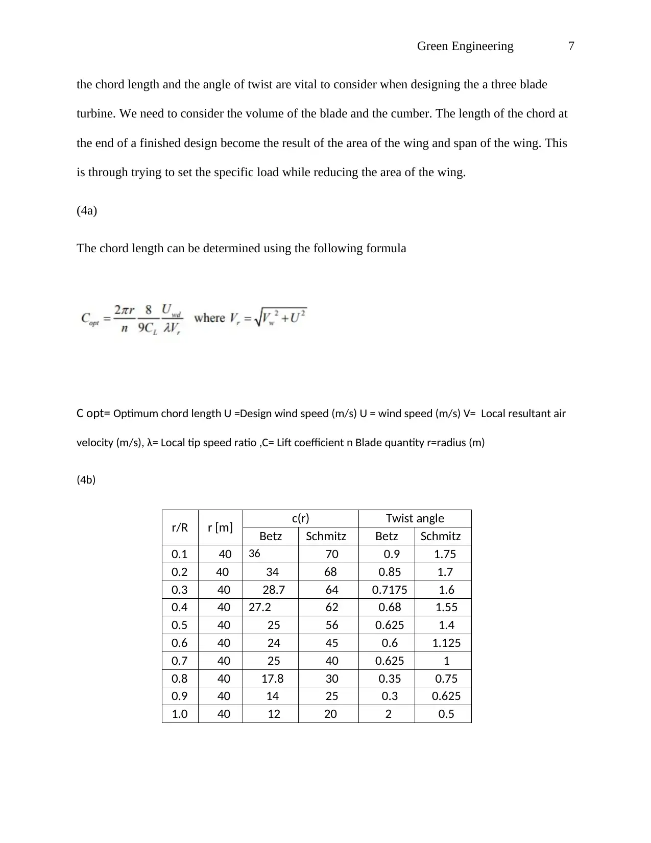
The chord length can be determined using the following formula
C opt= Optimum chord length U =Design wind speed (m/s) U = wind speed (m/s) V= Local resultant air
velocity (m/s), λ= Local tip speed ratio ,C= Lift coefficient n Blade quantity r=radius (m)
(4b)
r/R r [m] c(r) Twist angle
Betz Schmitz Betz Schmitz
0.1 40 36 70 0.9 1.75
0.2 40 34 68 0.85 1.7
0.3 40 28.7 64 0.7175 1.6
0.4 40 27.2 62 0.68 1.55
0.5 40 25 56 0.625 1.4
0.6 40 24 45 0.6 1.125
0.7 40 25 40 0.625 1
0.8 40 17.8 30 0.35 0.75
0.9 40 14 25 0.3 0.625
1.0 40 12 20 2 0.5
Paraphrase This Document
Need a fresh take? Get an instant paraphrase of this document with our AI Paraphraser
Green Engineering 8
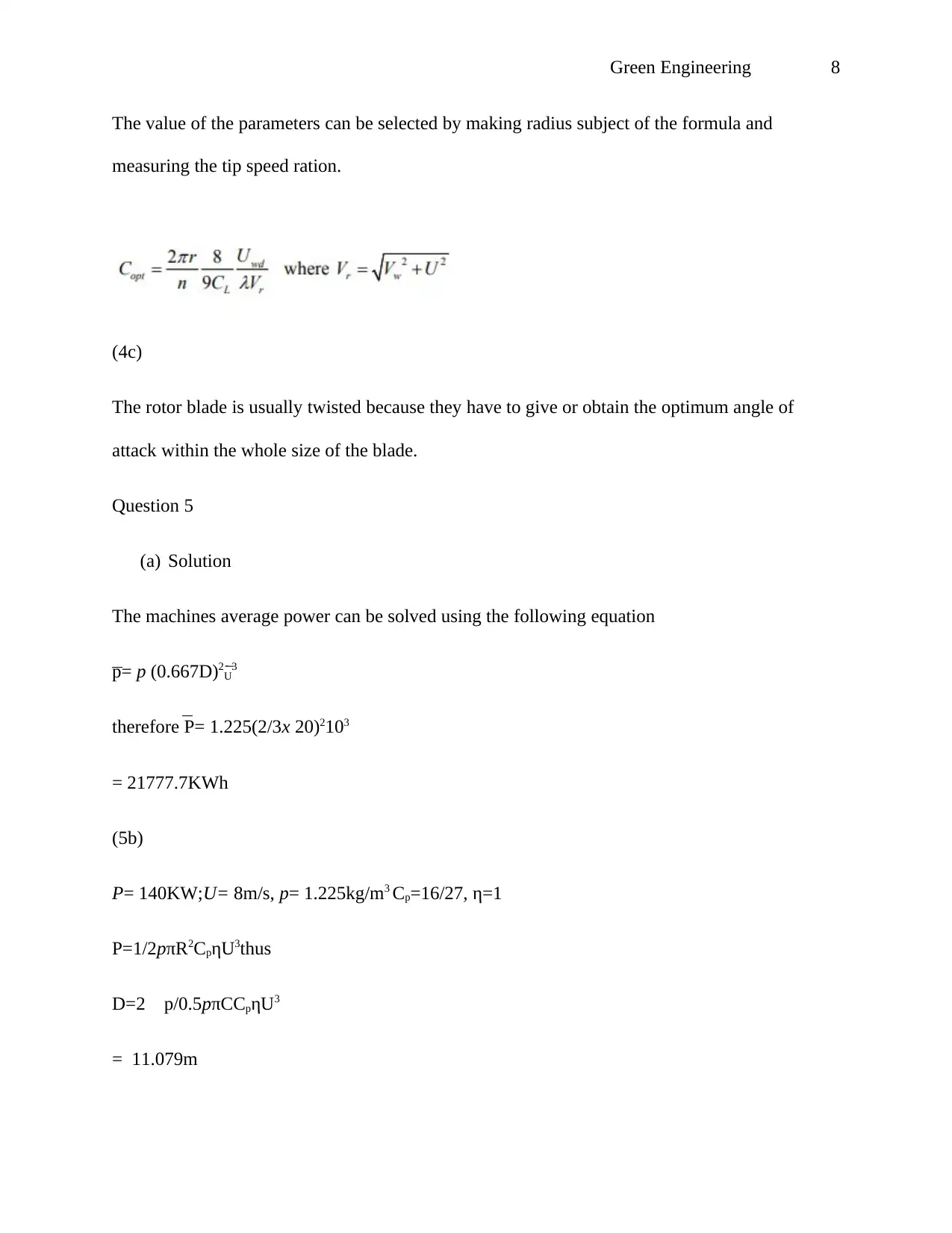
The value of the parameters can be selected by making radius subject of the formula and
measuring the tip speed ration.
(4c)
The rotor blade is usually twisted because they have to give or obtain the optimum angle of
attack within the whole size of the blade.
Question 5
(a) Solution
The machines average power can be solved using the following equation
p= p (0.667D)2U3
therefore P= 1.225(2/3x 20)2103
= 21777.7KWh
(5b)
P= 140KW;U= 8m/s, p= 1.225kg/m3 Cp=16/27, η=1
P=1/2pπR2CpηU3thus
D=2 p/0.5pπCCpηU3
= 11.079m
Green Engineering 9
Question (6)
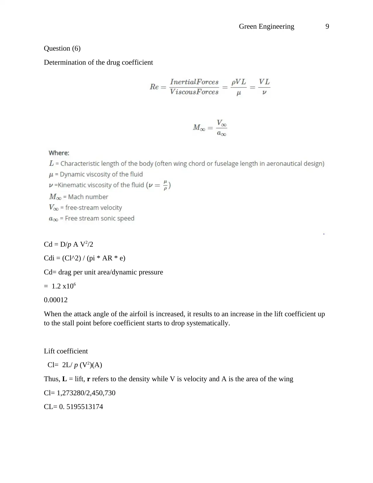
Determination of the drug coefficient
Cd = D/p A V2/2
Cdi = (Cl^2) / (pi * AR * e)
Cd= drag per unit area/dynamic pressure
= 1.2 x10⁶
0.00012
When the attack angle of the airfoil is increased, it results to an increase in the lift coefficient up
to the stall point before coefficient starts to drop systematically.
Lift coefficient
Cl= 2L/ p (V2)(A)
Thus, L = lift, r refers to the density while V is velocity and A is the area of the wing
Cl= 1,273280/2,450,730
CL= 0. 5195513174
⊘ This is a preview!⊘
Do you want full access?
Subscribe today to unlock all pages.

Trusted by 1+ million students worldwide
Green Engineering 10
Basically, the lift coefficient refers to the number used to model the complex shapes and
inclinations of airfoils on lifts. In this case, to produce the highest lift coefficient, it calls for a
look into the geometry of the aerofoil.
Basically, the lift coefficient refers to the number used to model the complex shapes and
inclinations of airfoils on lifts. In this case, to produce the highest lift coefficient, it calls for a
look into the geometry of the aerofoil.
Paraphrase This Document
Need a fresh take? Get an instant paraphrase of this document with our AI Paraphraser
Green Engineering 11
List of references
Lanzafame, R. and Messina, M. (2009) ‘Design and performance of a double-pitch wind turbine
with non-twisted blades’, Renewable Energy: An International Journal, 34(5), pp. 1413–1420
Scheurich, F., Fletcher, T. M. and Brown, R. E. (2011) ‘Effect of blade geometry on the
aerodynamic loads produced by vertical-axis wind turbines’, Proceedings of the Institution of
Mechanical Engineers -- Part A -- Power & Energy (Sage Publications, Ltd.), 225(3), pp. 327–
341.
Wu, Y.-T. and Porté-Agel, F. (2011) ‘Large-Eddy Simulation of Wind-Turbine Wakes:
Evaluation of Turbine Parametrisations’, Boundary-Layer Meteorology, 138(3), pp. 345–366.
1 out of 11
Your All-in-One AI-Powered Toolkit for Academic Success.
+13062052269
info@desklib.com
Available 24*7 on WhatsApp / Email
![[object Object]](/_next/static/media/star-bottom.7253800d.svg)
Unlock your academic potential
Copyright © 2020–2026 A2Z Services. All Rights Reserved. Developed and managed by ZUCOL.

