Design and Fabrication of a Grinding Attachment for Lathe Machine Tool
VerifiedAdded on 2023/06/14
|6
|2205
|382
Report
AI Summary
This report details the design and fabrication of a grinding attachment for a lathe machine tool, aiming to integrate grinding operations for fine surface finishes directly onto a lathe. The project focuses on reducing workpiece loading and unloading time while maintaining high precision. Key aspects covered include the selection of an appropriate grinding wheel based on material and dimensional requirements, ensuring rigidity in the attachment design to minimize vibrations from the motor, and conducting stress analysis on critical components using INVENTOR software. The report also outlines the fabrication process, including frame construction, coupling assembly, and shaft manufacturing. The final attachment is evaluated for accuracy, with results demonstrating a reduction in human effort and lead time, achieving an accuracy of up to 20 microns.
International Journal of Science, Technology & Management www.ijstm.com
Volume No.04, Issue No. 04, April 2015 ISSN (online): 2394-1537
62 | P a g e
DESIGN AND FABRICATION OF GRINDING
ATTACHMENT FOR LATHE MACHINE TOOL
Pratik Chavan1, Sanket Desale2, Ninad Kantela3, Priyanka Thanage4
Prasad Bari5
1,2,3,4B.E. Students, Fr. C Rodrigues Institute of Technology, Vashi Navi Mumbai, (India)
5Assistant Professor, Department of Mechanical Engineering
Fr. C Rodrigues Institute of Technology, Vashi Navi Mumbai, (India)
ABSTRACT
Grinding operation is performed to obtain a fine surface finish after performing turning operation on lathe
machine for cylindrical jobs. This is done to obtain required dimensions of part to be used in any assembly.
Thus to perform these two operations on same machine the attachment is designed. To verify the design the
attachment is fabricated.
This work describes an attempt to decrease the time in loading and unloading of workpeice with desired surface
finish. The report describes the selection of wheel for grinding. It also considers the rigidity of design, damping
of vibration due to motor speed and stress analysis of critical part of design, which is analyzed on INVENTOR
software and compared with theoretical calculations. It also lists the various operations performed to fabricate
the attachment. The results are obtained in form of tolerance limits which are compared with results of
individual grinding machine operation on different machine and the conclusion are stated.
Keywords: Grinding, Cylindricity, Rigidity
I. INTRODUCTION
Lathe has always been the mother of all machines before the invention of CNC machines. The turning operation
on lathe is most frequently performed, and then it’s transferred to grinding machine for fine surface finish. The
time required to do this is generally high and loading and unloading of job causes human fautige. Thus
combining these two operations on single machine would benefit and this led to think of grinding on lathe
machine. The grinding operation is done using abrasive wheel, grinder which provides fine surface finish. The
grinding wheel differs for different materials to be grinded which is made up of abrasives, bond, grit, grade and
structure [1]. In this paper we have selected the required grinding wheel depending on workpeice to be used.
The main aim of project is to obtain an accuracy of 20microns. Since grinding requires high surface finish thus
proper motor speed is selected as required [2]. Since the motor will run at high rpm lot of vibrations will be
generated, thus it will be necessary to damp these vibrations using damper [8].Additional to it appropriate
rigidity should be provided to clamp the motor on lathe bed.
Paraphrase This Document
Need a fresh take? Get an instant paraphrase of this document with our AI Paraphraser
International Journal of Science, Technology & Management www.ijstm.com
Volume No.04, Issue No. 04, April 2015 ISSN (online): 2394-1537
63 | P a g e
II. SELECTION OF GRINDING WHEEL
Grinding wheel is specified by its grit, grade and structure. For different type of work material and for different
dimensions, the requirements of a grinding wheel are different. Thus it is important to select a proper grinding
wheel. Following are some major specifications of grinding wheel.
1.1 Abrasives
For high tensile strength the abrasive should be tough and should not get fractured easily. Thus Aluminium
oxide was selected as an abrasive, assuming maximum work to be done on mild steel.
1.2 Grit
Grit is grain size. Smaller the grit finer is the surface finish. For high stock removal rate and better control of
surface finish Grain size should be 30-60. Therefore grit is selected as 60.
1.3 Grade
Grade is to define hardness of the bond holding the grains together. For better compromise between soft and
hard bond so that wheel wear and cost will be less intermediate grade P is selected.
1.4 Structure
Structure is the void spacing between the grains. Lesser the structure, higher is the density of grains on the
wheel. Densely packed grains are required for fine cuts. Therefore structure is selected as 5.
1.5 Bond
Bond is the type of adhesive used to hold grains together on the wheel. It depends on rate of stock removal,
rigidity and required precision. For high stock removal, rigidity and suitable precision grinding vitrified bonds
are preferred. Therefore V99 bond is selected.
Selected wheel specification is A60P5V99
III. SELECTION OF MOTOR
For this attachment, it is necessary to select drive with proper speed and torque. The dimensions of grinding
wheel and speed of the motor are interrelated. For grinding wheel with 150mm diameter, desired speed is 2880
rpm. Thus 3phase AC motor with power of 0.75 HP and 2880 rpm is selected.
IV. DESIGN
To achieve the objective of this project some important issues must be focused which will guarantee accuracy of
20microns and desired fine surface finish. Following are three major issues
4.1 Absorption of Vibrations
Due to a very high speed of motor, there are a lot of vibrations involved. Static deflection was found to be
0.0126m. The effectiveness of the isolaton produced by the isolator is characterized by transmissibility which is
defined as the ratio of force transmitted by an isolator to the exciting force due to machine. Selection of an
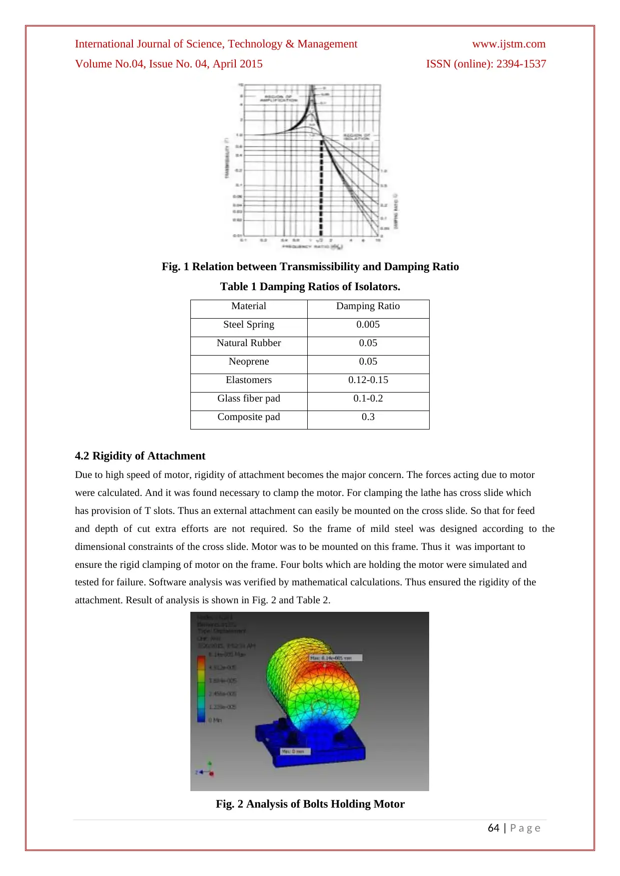
isolator is done on the basis of damping ratio. Following graph shows the relation between transmissibility and
damping ratios from the graph shown below, suitable damping ratio was found to be 0.05. Thus rubber was
selected as an isolator.
International Journal of Science, Technology & Management www.ijstm.com
Volume No.04, Issue No. 04, April 2015 ISSN (online): 2394-1537
64 | P a g e
Fig. 1 Relation between Transmissibility and Damping Ratio
Table 1 Damping Ratios of Isolators.
Material Damping Ratio
Steel Spring 0.005
Natural Rubber 0.05
Neoprene 0.05
Elastomers 0.12-0.15
Glass fiber pad 0.1-0.2
Composite pad 0.3
4.2 Rigidity of Attachment
Due to high speed of motor, rigidity of attachment becomes the major concern. The forces acting due to motor
were calculated. And it was found necessary to clamp the motor. For clamping the lathe has cross slide which
has provision of T slots. Thus an external attachment can easily be mounted on the cross slide. So that for feed
and depth of cut extra efforts are not required. So the frame of mild steel was designed according to the
dimensional constraints of the cross slide. Motor was to be mounted on this frame. Thus it was important to
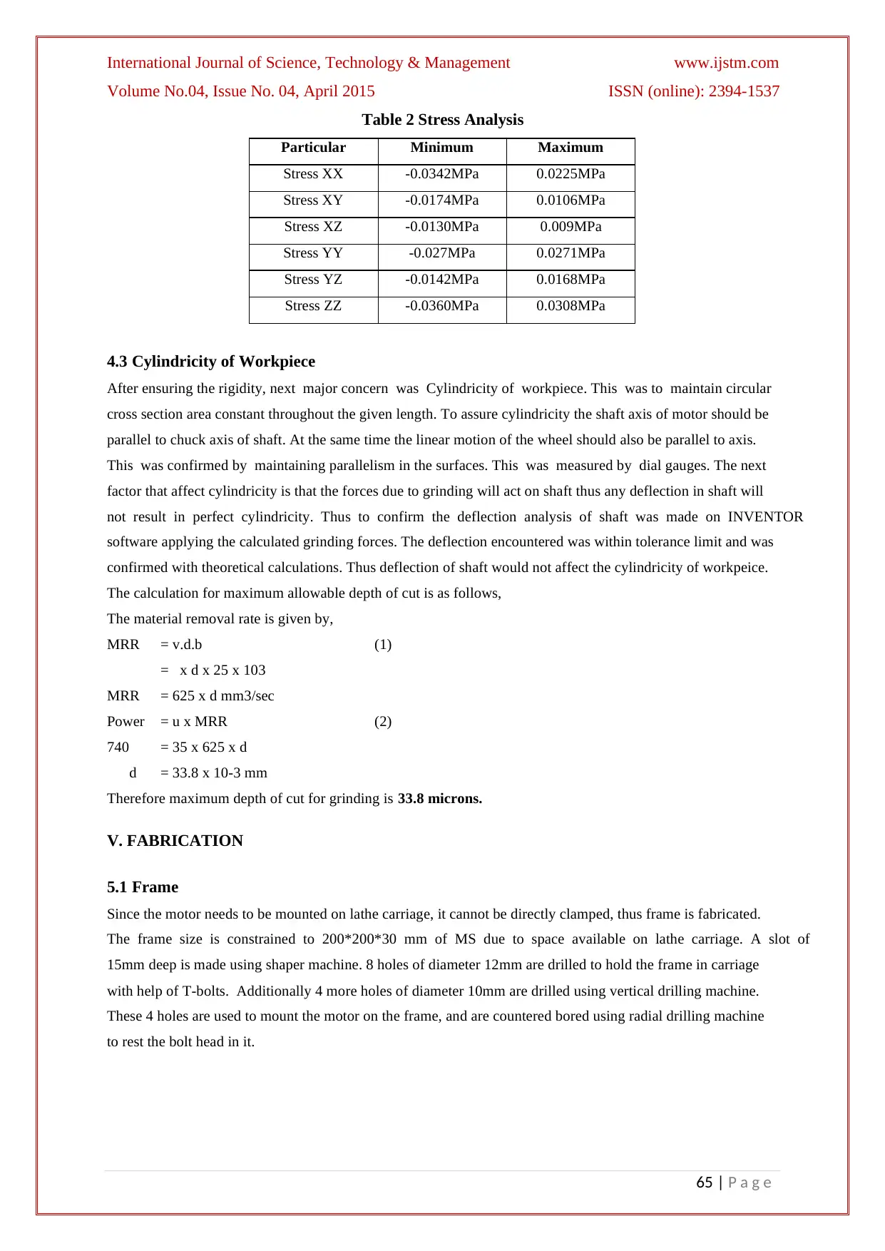
ensure the rigid clamping of motor on the frame. Four bolts which are holding the motor were simulated and
tested for failure. Software analysis was verified by mathematical calculations. Thus ensured the rigidity of the
attachment. Result of analysis is shown in Fig. 2 and Table 2.
Fig. 2 Analysis of Bolts Holding Motor
⊘ This is a preview!⊘
Do you want full access?
Subscribe today to unlock all pages.

Trusted by 1+ million students worldwide
International Journal of Science, Technology & Management www.ijstm.com
Volume No.04, Issue No. 04, April 2015 ISSN (online): 2394-1537
65 | P a g e
Table 2 Stress Analysis
Particular Minimum Maximum
Stress XX -0.0342MPa 0.0225MPa
Stress XY -0.0174MPa 0.0106MPa
Stress XZ -0.0130MPa 0.009MPa
Stress YY -0.027MPa 0.0271MPa
Stress YZ -0.0142MPa 0.0168MPa
Stress ZZ -0.0360MPa 0.0308MPa
4.3 Cylindricity of Workpiece
After ensuring the rigidity, next major concern was Cylindricity of workpiece. This was to maintain circular
cross section area constant throughout the given length. To assure cylindricity the shaft axis of motor should be
parallel to chuck axis of shaft. At the same time the linear motion of the wheel should also be parallel to axis.
This was confirmed by maintaining parallelism in the surfaces. This was measured by dial gauges. The next
factor that affect cylindricity is that the forces due to grinding will act on shaft thus any deflection in shaft will
not result in perfect cylindricity. Thus to confirm the deflection analysis of shaft was made on INVENTOR
software applying the calculated grinding forces. The deflection encountered was within tolerance limit and was
confirmed with theoretical calculations. Thus deflection of shaft would not affect the cylindricity of workpeice.
The calculation for maximum allowable depth of cut is as follows,
The material removal rate is given by,
MRR = v.d.b (1)
= x d x 25 x 103
MRR = 625 x d mm3/sec
Power = u x MRR (2)
740 = 35 x 625 x d
d = 33.8 x 10⁻³ mm
Therefore maximum depth of cut for grinding is 33.8 microns.
V. FABRICATION
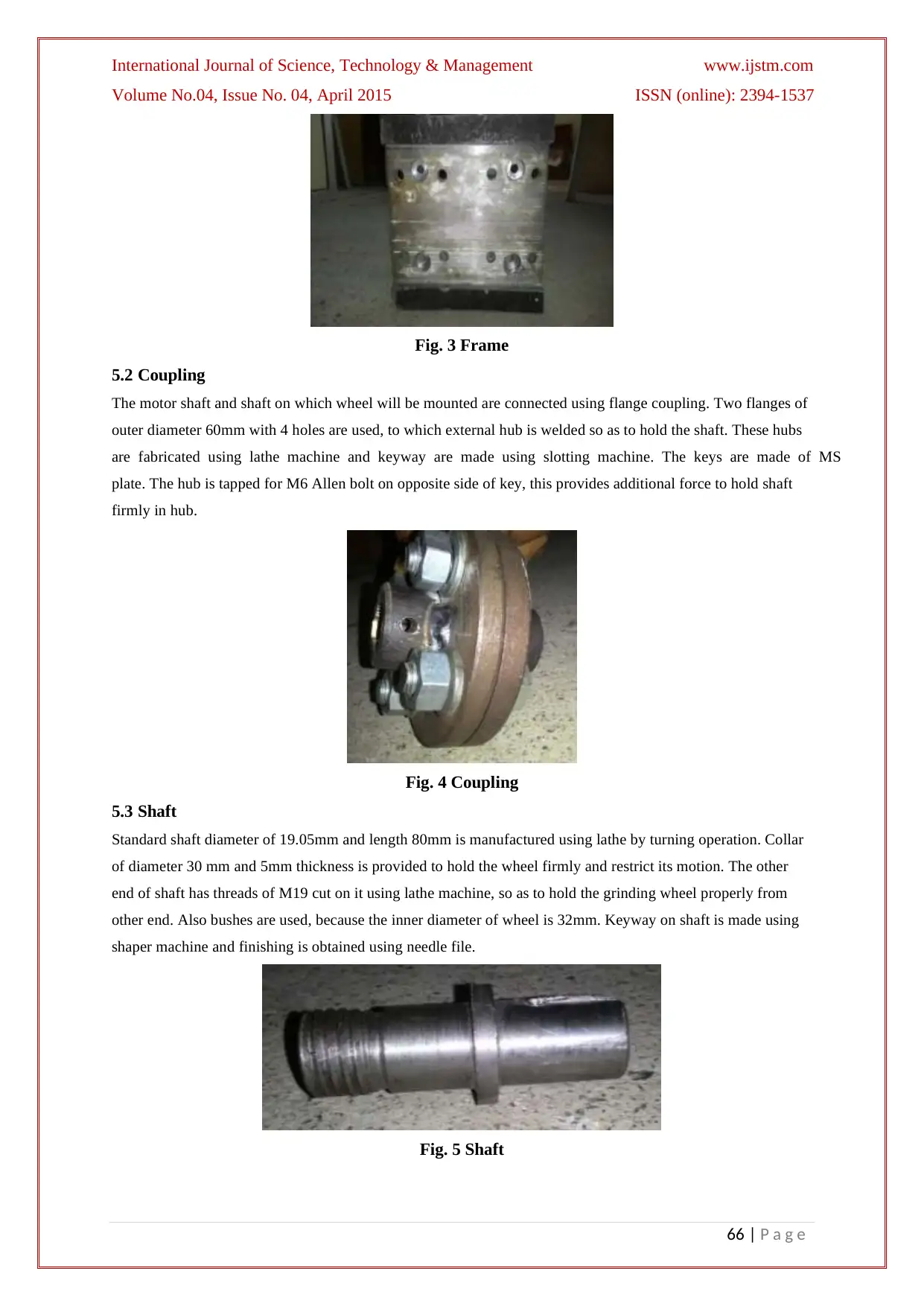
5.1 Frame
Since the motor needs to be mounted on lathe carriage, it cannot be directly clamped, thus frame is fabricated.
The frame size is constrained to 200*200*30 mm of MS due to space available on lathe carriage. A slot of
15mm deep is made using shaper machine. 8 holes of diameter 12mm are drilled to hold the frame in carriage
with help of T-bolts. Additionally 4 more holes of diameter 10mm are drilled using vertical drilling machine.
These 4 holes are used to mount the motor on the frame, and are countered bored using radial drilling machine
to rest the bolt head in it.
Paraphrase This Document
Need a fresh take? Get an instant paraphrase of this document with our AI Paraphraser
International Journal of Science, Technology & Management www.ijstm.com
Volume No.04, Issue No. 04, April 2015 ISSN (online): 2394-1537
66 | P a g e
Fig. 3 Frame
5.2 Coupling
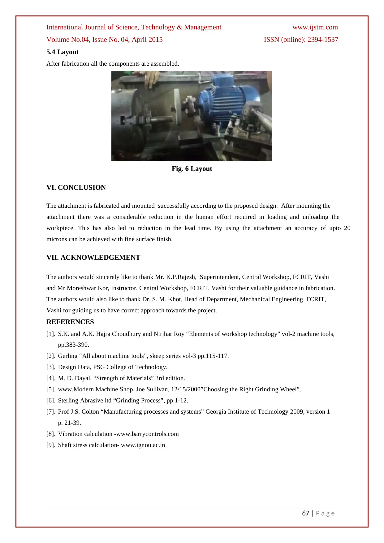
The motor shaft and shaft on which wheel will be mounted are connected using flange coupling. Two flanges of
outer diameter 60mm with 4 holes are used, to which external hub is welded so as to hold the shaft. These hubs
are fabricated using lathe machine and keyway are made using slotting machine. The keys are made of MS
plate. The hub is tapped for M6 Allen bolt on opposite side of key, this provides additional force to hold shaft
firmly in hub.
Fig. 4 Coupling
5.3 Shaft
Standard shaft diameter of 19.05mm and length 80mm is manufactured using lathe by turning operation. Collar
of diameter 30 mm and 5mm thickness is provided to hold the wheel firmly and restrict its motion. The other
end of shaft has threads of M19 cut on it using lathe machine, so as to hold the grinding wheel properly from
other end. Also bushes are used, because the inner diameter of wheel is 32mm. Keyway on shaft is made using
shaper machine and finishing is obtained using needle file.
Fig. 5 Shaft
International Journal of Science, Technology & Management www.ijstm.com
Volume No.04, Issue No. 04, April 2015 ISSN (online): 2394-1537
67 | P a g e
5.4 Layout
After fabrication all the components are assembled.
Fig. 6 Layout
VI. CONCLUSION
The attachment is fabricated and mounted successfully according to the proposed design. After mounting the
attachment there was a considerable reduction in the human effort required in loading and unloading the
workpiece. This has also led to reduction in the lead time. By using the attachment an accuracy of upto 20
microns can be achieved with fine surface finish.
VII. ACKNOWLEDGEMENT
The authors would sincerely like to thank Mr. K.P.Rajesh, Superintendent, Central Workshop, FCRIT, Vashi
and Mr.Moreshwar Kor, Instructor, Central Workshop, FCRIT, Vashi for their valuable guidance in fabrication.
The authors would also like to thank Dr. S. M. Khot, Head of Department, Mechanical Engineering, FCRIT,
Vashi for guiding us to have correct approach towards the project.
REFERENCES
[1]. S.K. and A.K. Hajra Choudhury and Nirjhar Roy “Elements of workshop technology” vol-2 machine tools,
pp.383-390.
[2]. Gerling “All about machine tools”, skeep series vol-3 pp.115-117.
[3]. Design Data, PSG College of Technology.
[4]. M. D. Dayal, “Strength of Materials” 3rd edition.
[5]. www.Modern Machine Shop, Joe Sullivan, 12/15/2000”Choosing the Right Grinding Wheel”.
[6]. Sterling Abrasive ltd “Grinding Process”, pp.1-12.
[7]. Prof J.S. Colton “Manufacturing processes and systems” Georgia Institute of Technology 2009, version 1
p. 21-39.
[8]. Vibration calculation -www.barrycontrols.com
[9]. Shaft stress calculation- www.ignou.ac.in
⊘ This is a preview!⊘
Do you want full access?
Subscribe today to unlock all pages.

Trusted by 1+ million students worldwide
1 out of 6
Your All-in-One AI-Powered Toolkit for Academic Success.
+13062052269
info@desklib.com
Available 24*7 on WhatsApp / Email
![[object Object]](/_next/static/media/star-bottom.7253800d.svg)
Unlock your academic potential
Copyright © 2020–2026 A2Z Services. All Rights Reserved. Developed and managed by ZUCOL.

