BE301-GSM Cellular Mobile Radio Base Station Network Design 2018
VerifiedAdded on 2023/06/11
|13
|2215
|457
Report
AI Summary
This document presents a design of a GSM cellular mobile radio base station network, following GSM network regulations. It covers essential aspects of PLMN (public land mobile network) planning using simulation software, emphasizing the importance of pre-implementation design. The report discusses GSM architecture, frequency bands (GSM 900 and GSM 1800), and technologies like UMTS. It addresses cellular planning, including coarse planning, coverage planning, interference testing, and dynamic channel assignments. The design incorporates technical specifications, geographical data from site surveys, frequency planning using ARFCN, and tele traffic capacity planning. The CelPlanner Suite software is utilized for network testing across various terrains. The discussion critiques cell size impacts on user capacity and handover complexity. References to various sources and standards are provided.
Design of GSM Cellular Mobile Radio Base Station Network 1
Melbourne Institute of Technology
SCHOOL OF INFORMATION TECHNOLOGY & ENGINEERING
BE301-TELECOMMUNICATION MODELLING AND
SIMULATION
Assignment 2
Term 1, 2018
Design of GSM Cellular Mobile Radio Base Station
Network
Student Name
Student Registration Number
Professor (tutor)
Date of Submission
Melbourne Institute of Technology
SCHOOL OF INFORMATION TECHNOLOGY & ENGINEERING
BE301-TELECOMMUNICATION MODELLING AND
SIMULATION
Assignment 2
Term 1, 2018
Design of GSM Cellular Mobile Radio Base Station
Network
Student Name
Student Registration Number
Professor (tutor)
Date of Submission
Paraphrase This Document
Need a fresh take? Get an instant paraphrase of this document with our AI Paraphraser
Design of GSM Cellular Mobile Radio Base Station Network 2
INTRODUCTION
It is very important to plan a public land mobile network, PLMN, on simulation software before
performing the implementation on the ground. The design and implementation of a Base Station
Network follows from the GSM network regulations document in the Request for Comments, RFCs. The
mobile communication system on land is defined in cells and sectors as discussed further in the
literature review. The GSM architecture for the PLMN has the base station subsystem which links to the
mobile switching center. The base station transceivers are the first line connection to the user or mobile
equipment. The BTS performs location updates and connects to the user equipment to ensure that the
mobile user is connected to the cellular network. The PLMN uses microwaves and radio waves to
transmit message signals over the atmosphere. The use of GSM technology allows for the voice
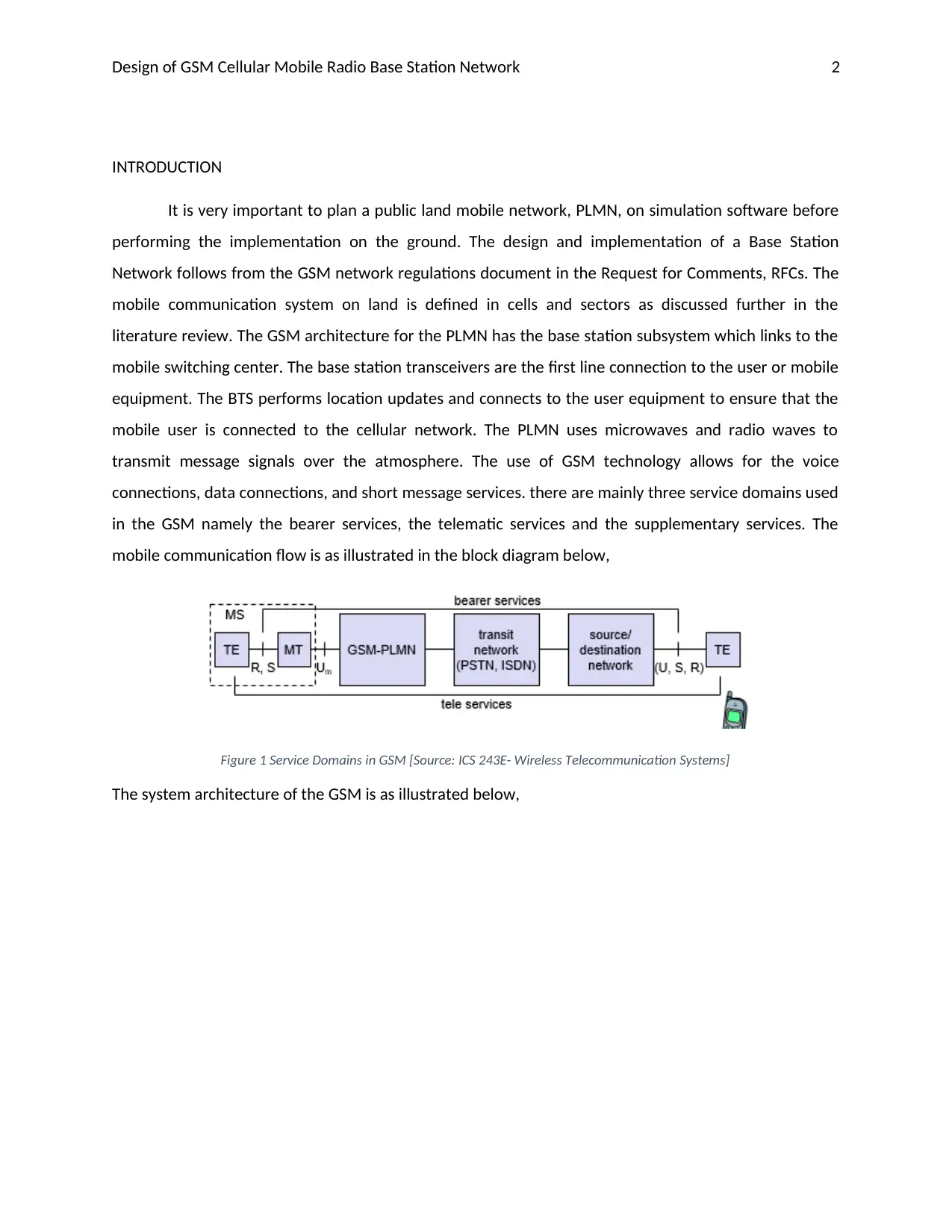
connections, data connections, and short message services. there are mainly three service domains used
in the GSM namely the bearer services, the telematic services and the supplementary services. The
mobile communication flow is as illustrated in the block diagram below,
Figure 1 Service Domains in GSM [Source: ICS 243E- Wireless Telecommunication Systems]
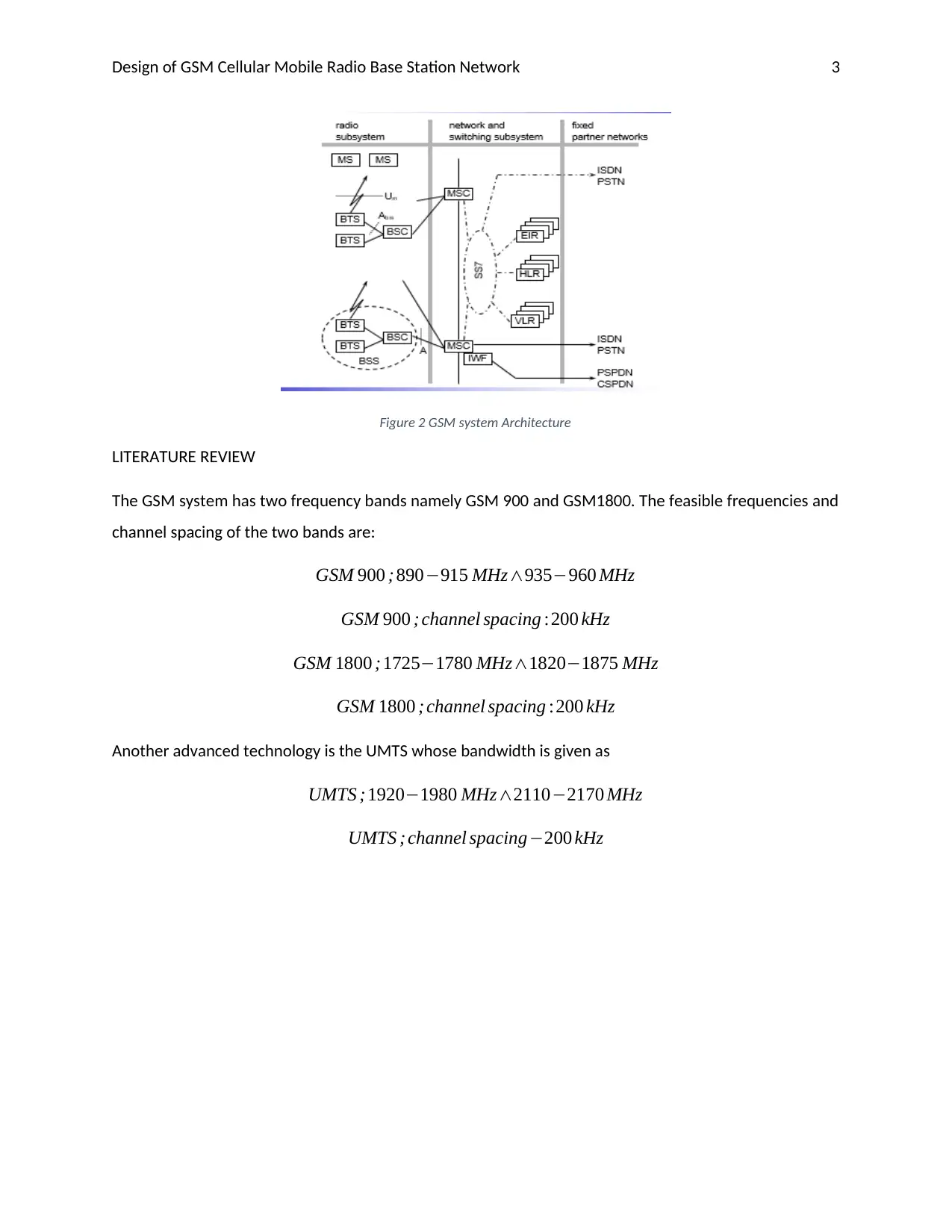
The system architecture of the GSM is as illustrated below,
Design of GSM Cellular Mobile Radio Base Station Network 3
Figure 2 GSM system Architecture
LITERATURE REVIEW
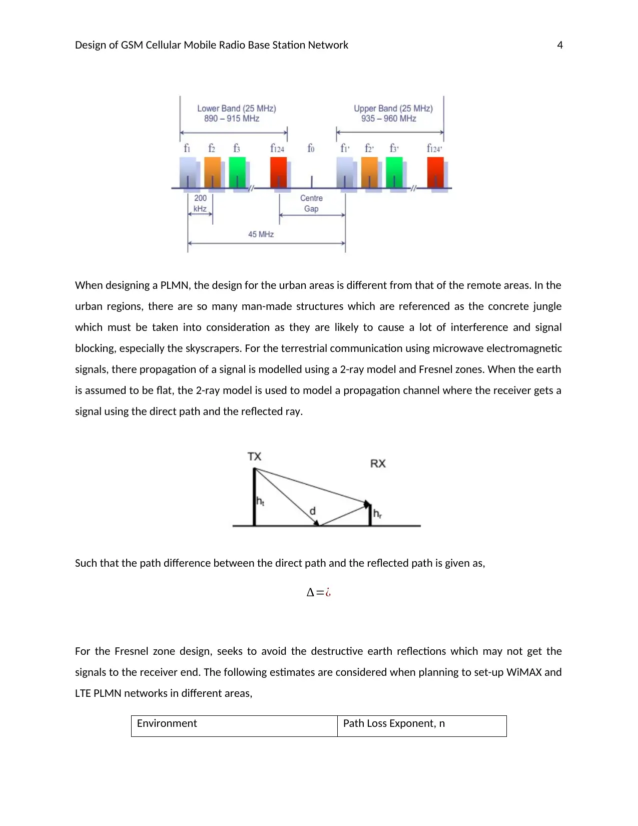
The GSM system has two frequency bands namely GSM 900 and GSM1800. The feasible frequencies and
channel spacing of the two bands are:
GSM 900 ; 890−915 MHz∧935−960 MHz
GSM 900 ; channel spacing :200 kHz
GSM 1800 ; 1725−1780 MHz∧1820−1875 MHz
GSM 1800 ; channel spacing :200 kHz
Another advanced technology is the UMTS whose bandwidth is given as
UMTS ;1920−1980 MHz∧2110−2170 MHz
UMTS ; channel spacing−200 kHz
⊘ This is a preview!⊘
Do you want full access?
Subscribe today to unlock all pages.

Trusted by 1+ million students worldwide
Design of GSM Cellular Mobile Radio Base Station Network 4
When designing a PLMN, the design for the urban areas is different from that of the remote areas. In the
urban regions, there are so many man-made structures which are referenced as the concrete jungle
which must be taken into consideration as they are likely to cause a lot of interference and signal
blocking, especially the skyscrapers. For the terrestrial communication using microwave electromagnetic
signals, there propagation of a signal is modelled using a 2-ray model and Fresnel zones. When the earth
is assumed to be flat, the 2-ray model is used to model a propagation channel where the receiver gets a
signal using the direct path and the reflected ray.
Such that the path difference between the direct path and the reflected path is given as,
∆=¿
For the Fresnel zone design, seeks to avoid the destructive earth reflections which may not get the
signals to the receiver end. The following estimates are considered when planning to set-up WiMAX and
LTE PLMN networks in different areas,
Environment Path Loss Exponent, n
Paraphrase This Document
Need a fresh take? Get an instant paraphrase of this document with our AI Paraphraser
Design of GSM Cellular Mobile Radio Base Station Network 5
Free Space 2
Ideal Specular reflection 4
Urban Cells 2.7-3.5
Urban cells (shadowed) 3-5
In building (line of sight) 1.6 – 1.8
In building (obstructed path) 4 -6
In factory (obstructed path) 2-3
During the network planning, one is able to determine whether a network roll out in a given region is
feasible or not depending on certain parameters under study. It is possible that during such a
transmission, the message signals encounter some path losses while propagating. Some of the effects of
atmospheric conditions on the message signal include the message signal scattering, reflection,
diffraction, and fading. The impact is greater when the atmosphere is very humid or in rainy periods.
CELLULAR PLANNING PROCESS
(i) Coarse planning on terrestrial communication.
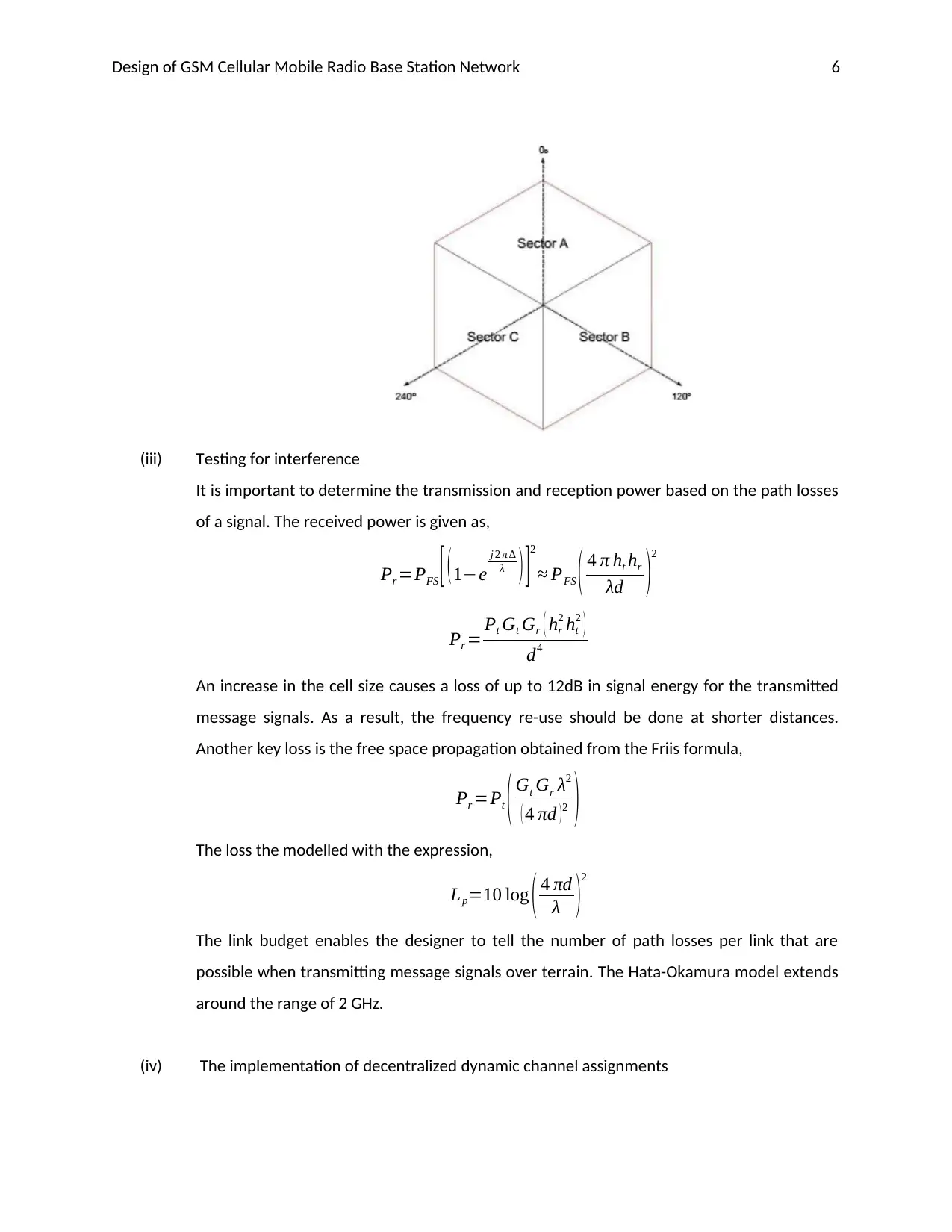
In the cell design, each base station is designed to implement the space division multiplex.
Each base station covers a transmission area or cell and it is allocated a portion of the total
channels available. Clusters are formed of the base stations close to each other using
different frequencies.
(ii) Coverage planning – deals with the extent to which a base station will cover. In some
clusters, there are fewer base stations with omni-coverage along very long distances. The
timing advance for the adaptive frame synchronization is given as,
timin gadvance= Advanc eT xtime
x tpropagatio ndelay
The design takes into consideration the frequency hopping in the efforts to utilize the
frequency spectrum comprehensively. The base station antenna height is a key factor of
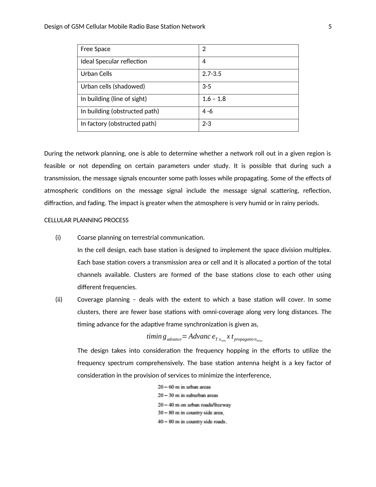
consideration in the provision of services to minimize the interference,
Design of GSM Cellular Mobile Radio Base Station Network 6
(iii) Testing for interference
It is important to determine the transmission and reception power based on the path losses
of a signal. The received power is given as,
Pr =PFS [ (1−e
j 2 π ∆
λ ) ]2
≈ PFS ( 4 π ht hr
λd )2
Pr = Pt Gt Gr ( hr
2 ht
2 )
d4
An increase in the cell size causes a loss of up to 12dB in signal energy for the transmitted
message signals. As a result, the frequency re-use should be done at shorter distances.
Another key loss is the free space propagation obtained from the Friis formula,
Pr =Pt ( Gt Gr λ2
( 4 πd )2 )
The loss the modelled with the expression,
Lp=10 log ( 4 πd
λ )
2
The link budget enables the designer to tell the number of path losses per link that are
possible when transmitting message signals over terrain. The Hata-Okamura model extends
around the range of 2 GHz.
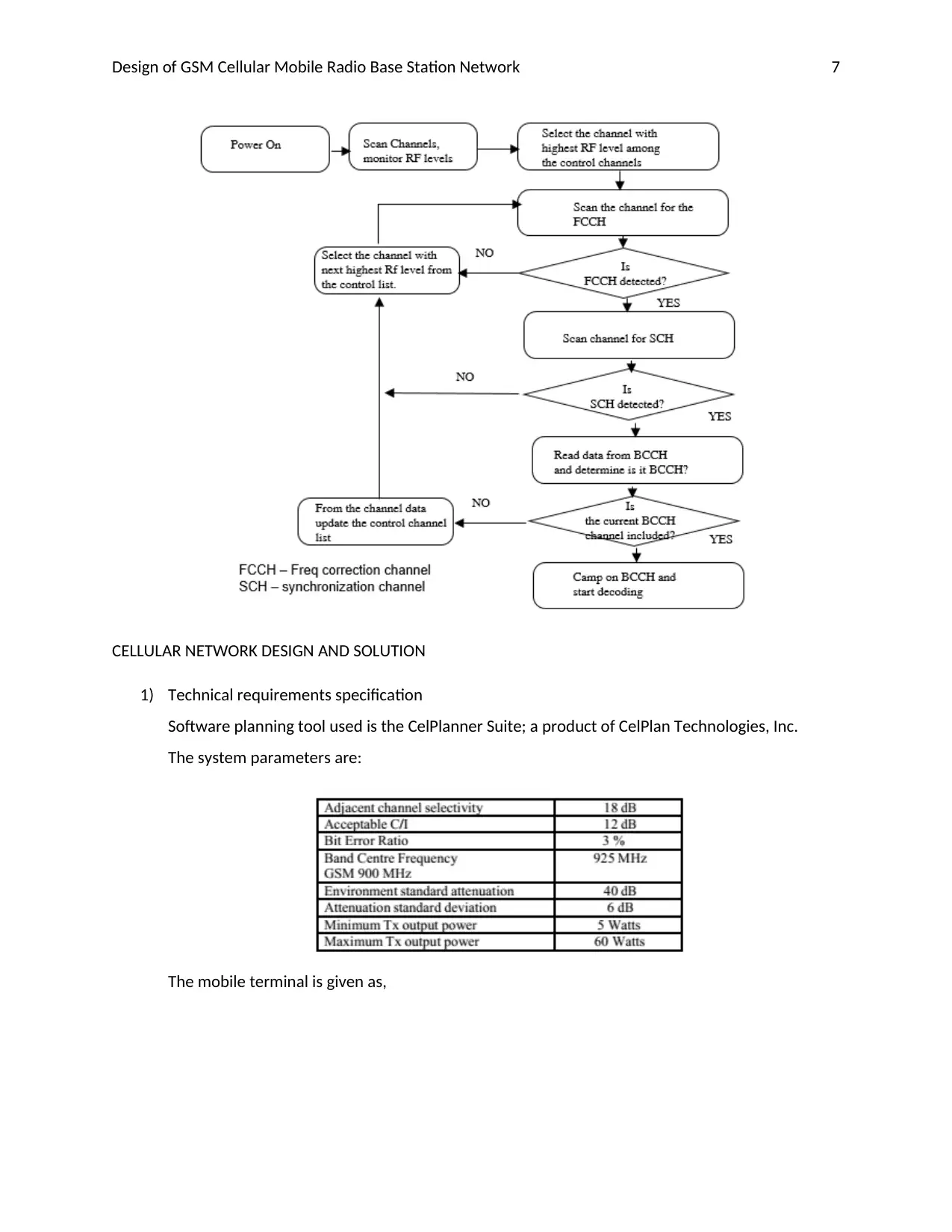
(iv) The implementation of decentralized dynamic channel assignments
⊘ This is a preview!⊘
Do you want full access?
Subscribe today to unlock all pages.

Trusted by 1+ million students worldwide
Design of GSM Cellular Mobile Radio Base Station Network 7
CELLULAR NETWORK DESIGN AND SOLUTION
1) Technical requirements specification
Software planning tool used is the CelPlanner Suite; a product of CelPlan Technologies, Inc.
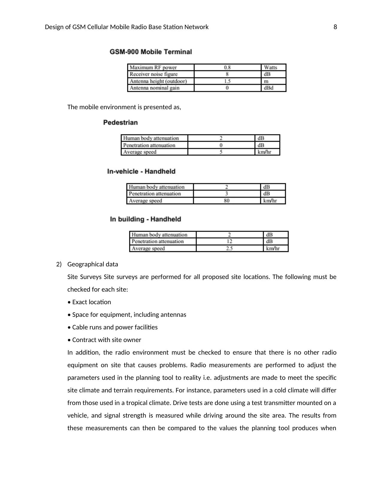
The system parameters are:
The mobile terminal is given as,
CELLULAR NETWORK DESIGN AND SOLUTION
1) Technical requirements specification
Software planning tool used is the CelPlanner Suite; a product of CelPlan Technologies, Inc.
The system parameters are:
The mobile terminal is given as,
Paraphrase This Document
Need a fresh take? Get an instant paraphrase of this document with our AI Paraphraser
Design of GSM Cellular Mobile Radio Base Station Network 8
The mobile environment is presented as,
2) Geographical data
Site Surveys Site surveys are performed for all proposed site locations. The following must be
checked for each site:
• Exact location
• Space for equipment, including antennas
• Cable runs and power facilities
• Contract with site owner
In addition, the radio environment must be checked to ensure that there is no other radio
equipment on site that causes problems. Radio measurements are performed to adjust the
parameters used in the planning tool to reality i.e. adjustments are made to meet the specific
site climate and terrain requirements. For instance, parameters used in a cold climate will differ
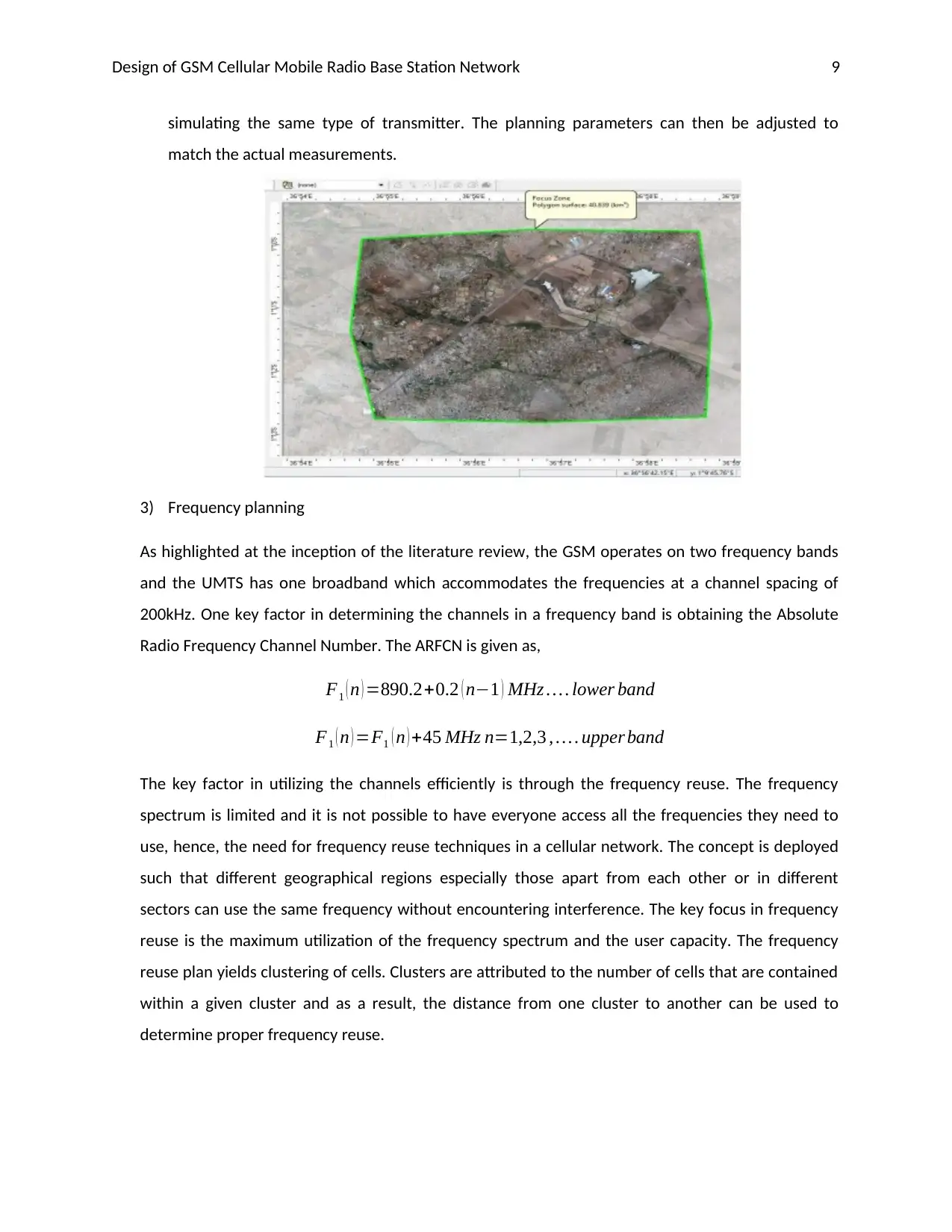
from those used in a tropical climate. Drive tests are done using a test transmitter mounted on a
vehicle, and signal strength is measured while driving around the site area. The results from
these measurements can then be compared to the values the planning tool produces when
Design of GSM Cellular Mobile Radio Base Station Network 9
simulating the same type of transmitter. The planning parameters can then be adjusted to
match the actual measurements.
3) Frequency planning
As highlighted at the inception of the literature review, the GSM operates on two frequency bands
and the UMTS has one broadband which accommodates the frequencies at a channel spacing of
200kHz. One key factor in determining the channels in a frequency band is obtaining the Absolute
Radio Frequency Channel Number. The ARFCN is given as,
F1 ( n ) =890.2+0.2 ( n−1 ) MHz … . lower band
F1 ( n ) =F1 ( n ) +45 MHz n=1,2,3 , … . upper band
The key factor in utilizing the channels efficiently is through the frequency reuse. The frequency
spectrum is limited and it is not possible to have everyone access all the frequencies they need to
use, hence, the need for frequency reuse techniques in a cellular network. The concept is deployed
such that different geographical regions especially those apart from each other or in different
sectors can use the same frequency without encountering interference. The key focus in frequency
reuse is the maximum utilization of the frequency spectrum and the user capacity. The frequency
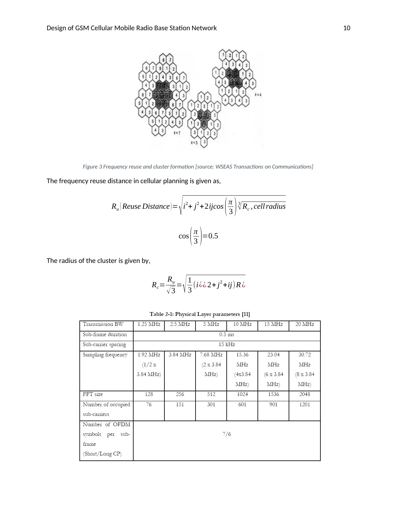
reuse plan yields clustering of cells. Clusters are attributed to the number of cells that are contained
within a given cluster and as a result, the distance from one cluster to another can be used to
determine proper frequency reuse.
⊘ This is a preview!⊘
Do you want full access?
Subscribe today to unlock all pages.

Trusted by 1+ million students worldwide
Design of GSM Cellular Mobile Radio Base Station Network 10
Figure 3 Frequency reuse and cluster formation [source: WSEAS Transactions on Communications]
The frequency reuse distance in cellular planning is given as,
Ru ( Reuse Distance ) = √ i2+ j2 +2ijcos ( π
3 ) 3
√ Rc , cell radius
cos ( π
3 )=0.5
The radius of the cluster is given by,
Rc= Ru
√ 3 = √ 1
3 (i¿¿ 2+ j2 +ij)R ¿
Paraphrase This Document
Need a fresh take? Get an instant paraphrase of this document with our AI Paraphraser
Design of GSM Cellular Mobile Radio Base Station Network 11
4) Tele traffic capacity planning
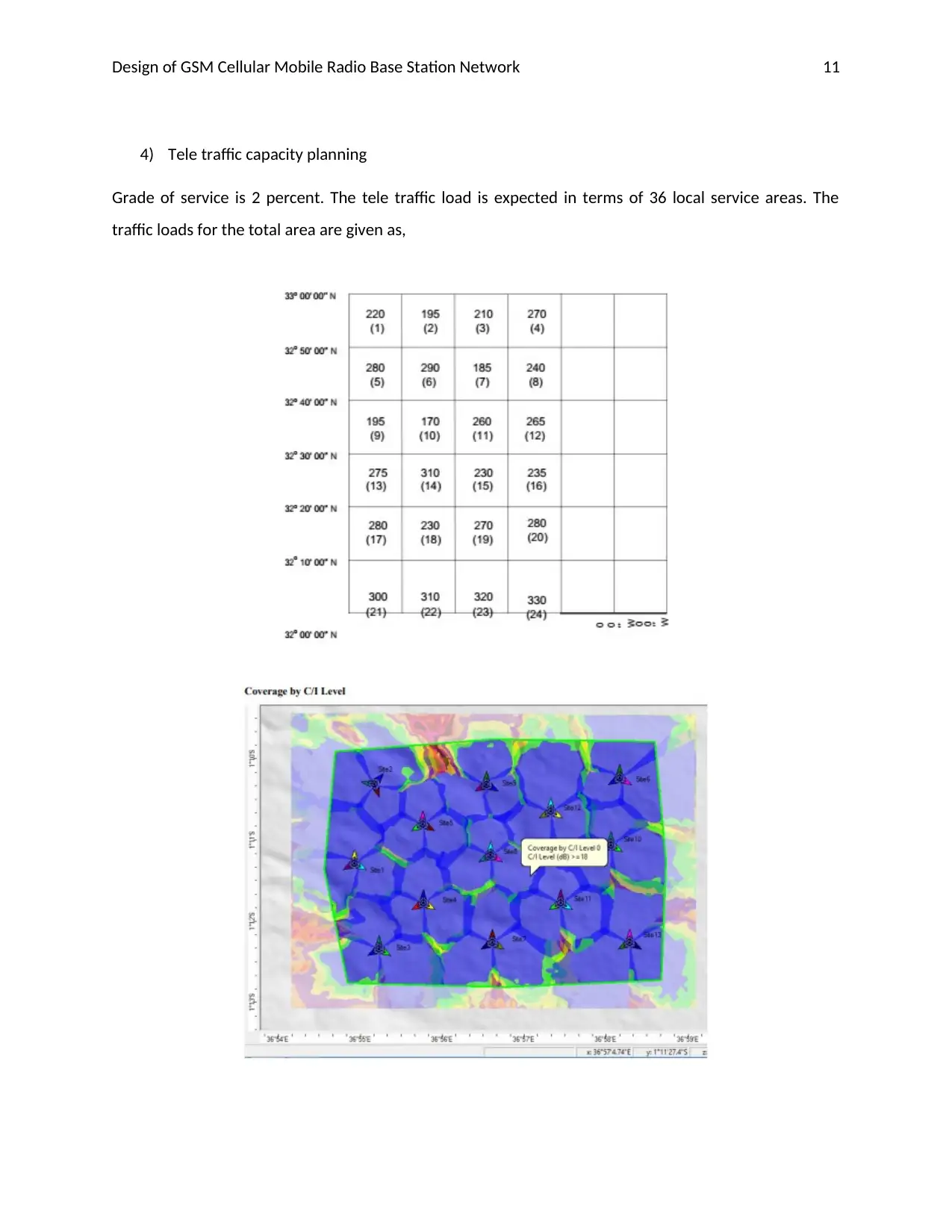
Grade of service is 2 percent. The tele traffic load is expected in terms of 36 local service areas. The
traffic loads for the total area are given as,
4) Tele traffic capacity planning
Grade of service is 2 percent. The tele traffic load is expected in terms of 36 local service areas. The
traffic loads for the total area are given as,
Design of GSM Cellular Mobile Radio Base Station Network 12
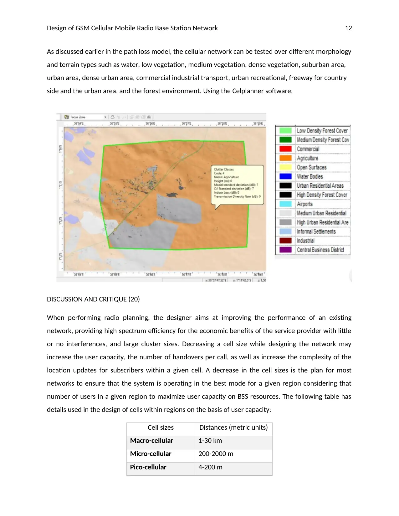
As discussed earlier in the path loss model, the cellular network can be tested over different morphology
and terrain types such as water, low vegetation, medium vegetation, dense vegetation, suburban area,
urban area, dense urban area, commercial industrial transport, urban recreational, freeway for country
side and the urban area, and the forest environment. Using the Celplanner software,
DISCUSSION AND CRITIQUE (20)
When performing radio planning, the designer aims at improving the performance of an existing
network, providing high spectrum efficiency for the economic benefits of the service provider with little
or no interferences, and large cluster sizes. Decreasing a cell size while designing the network may
increase the user capacity, the number of handovers per call, as well as increase the complexity of the
location updates for subscribers within a given cell. A decrease in the cell sizes is the plan for most
networks to ensure that the system is operating in the best mode for a given region considering that
number of users in a given region to maximize user capacity on BSS resources. The following table has
details used in the design of cells within regions on the basis of user capacity:
Cell sizes Distances (metric units)
Macro-cellular 1-30 km
Micro-cellular 200-2000 m
Pico-cellular 4-200 m
⊘ This is a preview!⊘
Do you want full access?
Subscribe today to unlock all pages.

Trusted by 1+ million students worldwide
1 out of 13
Related Documents
Your All-in-One AI-Powered Toolkit for Academic Success.
+13062052269
info@desklib.com
Available 24*7 on WhatsApp / Email
![[object Object]](/_next/static/media/star-bottom.7253800d.svg)
Unlock your academic potential
Copyright © 2020–2026 A2Z Services. All Rights Reserved. Developed and managed by ZUCOL.


