DEN7208/DENM028 Heat Transfer Project: Heat Exchanger Design Analysis
VerifiedAdded on 2023/06/04
|16
|4039
|287
Project
AI Summary
This project focuses on the design and analysis of a heat exchanger for a run-around system, specifically for pre-heating inlet air using discharged air in an air conditioning plant. The report covers various aspects of heat exchanger design, including different types of heat exchangers (direct and indirect contact), flow configurations (parallel, counterflow, and crossflow), and constructional features like concentric tubes and shell-and-tube designs. It delves into heat exchanger analysis, discussing the overall heat transfer coefficient, fouling and scaling effects, and the logarithmic mean temperature difference. The project aims to determine suitable sizes for two finned tube heat exchangers, one for extracting heat from outgoing air and the other for preheating incoming air, considering a total heat transfer of 10 kW. The document emphasizes the importance of assumptions made during the analysis, such as constant flow conditions and negligible heat dissipation to the surroundings.
Design of Heat Exchanger
Submitted
By
Submitted
By
Paraphrase This Document
Need a fresh take? Get an instant paraphrase of this document with our AI Paraphraser
Contents
Introduction.................................................................................................................................................3
Design and constructional features.............................................................................................................6
Heat Exchanger Analysis..............................................................................................................................7
Overall heat transfer coefficient..................................................................................................................8
Fouling or Scaling.........................................................................................................................................9
Logarithmic mean temperature difference...............................................................................................11
References.................................................................................................................................................14

⊘ This is a preview!⊘
Do you want full access?
Subscribe today to unlock all pages.
Trusted by 1+ million students worldwide
Aim/Objective:
In this study design calculation for the installation of the run around system which will pre-heat the inlet
air utilizing the discharged air. This system includes a heat exchanger so a design of heat exchanger
required for this system will also be done and explained with appropriate diagrams and graphs if needed.
Introduction
A heat exchanger is a equipment which enables movement of energy from a hot fluid to a cold fluid. The
transfer occurs at maximum rate with minimal expense and investment. Each fluid temperature varies as
it moves across the exchangers. Thereby the temperature of the partition wall also varies along the length
of the heat exchanger. On the basis of a type of heat exchange process, design and specifications,
corresponding direction of fluid motion and physiological state of fluids, heat exchangers can be
categorized in many ways (Furman and Sahinidis 2002).
1. Type of heat exchange process:
On the basis of heat exchange process heat exchangers can be classified as
Direct contact heat exchangers.
Indirect contact heat exchangers.
Direct contact heat exchangers
In this type of heat exchangers, heat is exchanged by directly mixing of hot and cold fluids and
the transfer of mass and heat takes place. Assumptions are made such that where mixing of such fluidsare
harmless and desirable. The following assumptions are made while mixing of such fluids (Shah and
Sekulic 2003).
1. The overall coefficient of heat transfer should not vary.
2. The conditions of flow must be constant.
3. The heat exchanger is to be considered as insulated thereby it does not dissipate heat to
the surroundings.
4. It should be considered that no change of phase occurs during heat transfer.
5. Assume that the specific heats and the mass flow rate of both hot and cold fluids are not
vary.
The construction of a direct heat exchanger is such that the steam combines with cold water where it
gives its latent heat energy to the water and then condenses. The hot water and other gases which are not
condensed leave the container
Paraphrase This Document
Need a fresh take? Get an instant paraphrase of this document with our AI Paraphraser
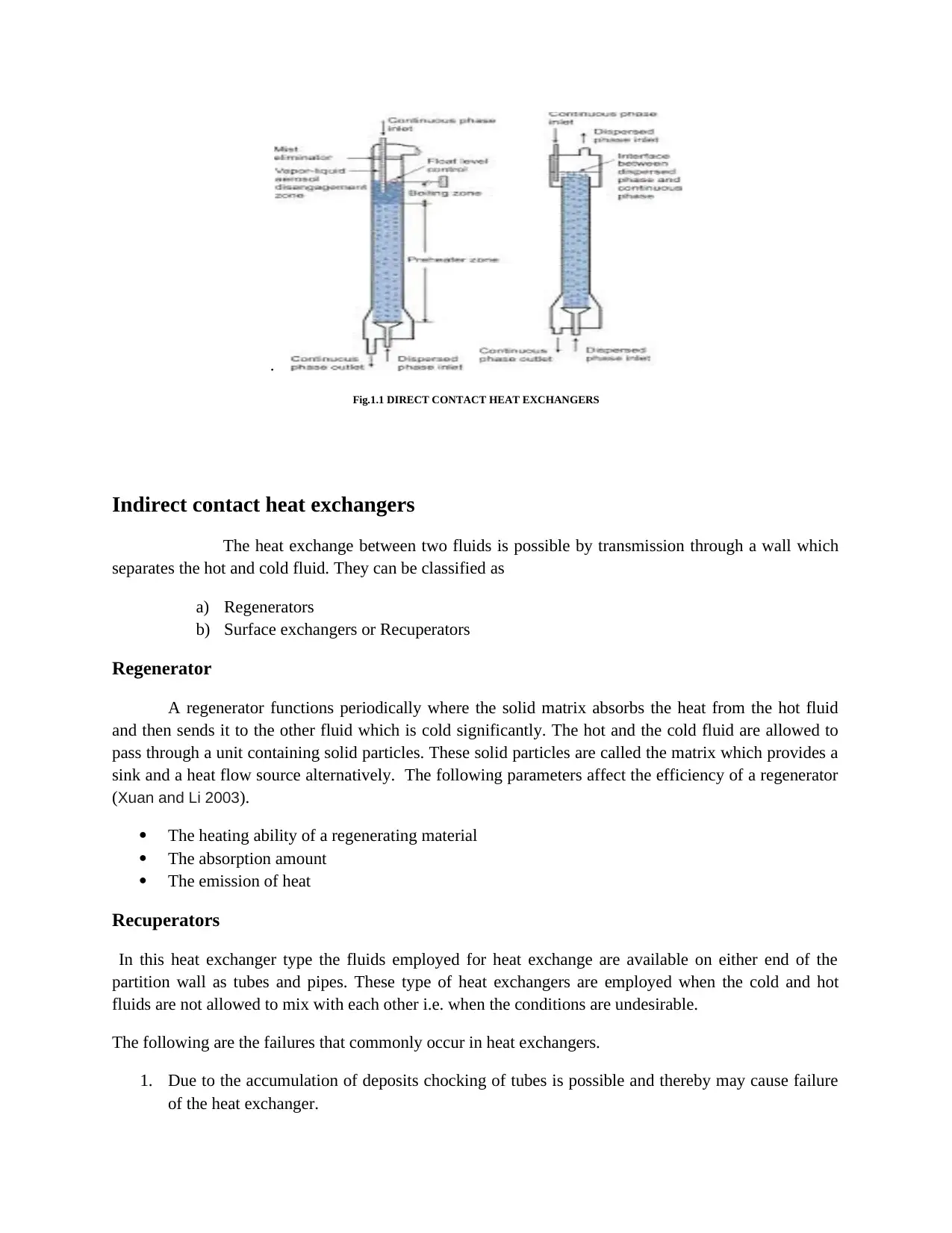
.
Fig.1.1 DIRECT CONTACT HEAT EXCHANGERS
Indirect contact heat exchangers
The heat exchange between two fluids is possible by transmission through a wall which
separates the hot and cold fluid. They can be classified as
a) Regenerators
b) Surface exchangers or Recuperators
Regenerator
A regenerator functions periodically where the solid matrix absorbs the heat from the hot fluid
and then sends it to the other fluid which is cold significantly. The hot and the cold fluid are allowed to
pass through a unit containing solid particles. These solid particles are called the matrix which provides a
sink and a heat flow source alternatively. The following parameters affect the efficiency of a regenerator
(Xuan and Li 2003).
The heating ability of a regenerating material
The absorption amount
The emission of heat
Recuperators
In this heat exchanger type the fluids employed for heat exchange are available on either end of the
partition wall as tubes and pipes. These type of heat exchangers are employed when the cold and hot
fluids are not allowed to mix with each other i.e. when the conditions are undesirable.
The following are the failures that commonly occur in heat exchangers.
1. Due to the accumulation of deposits chocking of tubes is possible and thereby may cause failure
of the heat exchanger.
2. Heat exchanger might fail when there is an excessive transfer of heat.
3. Failure may arise if the pump pressure is increased throughout.
4. If the temperature of the fluids is either extremely hot or extremely cold, this may lead to failure
of the heat exchanger.
5. Lack of control over the heat exchanger may cause failure.
6. If the temperature exceeds the safe design limit failure may occur.
7. Radiations from refractory surfaces may result in failure.
8. Improper heating throughout the circumference of the exchanger may result in failure.
The direction of Fluid flow
On the basis of the direction of fluid flow, the heat exchangers can be classified as follows
Parallel flow on the unidirectional flow
Counterflow
Crossflow
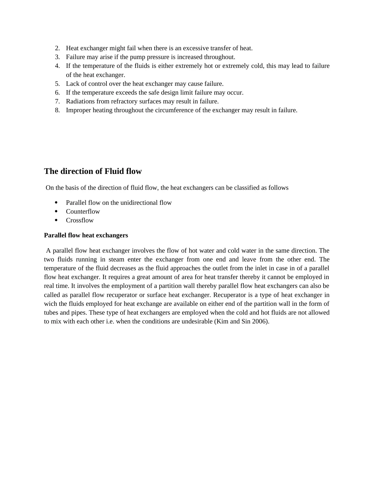
Parallel flow heat exchangers
A parallel flow heat exchanger involves the flow of hot water and cold water in the same direction. The
two fluids running in steam enter the exchanger from one end and leave from the other end. The
temperature of the fluid decreases as the fluid approaches the outlet from the inlet in case in of a parallel
flow heat exchanger. It requires a great amount of area for heat transfer thereby it cannot be employed in
real time. It involves the employment of a partition wall thereby parallel flow heat exchangers can also be
called as parallel flow recuperator or surface heat exchanger. Recuperator is a type of heat exchanger in
wich the fluids employed for heat exchange are available on either end of the partition wall in the form of
tubes and pipes. These type of heat exchangers are employed when the cold and hot fluids are not allowed
to mix with each other i.e. when the conditions are undesirable (Kim and Sin 2006).
3. Failure may arise if the pump pressure is increased throughout.
4. If the temperature of the fluids is either extremely hot or extremely cold, this may lead to failure
of the heat exchanger.
5. Lack of control over the heat exchanger may cause failure.
6. If the temperature exceeds the safe design limit failure may occur.
7. Radiations from refractory surfaces may result in failure.
8. Improper heating throughout the circumference of the exchanger may result in failure.
The direction of Fluid flow
On the basis of the direction of fluid flow, the heat exchangers can be classified as follows
Parallel flow on the unidirectional flow
Counterflow
Crossflow
Parallel flow heat exchangers
A parallel flow heat exchanger involves the flow of hot water and cold water in the same direction. The
two fluids running in steam enter the exchanger from one end and leave from the other end. The
temperature of the fluid decreases as the fluid approaches the outlet from the inlet in case in of a parallel
flow heat exchanger. It requires a great amount of area for heat transfer thereby it cannot be employed in
real time. It involves the employment of a partition wall thereby parallel flow heat exchangers can also be
called as parallel flow recuperator or surface heat exchanger. Recuperator is a type of heat exchanger in
wich the fluids employed for heat exchange are available on either end of the partition wall in the form of
tubes and pipes. These type of heat exchangers are employed when the cold and hot fluids are not allowed
to mix with each other i.e. when the conditions are undesirable (Kim and Sin 2006).
⊘ This is a preview!⊘
Do you want full access?
Subscribe today to unlock all pages.
Trusted by 1+ million students worldwide
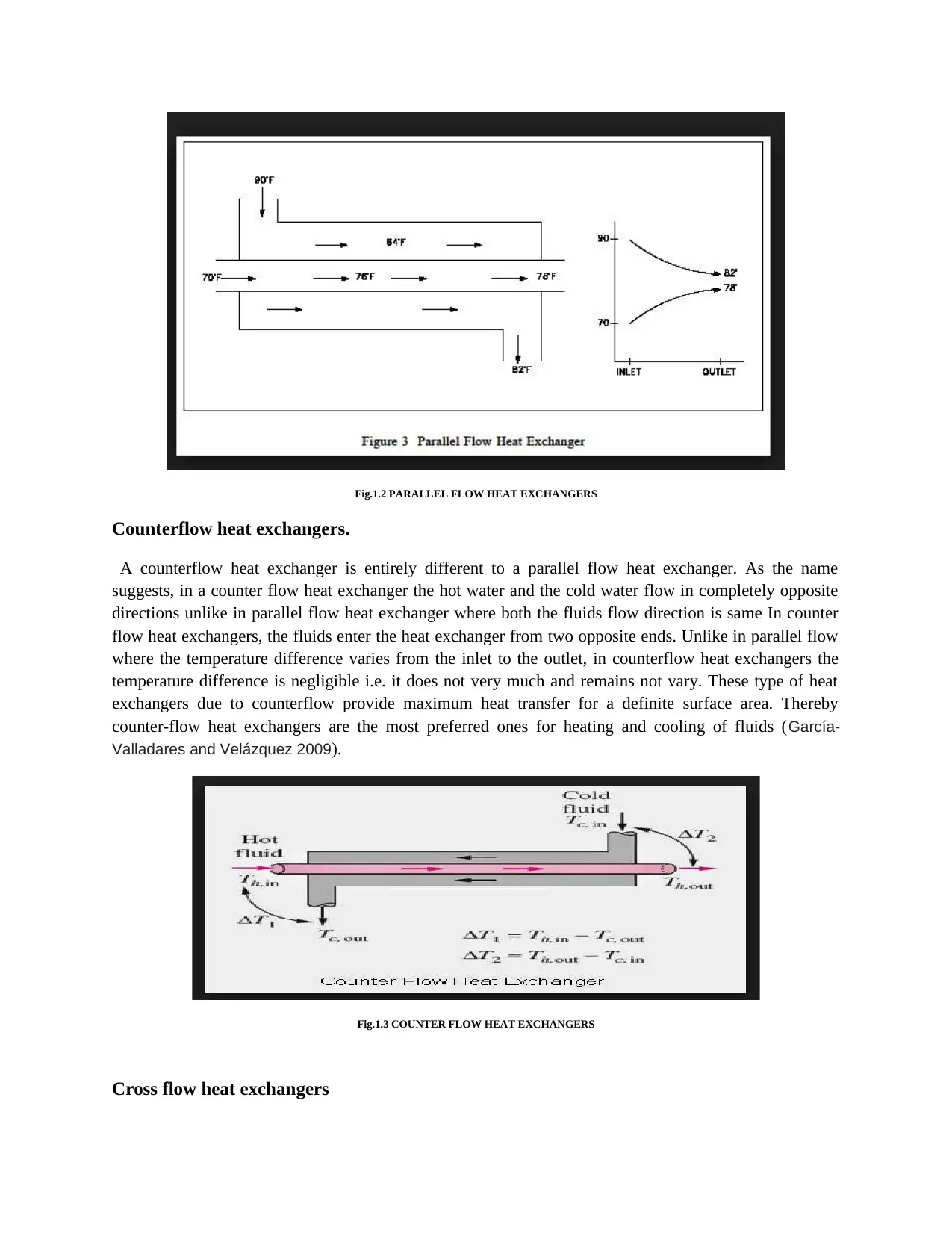
Fig.1.2 PARALLEL FLOW HEAT EXCHANGERS
Counterflow heat exchangers.
A counterflow heat exchanger is entirely different to a parallel flow heat exchanger. As the name
suggests, in a counter flow heat exchanger the hot water and the cold water flow in completely opposite
directions unlike in parallel flow heat exchanger where both the fluids flow direction is same In counter
flow heat exchangers, the fluids enter the heat exchanger from two opposite ends. Unlike in parallel flow
where the temperature difference varies from the inlet to the outlet, in counterflow heat exchangers the
temperature difference is negligible i.e. it does not very much and remains not vary. These type of heat
exchangers due to counterflow provide maximum heat transfer for a definite surface area. Thereby
counter-flow heat exchangers are the most preferred ones for heating and cooling of fluids (García-
Valladares and Velázquez 2009).
Fig.1.3 COUNTER FLOW HEAT EXCHANGERS
Cross flow heat exchangers
Paraphrase This Document
Need a fresh take? Get an instant paraphrase of this document with our AI Paraphraser
Cross flow heat exchangers include the exchange of heat between hot and cold fluids by crossing each
other in space mostly perpendicular to each other i.e. at right angles. The temperature of the fluid remains
uniform throughout but the flow direction only varies.
Design and constructional features
Heat exchangers can be classified as:
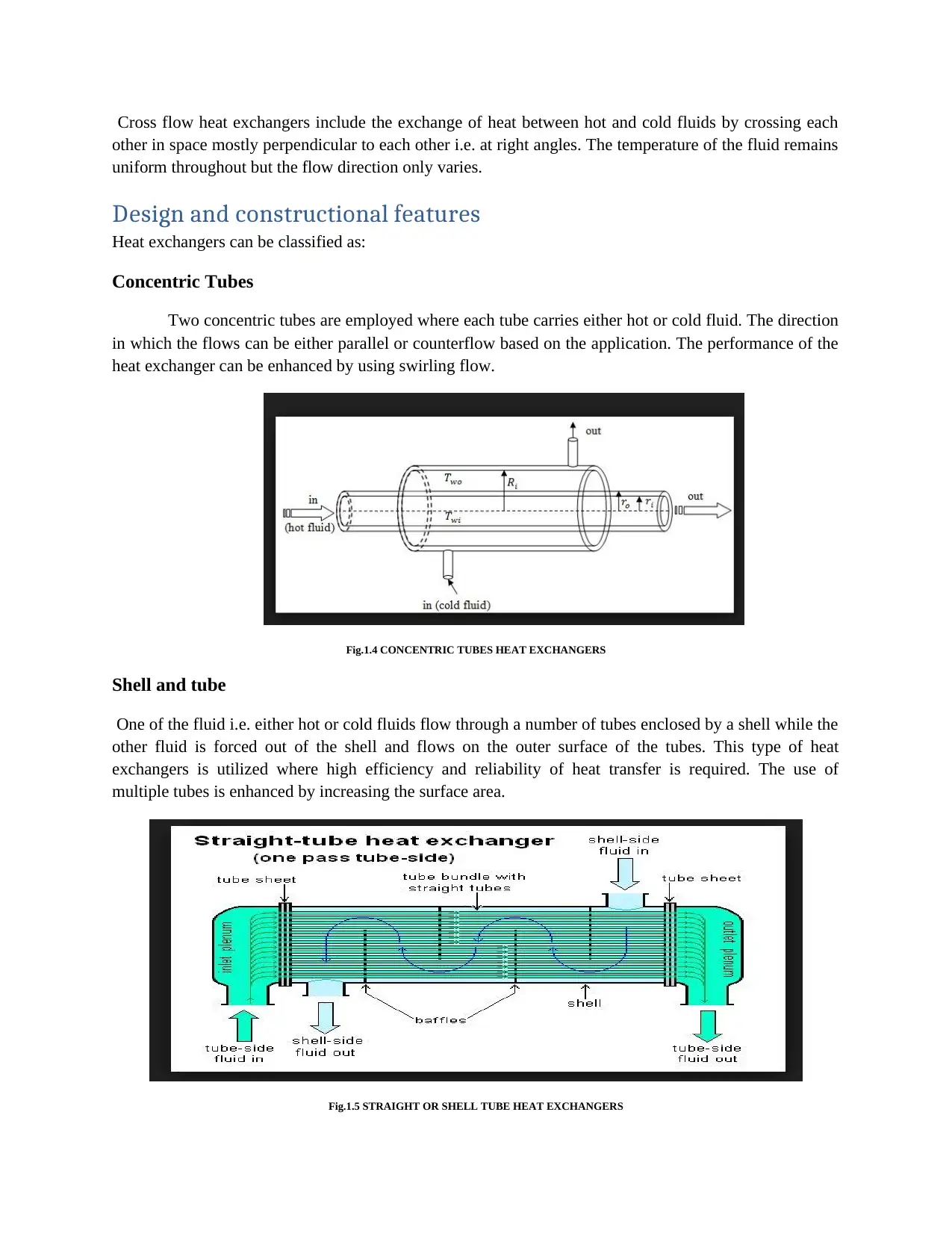
Concentric Tubes
Two concentric tubes are employed where each tube carries either hot or cold fluid. The direction
in which the flows can be either parallel or counterflow based on the application. The performance of the
heat exchanger can be enhanced by using swirling flow.
Fig.1.4 CONCENTRIC TUBES HEAT EXCHANGERS
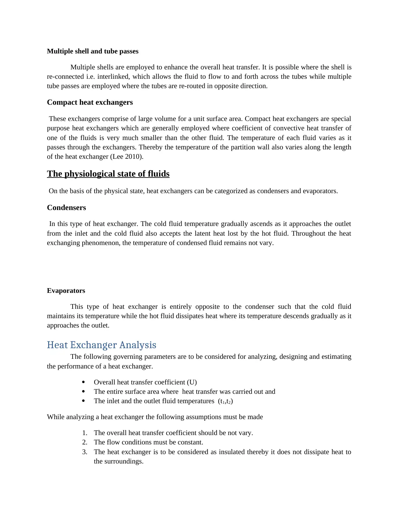
Shell and tube
One of the fluid i.e. either hot or cold fluids flow through a number of tubes enclosed by a shell while the
other fluid is forced out of the shell and flows on the outer surface of the tubes. This type of heat
exchangers is utilized where high efficiency and reliability of heat transfer is required. The use of
multiple tubes is enhanced by increasing the surface area.
Fig.1.5 STRAIGHT OR SHELL TUBE HEAT EXCHANGERS
other in space mostly perpendicular to each other i.e. at right angles. The temperature of the fluid remains
uniform throughout but the flow direction only varies.
Design and constructional features
Heat exchangers can be classified as:
Concentric Tubes
Two concentric tubes are employed where each tube carries either hot or cold fluid. The direction
in which the flows can be either parallel or counterflow based on the application. The performance of the
heat exchanger can be enhanced by using swirling flow.
Fig.1.4 CONCENTRIC TUBES HEAT EXCHANGERS
Shell and tube
One of the fluid i.e. either hot or cold fluids flow through a number of tubes enclosed by a shell while the
other fluid is forced out of the shell and flows on the outer surface of the tubes. This type of heat
exchangers is utilized where high efficiency and reliability of heat transfer is required. The use of
multiple tubes is enhanced by increasing the surface area.
Fig.1.5 STRAIGHT OR SHELL TUBE HEAT EXCHANGERS
Multiple shell and tube passes
Multiple shells are employed to enhance the overall heat transfer. It is possible where the shell is
re-connected i.e. interlinked, which allows the fluid to flow to and forth across the tubes while multiple
tube passes are employed where the tubes are re-routed in opposite direction.
Compact heat exchangers
These exchangers comprise of large volume for a unit surface area. Compact heat exchangers are special
purpose heat exchangers which are generally employed where coefficient of convective heat transfer of
one of the fluids is very much smaller than the other fluid. The temperature of each fluid varies as it
passes through the exchangers. Thereby the temperature of the partition wall also varies along the length
of the heat exchanger (Lee 2010).
The physiological state of fluids
On the basis of the physical state, heat exchangers can be categorized as condensers and evaporators.
Condensers
In this type of heat exchanger. The cold fluid temperature gradually ascends as it approaches the outlet
from the inlet and the cold fluid also accepts the latent heat lost by the hot fluid. Throughout the heat
exchanging phenomenon, the temperature of condensed fluid remains not vary.
Evaporators
This type of heat exchanger is entirely opposite to the condenser such that the cold fluid
maintains its temperature while the hot fluid dissipates heat where its temperature descends gradually as it
approaches the outlet.
Heat Exchanger Analysis
The following governing parameters are to be considered for analyzing, designing and estimating
the performance of a heat exchanger.
Overall heat transfer coefficient (U)
The entire surface area where heat transfer was carried out and
The inlet and the outlet fluid temperatures (t1,t2)
While analyzing a heat exchanger the following assumptions must be made
1. The overall heat transfer coefficient should be not vary.
2. The flow conditions must be constant.
3. The heat exchanger is to be considered as insulated thereby it does not dissipate heat to
the surroundings.
⊘ This is a preview!⊘
Do you want full access?
Subscribe today to unlock all pages.
Trusted by 1+ million students worldwide
4. It should be considered that no change of phase occurs during heat transfer.
5. Assume that the specific heats and the mass flow rate of both the fluids i.e. hot and cold
fluids are not vary.
6. If there is any change in potential energy or kinetic energy it is assumed to be negligible.
7. It is assumed that the axial conduction for the tubes employed in a heat exchanger is
considered to be negligible.
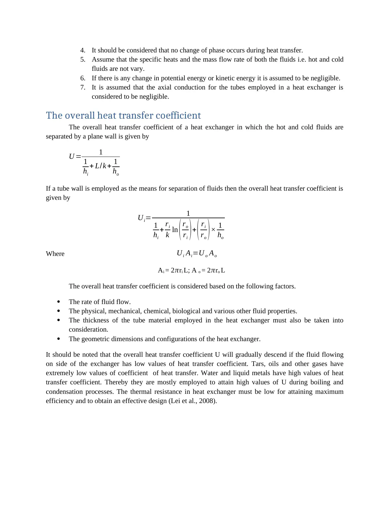
The overall heat transfer coefficient
The overall heat transfer coefficient of a heat exchanger in which the hot and cold fluids are
separated by a plane wall is given by
U = 1
1
hi
+ L/k + 1
ho
If a tube wall is employed as the means for separation of fluids then the overall heat transfer coefficient is
given by
Ui= 1
1
hi
+ ri
k ln ( ro
ri )+ ( ri
ro )× 1
ho
Where Ui Ai=U o Ao
Ai = 2 πri L; A o = 2 πro L
The overall heat transfer coefficient is considered based on the following factors.
The rate of fluid flow.
The physical, mechanical, chemical, biological and various other fluid properties.
The thickness of the tube material employed in the heat exchanger must also be taken into
consideration.
The geometric dimensions and configurations of the heat exchanger.
It should be noted that the overall heat transfer coefficient U will gradually descend if the fluid flowing
on side of the exchanger has low values of heat transfer coefficient. Tars, oils and other gases have
extremely low values of coefficient of heat transfer. Water and liquid metals have high values of heat
transfer coefficient. Thereby they are mostly employed to attain high values of U during boiling and
condensation processes. The thermal resistance in heat exchanger must be low for attaining maximum
efficiency and to obtain an effective design (Lei et al., 2008).
5. Assume that the specific heats and the mass flow rate of both the fluids i.e. hot and cold
fluids are not vary.
6. If there is any change in potential energy or kinetic energy it is assumed to be negligible.
7. It is assumed that the axial conduction for the tubes employed in a heat exchanger is
considered to be negligible.
The overall heat transfer coefficient
The overall heat transfer coefficient of a heat exchanger in which the hot and cold fluids are
separated by a plane wall is given by
U = 1
1
hi
+ L/k + 1
ho
If a tube wall is employed as the means for separation of fluids then the overall heat transfer coefficient is
given by
Ui= 1
1
hi
+ ri
k ln ( ro
ri )+ ( ri
ro )× 1
ho
Where Ui Ai=U o Ao
Ai = 2 πri L; A o = 2 πro L
The overall heat transfer coefficient is considered based on the following factors.
The rate of fluid flow.
The physical, mechanical, chemical, biological and various other fluid properties.
The thickness of the tube material employed in the heat exchanger must also be taken into
consideration.
The geometric dimensions and configurations of the heat exchanger.
It should be noted that the overall heat transfer coefficient U will gradually descend if the fluid flowing
on side of the exchanger has low values of heat transfer coefficient. Tars, oils and other gases have
extremely low values of coefficient of heat transfer. Water and liquid metals have high values of heat
transfer coefficient. Thereby they are mostly employed to attain high values of U during boiling and
condensation processes. The thermal resistance in heat exchanger must be low for attaining maximum
efficiency and to obtain an effective design (Lei et al., 2008).
Paraphrase This Document
Need a fresh take? Get an instant paraphrase of this document with our AI Paraphraser
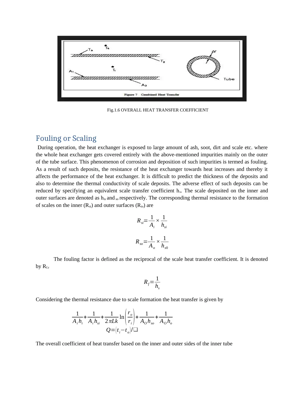
Fig.1.6 OVERALL HEAT TRANSFER COEFFICIENT
Fouling or Scaling
During operation, the heat exchanger is exposed to large amount of ash, soot, dirt and scale etc. where
the whole heat exchanger gets covered entirely with the above-mentioned impurities mainly on the outer
of the tube surface. This phenomenon of corrosion and deposition of such impurities is termed as fouling.
As a result of such deposits, the resistance of the heat exchanger towards heat increases and thereby it
affects the performance of the heat exchanger. It is difficult to predict the thickness of the deposits and
also to determine the thermal conductivity of scale deposits. The adverse effect of such deposits can be
reduced by specifying an equivalent scale transfer coefficient hs. The scale deposited on the inner and
outer surfaces are denoted as his and so respectively. The corresponding thermal resistance to the formation
of scales on the inner (Rsi) and outer surfaces (Rio) are
Rsi= 1
Ai
× 1
hsi
Rso= 1
Ao
× 1
hs0
The fouling factor is defined as the reciprocal of the scale heat transfer coefficient. It is denoted
by Rf.r
Rf = 1
hs
Considering the thermal resistance due to scale formation the heat transfer is given by
1
Ai hi
+ 1
Ai hsi
+ 1
2 πLk ln ( ro
ri ) + 1
AO hso
+ 1
AO ho
Q= ( ti−to ) /❑
The overall coefficient of heat transfer based on the inner and outer sides of the inner tube
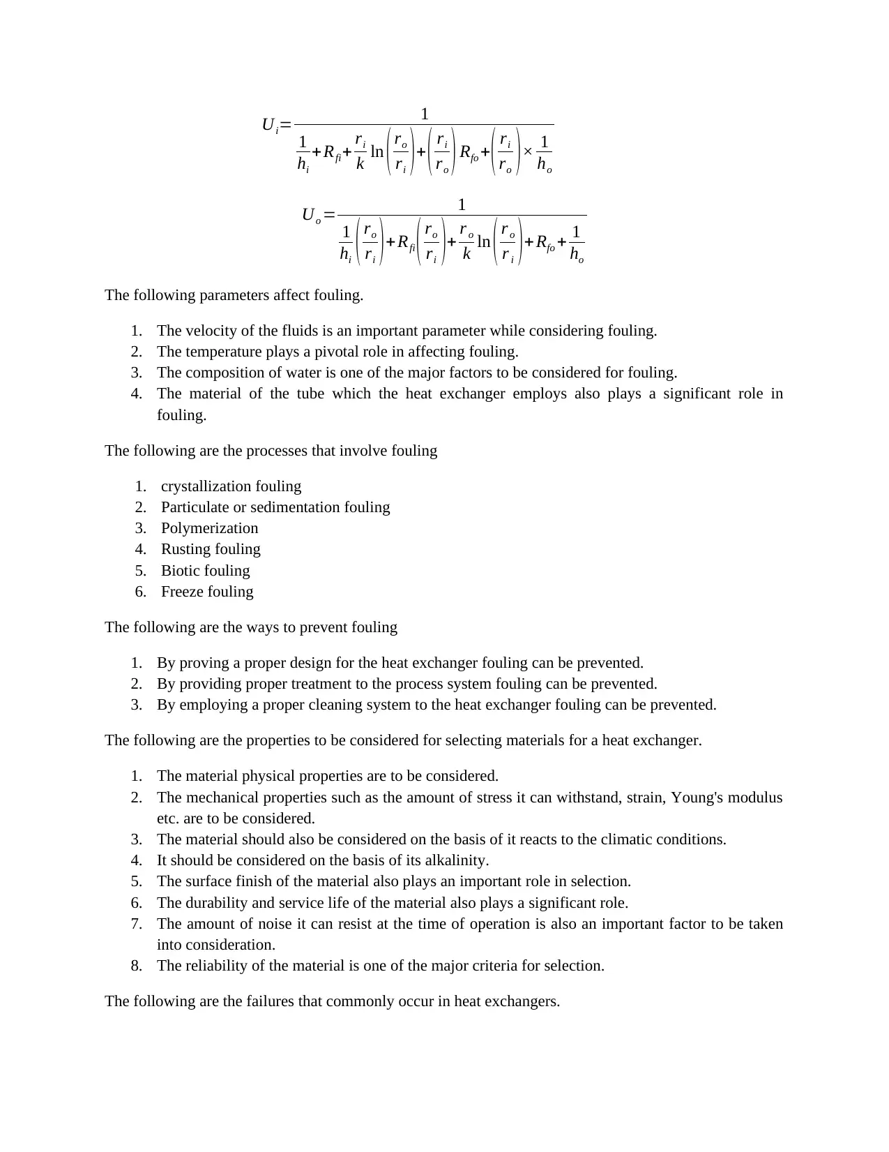
Ui= 1
1
hi
+Rfi+ ri
k ln ( ro
ri )+ ( ri
ro ) Rfo +
( ri
ro )× 1
ho
Uo = 1
1
hi ( ro
ri ) + Rfi ( ro
ri )+ r o
k ln ( r o
r i ) +Rfo + 1
ho
The following parameters affect fouling.
1. The velocity of the fluids is an important parameter while considering fouling.
2. The temperature plays a pivotal role in affecting fouling.
3. The composition of water is one of the major factors to be considered for fouling.
4. The material of the tube which the heat exchanger employs also plays a significant role in
fouling.
The following are the processes that involve fouling
1. crystallization fouling
2. Particulate or sedimentation fouling
3. Polymerization
4. Rusting fouling
5. Biotic fouling
6. Freeze fouling
The following are the ways to prevent fouling
1. By proving a proper design for the heat exchanger fouling can be prevented.
2. By providing proper treatment to the process system fouling can be prevented.
3. By employing a proper cleaning system to the heat exchanger fouling can be prevented.
The following are the properties to be considered for selecting materials for a heat exchanger.
1. The material physical properties are to be considered.
2. The mechanical properties such as the amount of stress it can withstand, strain, Young's modulus
etc. are to be considered.
3. The material should also be considered on the basis of it reacts to the climatic conditions.
4. It should be considered on the basis of its alkalinity.
5. The surface finish of the material also plays an important role in selection.
6. The durability and service life of the material also plays a significant role.
7. The amount of noise it can resist at the time of operation is also an important factor to be taken
into consideration.
8. The reliability of the material is one of the major criteria for selection.
The following are the failures that commonly occur in heat exchangers.
1
hi
+Rfi+ ri
k ln ( ro
ri )+ ( ri
ro ) Rfo +
( ri
ro )× 1
ho
Uo = 1
1
hi ( ro
ri ) + Rfi ( ro
ri )+ r o
k ln ( r o
r i ) +Rfo + 1
ho
The following parameters affect fouling.
1. The velocity of the fluids is an important parameter while considering fouling.
2. The temperature plays a pivotal role in affecting fouling.
3. The composition of water is one of the major factors to be considered for fouling.
4. The material of the tube which the heat exchanger employs also plays a significant role in
fouling.
The following are the processes that involve fouling
1. crystallization fouling
2. Particulate or sedimentation fouling
3. Polymerization
4. Rusting fouling
5. Biotic fouling
6. Freeze fouling
The following are the ways to prevent fouling
1. By proving a proper design for the heat exchanger fouling can be prevented.
2. By providing proper treatment to the process system fouling can be prevented.
3. By employing a proper cleaning system to the heat exchanger fouling can be prevented.
The following are the properties to be considered for selecting materials for a heat exchanger.
1. The material physical properties are to be considered.
2. The mechanical properties such as the amount of stress it can withstand, strain, Young's modulus
etc. are to be considered.
3. The material should also be considered on the basis of it reacts to the climatic conditions.
4. It should be considered on the basis of its alkalinity.
5. The surface finish of the material also plays an important role in selection.
6. The durability and service life of the material also plays a significant role.
7. The amount of noise it can resist at the time of operation is also an important factor to be taken
into consideration.
8. The reliability of the material is one of the major criteria for selection.
The following are the failures that commonly occur in heat exchangers.
⊘ This is a preview!⊘
Do you want full access?
Subscribe today to unlock all pages.
Trusted by 1+ million students worldwide
1 out of 16
Related Documents


Your All-in-One AI-Powered Toolkit for Academic Success.
+13062052269
info@desklib.com
Available 24*7 on WhatsApp / Email
![[object Object]](/_next/static/media/star-bottom.7253800d.svg)
Unlock your academic potential
Copyright © 2020–2026 A2Z Services. All Rights Reserved. Developed and managed by ZUCOL.