Design of Heat Exchanger: Tube Passes, Triangular Pitch, and Fluid Properties

Verified

Added on  2023/06/15

|10
|1391
|60
AI Summary
This article discusses the impact of tube passes and triangular pitch on heat exchanger design, as well as the effects of fluid properties on heat transfer. It includes calculations and analysis of inner diameter, tube pitch, baffle spacing, tube clearance, layout of tubes, number of tubes, cross flow area, velocity inside tube, Reynolds number, friction factor, Nusselt number, heat transfer coefficient, total heat transfer areas, overall heat transfer coefficient, heat capacities, number of transfer units, effectiveness of heat exchanger, and pressure drop. It also explores the effects of doubling the specific heat capacity of the primary cooling liquid on the size of the heat exchanger.

Contribute Materials

Your contribution can guide someone’s learning journey. Share your documents today.
Document Page
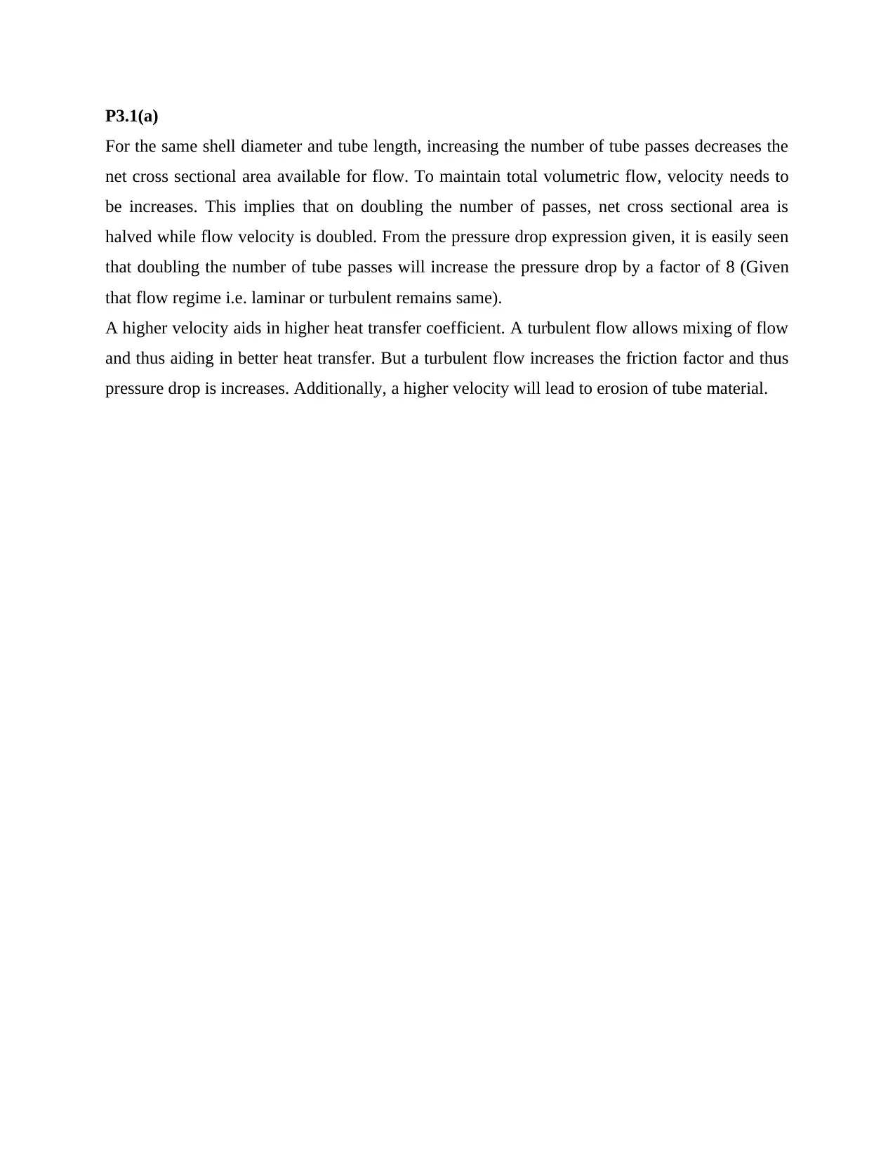
P3.1(a)
For the same shell diameter and tube length, increasing the number of tube passes decreases the
net cross sectional area available for flow. To maintain total volumetric flow, velocity needs to
be increases. This implies that on doubling the number of passes, net cross sectional area is
halved while flow velocity is doubled. From the pressure drop expression given, it is easily seen
that doubling the number of tube passes will increase the pressure drop by a factor of 8 (Given
that flow regime i.e. laminar or turbulent remains same).
A higher velocity aids in higher heat transfer coefficient. A turbulent flow allows mixing of flow
and thus aiding in better heat transfer. But a turbulent flow increases the friction factor and thus
pressure drop is increases. Additionally, a higher velocity will lead to erosion of tube material.

Secure Best Marks with AI Grader

Need help grading? Try our AI Grader for instant feedback on your assignments.
Document Page
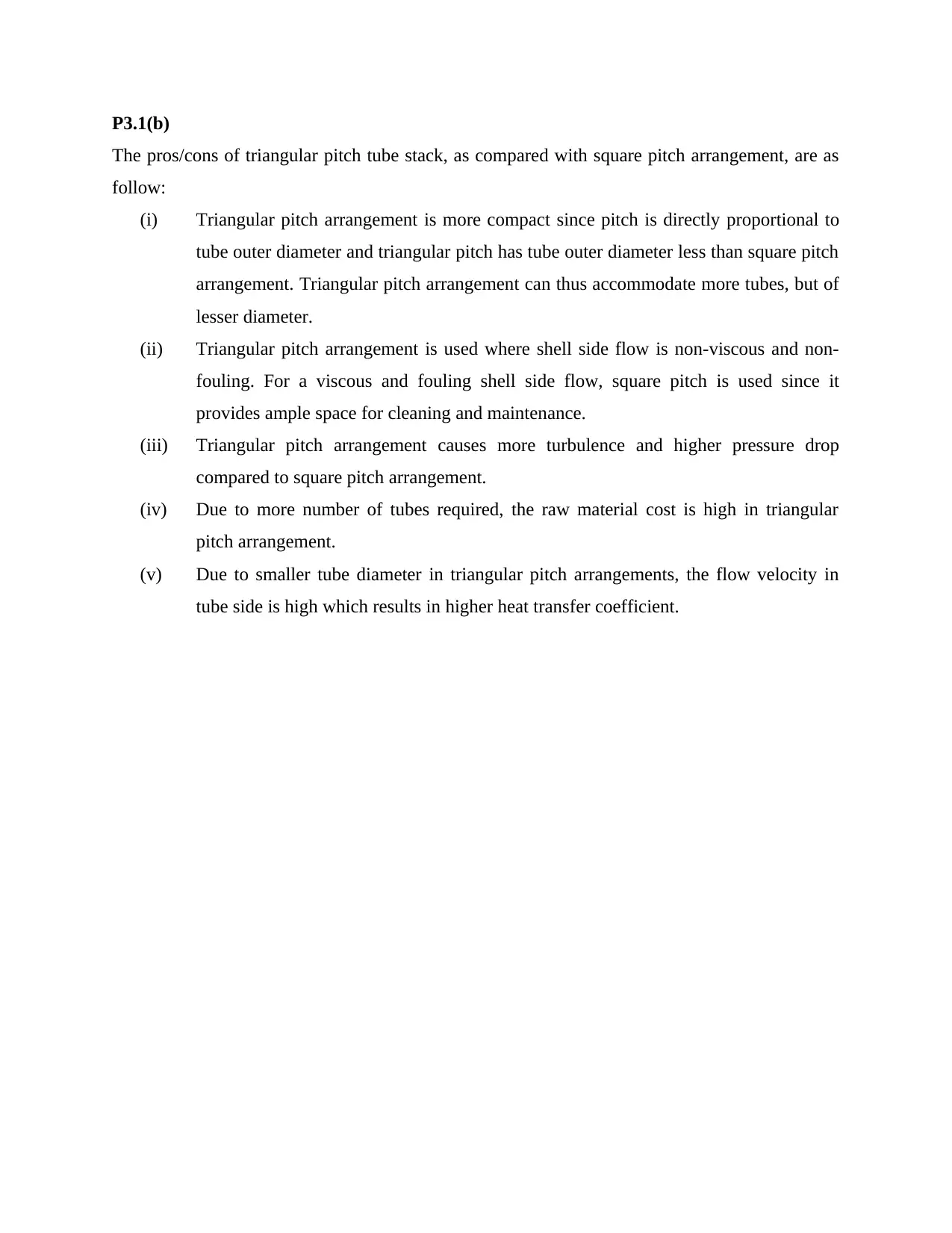
P3.1(b)
The pros/cons of triangular pitch tube stack, as compared with square pitch arrangement, are as
follow:
(i) Triangular pitch arrangement is more compact since pitch is directly proportional to
tube outer diameter and triangular pitch has tube outer diameter less than square pitch
arrangement. Triangular pitch arrangement can thus accommodate more tubes, but of
lesser diameter.
(ii) Triangular pitch arrangement is used where shell side flow is non-viscous and non-
fouling. For a viscous and fouling shell side flow, square pitch is used since it
provides ample space for cleaning and maintenance.
(iii) Triangular pitch arrangement causes more turbulence and higher pressure drop
compared to square pitch arrangement.
(iv) Due to more number of tubes required, the raw material cost is high in triangular
pitch arrangement.
(v) Due to smaller tube diameter in triangular pitch arrangements, the flow velocity in
tube side is high which results in higher heat transfer coefficient.
Document Page
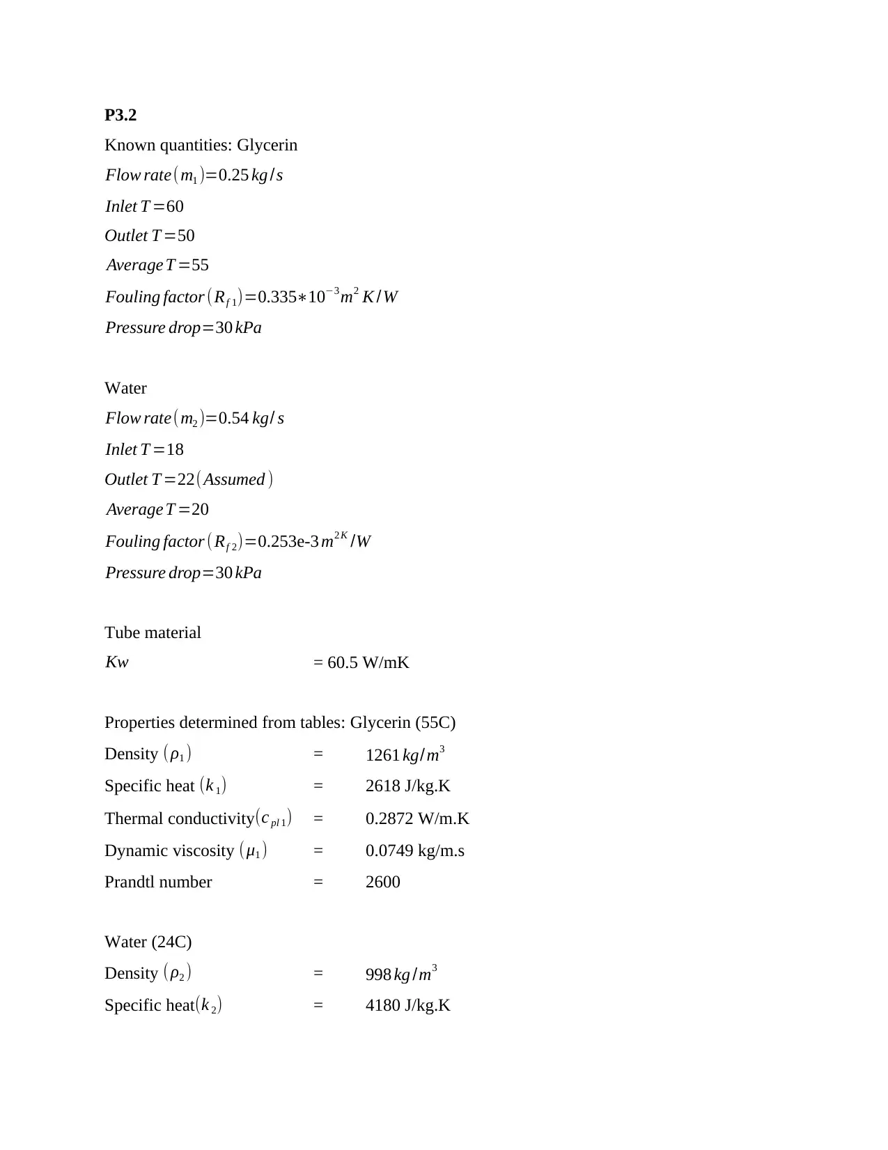
P3.2
Known quantities: Glycerin
Flow rate(m1 )=0.25 kg /s
Inlet T =60
Outlet T =50
Average T =55
Fouling factor (Rf 1)=0.335103 m2 K /W
Pressure drop=30 kPa
Water
Flow rate(m2 )=0.54 kg/ s
Inlet T =18
Outlet T =22(Assumed )
Average T =20
Fouling factor ( Rf 2)=0.253e-3 m2 K /W
Pressure drop=30 kPa
Tube material
Kw = 60.5 W/mK
Properties determined from tables: Glycerin (55C)
Density (ρ1 ) = 1261 kg/m3
Specific heat (k 1) = 2618 J/kg.K
Thermal conductivity (c pl 1) = 0.2872 W/m.K
Dynamic viscosity (μ1 ) = 0.0749 kg/m.s
Prandtl number = 2600
Water (24C)
Density (ρ2 ) = 998 kg /m3
Specific heat(k 2) = 4180 J/kg.K
Document Page
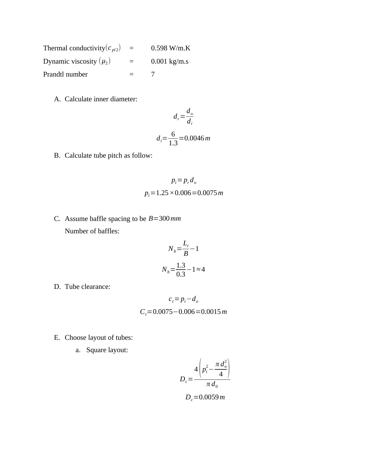
Thermal conductivity (c pl 2) = 0.598 W/m.K
Dynamic viscosity (μ2 ) = 0.001 kg/m.s
Prandtl number = 7
A. Calculate inner diameter:
dr = do
di
di= 6
1.3 =0.0046 m
B. Calculate tube pitch as follow:
pt = pr do
pt =1.25 ×0.006=0.0075 m
C. Assume baffle spacing to be B=300 mm
Number of baffles:
Nb = Lt
B 1
Nb =1.3
0.3 1 4
D. Tube clearance:
ct = pt do
Ct=0.00750.006=0.0015 m
E. Choose layout of tubes:
a. Square layout:
Dc=
4 ( pt
2 π do
2
4 )
π d0
Dc=0.0059 m

Secure Best Marks with AI Grader

Need help grading? Try our AI Grader for instant feedback on your assignments.
Document Page
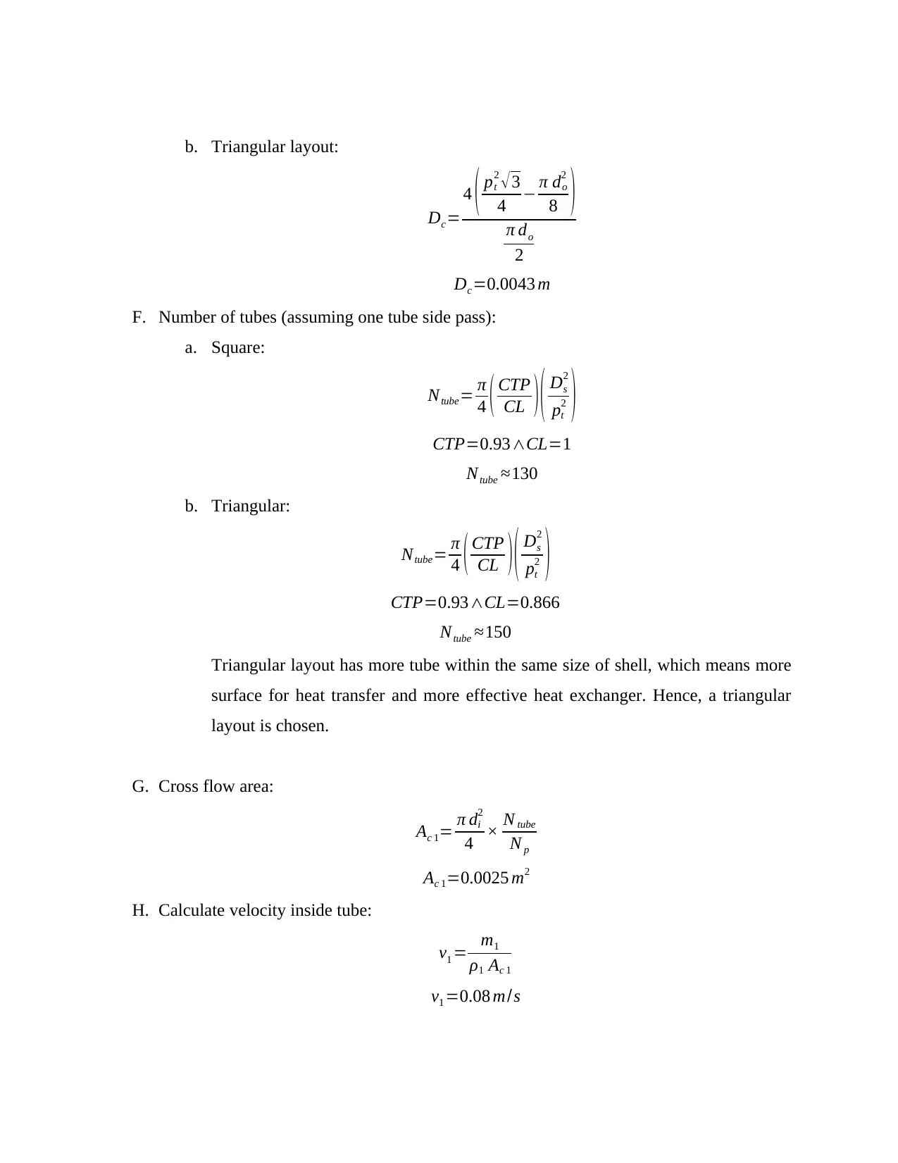
b. Triangular layout:
Dc=
4 ( pt
2 3
4 π do
2
8 )
π do
2
Dc=0.0043 m
F. Number of tubes (assuming one tube side pass):
a. Square:
Ntube= π
4 ( CTP
CL ) ( Ds
2
pt
2 )
CTP=0.93CL=1
Ntube 130
b. Triangular:
Ntube= π
4 ( CTP
CL ) ( Ds
2
pt
2 )
CTP=0.93CL=0.866
Ntube 150
Triangular layout has more tube within the same size of shell, which means more
surface for heat transfer and more effective heat exchanger. Hence, a triangular
layout is chosen.
G. Cross flow area:
Ac 1= π di
2
4 × N tube
N p
Ac 1=0.0025 m2
H. Calculate velocity inside tube:
v1 = m1
ρ1 Ac 1
v1 =0.08 m/s
Document Page
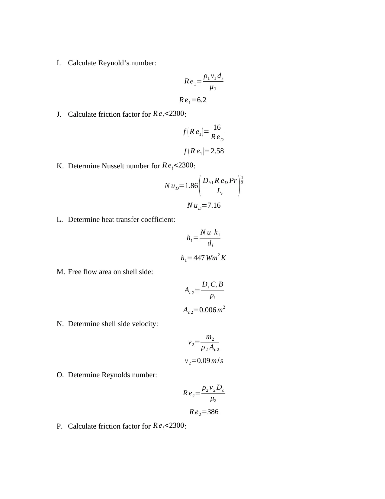
I. Calculate Reynold’s number:
R e1= ρ1 v1 di
μ1
R e1=6.2
J. Calculate friction factor for R e!<2300:
f ( R e1 )= 16
R eD
f ( R e1 ) =2.58
K. Determine Nusselt number for R e!<2300:
N uD=1.86 ( Dh 1 R eD Pr
Lt )1
3
N uD=7.16
L. Determine heat transfer coefficient:
h1= N u1 k1
di
h1=447 Wm2 K
M. Free flow area on shell side:
Ac 2= Ds Ct B
pt
Ac 2=0.006 m2
N. Determine shell side velocity:
v2= m2
ρ2 Ac 2
v2=0.09 m/s
O. Determine Reynolds number:
R e2= ρ2 v2 Dc
μ2
R e2=386
P. Calculate friction factor for R e!<2300:
Document Page
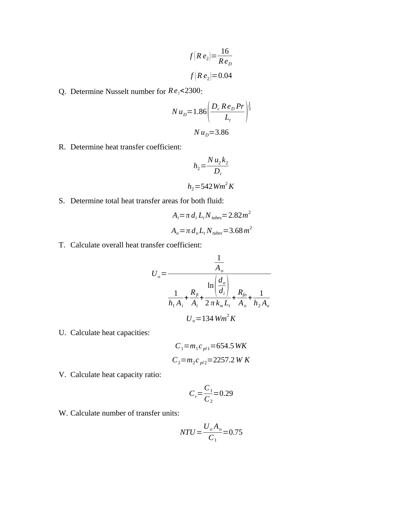
f ( R e2 )= 16
R eD
f ( R e2 )=0.04
Q. Determine Nusselt number for R e!<2300:
N uD=1.86 ( Dc R eD Pr
Lt ) 1
3
N uD=3.86
R. Determine heat transfer coefficient:
h2 = N u2 k2
Dc
h2 =542Wm2 K
S. Determine total heat transfer areas for both fluid:
Ai=π di Lt N tubes=2.82m2
Ao =π do Lt Ntubes=3.68 m2
T. Calculate overall heat transfer coefficient:
Uo =
1
Ao
1
h1 Ai
+ Rfi
Ai
+
ln ( do
di )
2 π kw Lt
+ Rfo
Ao
+ 1
h2 Ao
Uo =134 Wm2 K
U. Calculate heat capacities:
C1=m1 c pl 1=654.5 WK
C2=m2 c pl 2=2257.2 W K
V. Calculate heat capacity ratio:
Cr= C1
C2
=0.29
W. Calculate number of transfer units:
NTU = Uo Ao
C1
=0.75

Paraphrase This Document

Need a fresh take? Get an instant paraphrase of this document with our AI Paraphraser
Document Page
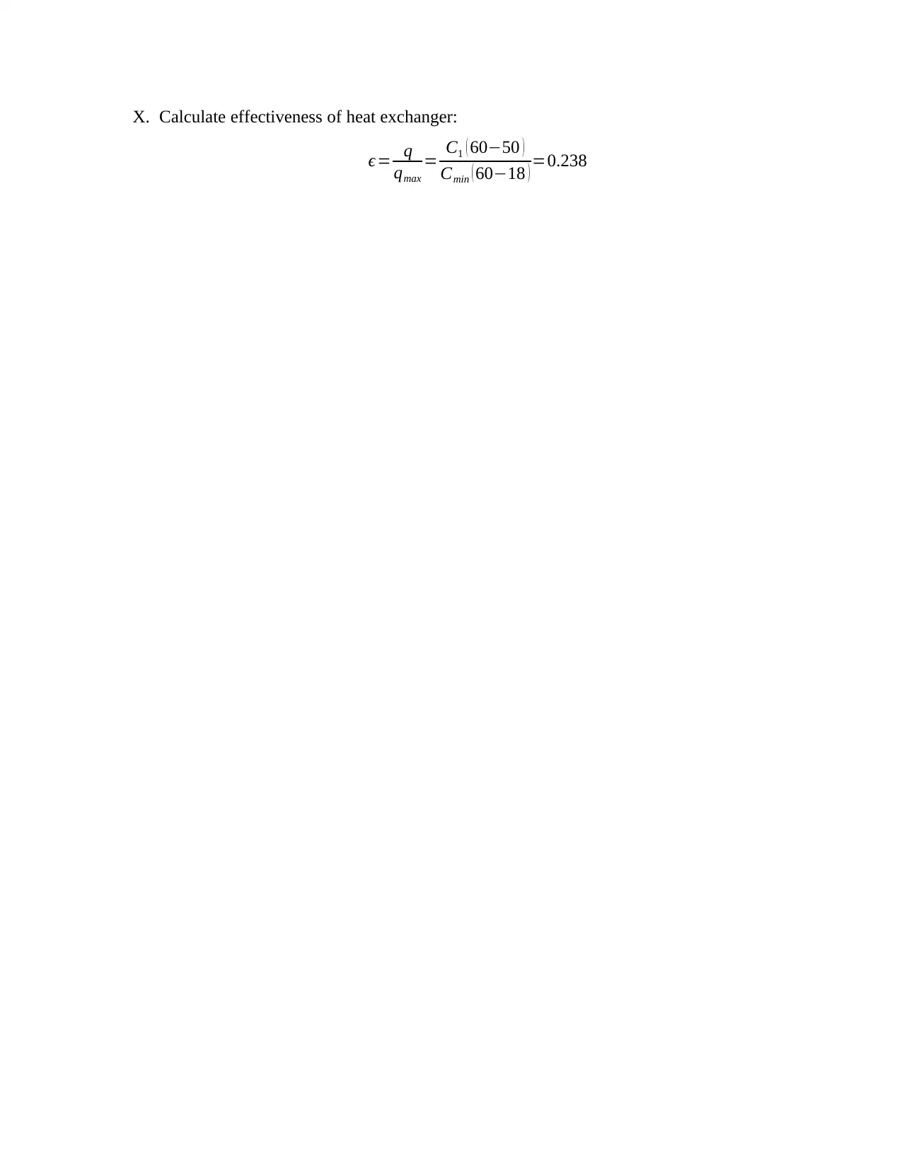
X. Calculate effectiveness of heat exchanger:
ϵ= q
qmax
= C1 ( 6050 )
Cmin ( 6018 ) =0.238
Document Page
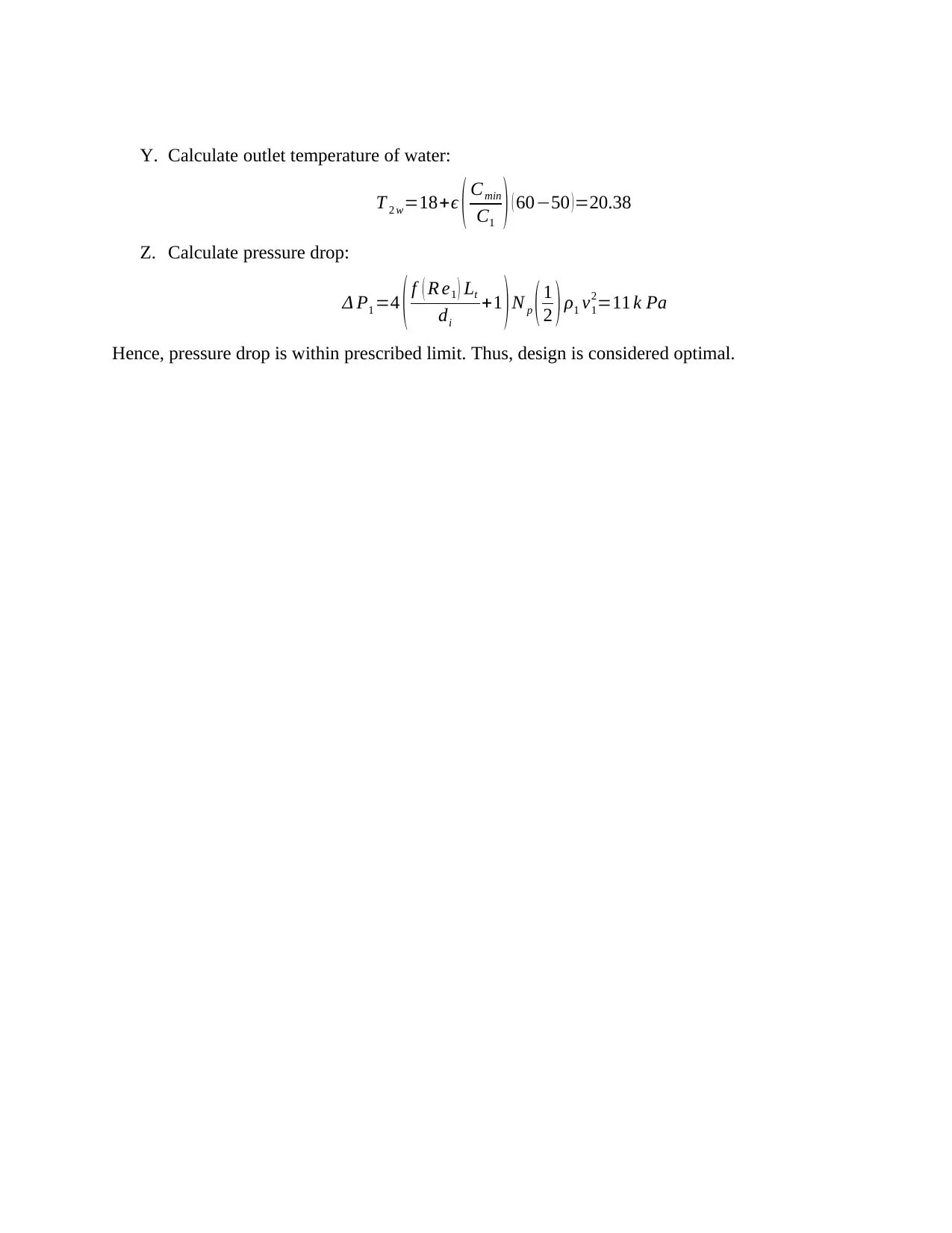
Y. Calculate outlet temperature of water:
T 2 w=18+ϵ ( Cmin
C1 ) ( 6050 )=20.38
Z. Calculate pressure drop:
Δ P1 =4 ( f ( R e1 ) Lt
di
+1 ) N p ( 1
2 ) ρ1 v1
2=11 k Pa
Hence, pressure drop is within prescribed limit. Thus, design is considered optimal.
Document Page
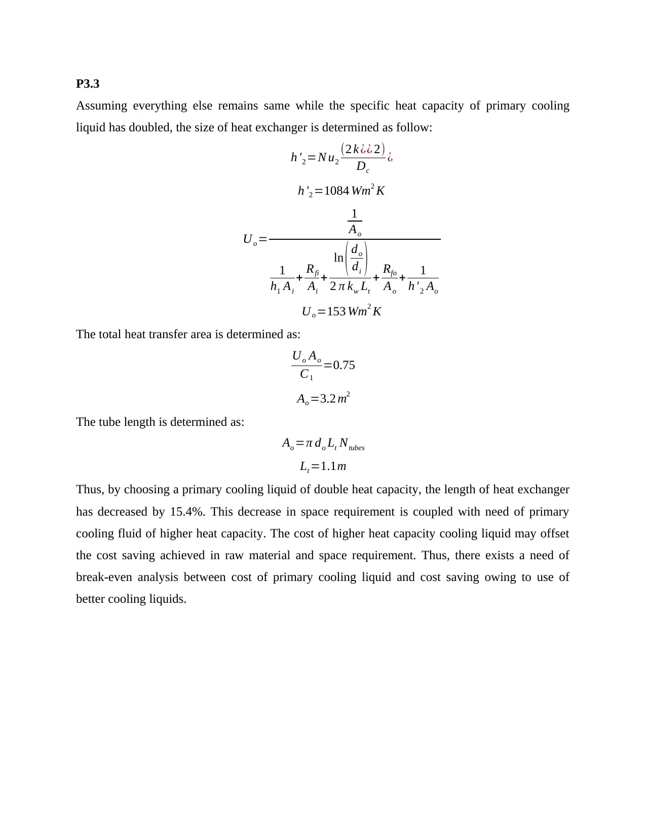
P3.3
Assuming everything else remains same while the specific heat capacity of primary cooling
liquid has doubled, the size of heat exchanger is determined as follow:
h '2 =N u2
(2 k ¿¿ 2)
Dc
¿
h '2 =1084 Wm2 K
Uo =
1
Ao
1
h1 Ai
+ Rfi
Ai
+
ln ( do
di )
2 π kw Lt
+ Rfo
Ao
+ 1
h '2 Ao
Uo =153 Wm2 K
The total heat transfer area is determined as:
Uo Ao
C1
=0.75
Ao =3.2 m2
The tube length is determined as:
Ao =π do Lt Ntubes
Lt =1.1m
Thus, by choosing a primary cooling liquid of double heat capacity, the length of heat exchanger
has decreased by 15.4%. This decrease in space requirement is coupled with need of primary
cooling fluid of higher heat capacity. The cost of higher heat capacity cooling liquid may offset
the cost saving achieved in raw material and space requirement. Thus, there exists a need of
break-even analysis between cost of primary cooling liquid and cost saving owing to use of
better cooling liquids.
1 out of 10
circle_padding
hide_on_mobile
zoom_out_icon
[object Object]

Your All-in-One AI-Powered Toolkit for Academic Success.

Available 24*7 on WhatsApp / Email

[object Object]