EGH 422 Advanced Thermodynamics - Heat Exchanger Performance Report
VerifiedAdded on 2023/06/03
|17
|3672
|50
Report
AI Summary
This lab report details an experiment to calculate heat transfer in four different types of heat exchangers: cross-flow, copper double pipe, aluminum double pipe, and shell and tube. The experiment involves measuring inlet and outlet temperatures of hot and cold fluids to determine the overall heat transfer coefficient, area of heat exchangers, and mean temperature difference. The procedure includes varying flow rates for parallel and counter flow configurations, recording temperature and flow rate measurements, and calculating heat loss/gain and log mean temperature difference (LMTD). The results are presented in tables, showing heat transfer values and LMTD for each heat exchanger type and flow configuration. The report also references formulas and methods for calculating heat transfer and LMTD, providing a comprehensive analysis of heat exchanger performance.

LAB REPORT
REPORT
ON
HEAT EXCHANGER PERFORMANCE
1 | P a g e
REPORT
ON
HEAT EXCHANGER PERFORMANCE
1 | P a g e
Paraphrase This Document
Need a fresh take? Get an instant paraphrase of this document with our AI Paraphraser
LAB REPORT
AIM
The main aim of this experiment is to calculate the amount of heat transfer in four different
types of heat exchangers. For heat transfer calculation, values of overall heat transfer
coefficient, area of heat exchangers, mean temperature difference is required which is
calculated from inlet and outlet temperature of hold and cold fluid measured experimentally .
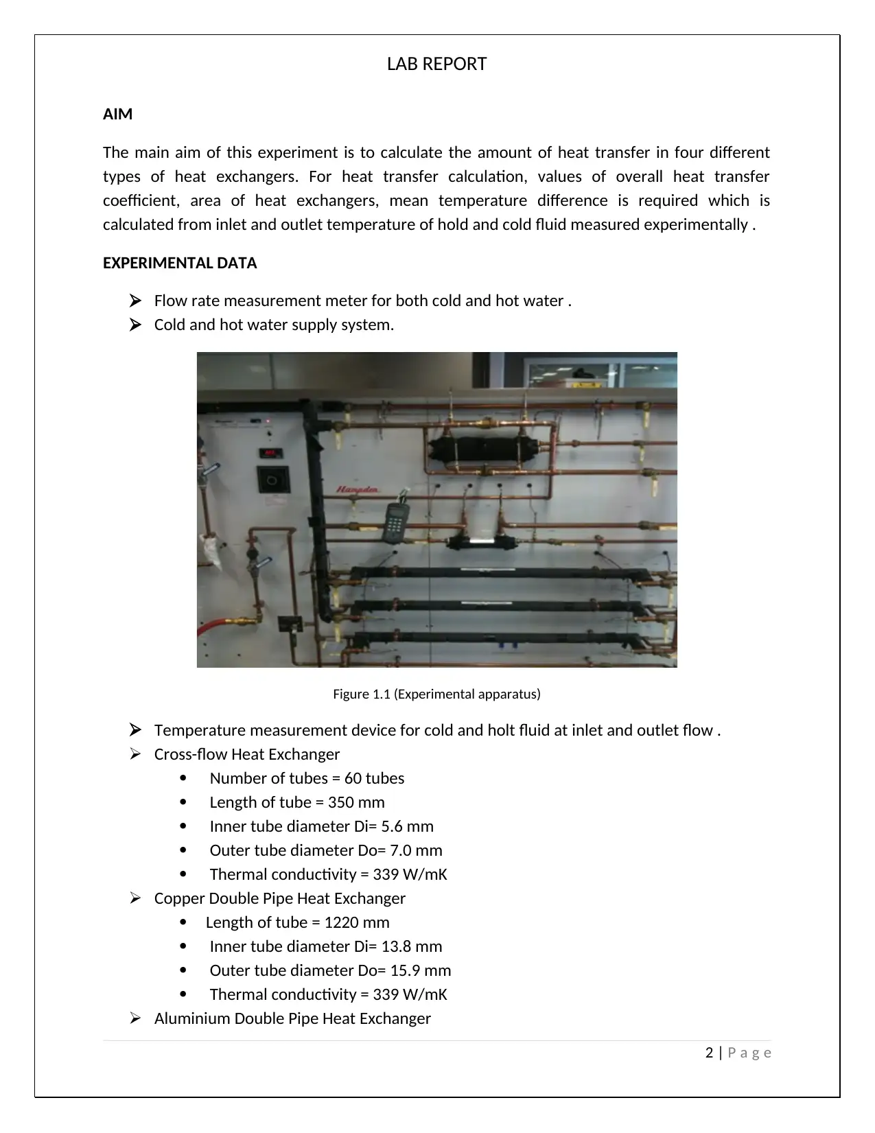
EXPERIMENTAL DATA
Flow rate measurement meter for both cold and hot water .
Cold and hot water supply system.
Figure 1.1 (Experimental apparatus)
Temperature measurement device for cold and holt fluid at inlet and outlet flow .
Cross-flow Heat Exchanger
Number of tubes = 60 tubes
Length of tube = 350 mm
Inner tube diameter Di= 5.6 mm
Outer tube diameter Do= 7.0 mm
Thermal conductivity = 339 W/mK
Copper Double Pipe Heat Exchanger
Length of tube = 1220 mm
Inner tube diameter Di= 13.8 mm
Outer tube diameter Do= 15.9 mm
Thermal conductivity = 339 W/mK
Aluminium Double Pipe Heat Exchanger
2 | P a g e
AIM
The main aim of this experiment is to calculate the amount of heat transfer in four different
types of heat exchangers. For heat transfer calculation, values of overall heat transfer
coefficient, area of heat exchangers, mean temperature difference is required which is
calculated from inlet and outlet temperature of hold and cold fluid measured experimentally .
EXPERIMENTAL DATA
Flow rate measurement meter for both cold and hot water .
Cold and hot water supply system.
Figure 1.1 (Experimental apparatus)
Temperature measurement device for cold and holt fluid at inlet and outlet flow .
Cross-flow Heat Exchanger
Number of tubes = 60 tubes
Length of tube = 350 mm
Inner tube diameter Di= 5.6 mm
Outer tube diameter Do= 7.0 mm
Thermal conductivity = 339 W/mK
Copper Double Pipe Heat Exchanger
Length of tube = 1220 mm
Inner tube diameter Di= 13.8 mm
Outer tube diameter Do= 15.9 mm
Thermal conductivity = 339 W/mK
Aluminium Double Pipe Heat Exchanger
2 | P a g e
LAB REPORT
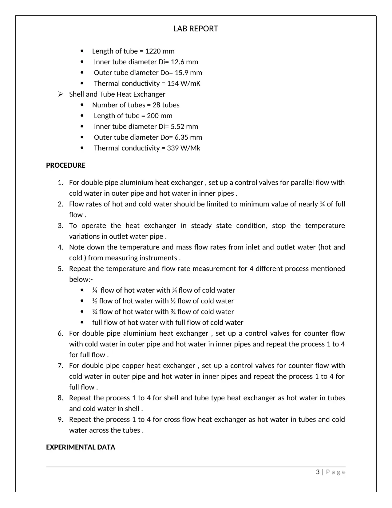
Length of tube = 1220 mm
Inner tube diameter Di= 12.6 mm
Outer tube diameter Do= 15.9 mm
Thermal conductivity = 154 W/mK
Shell and Tube Heat Exchanger
Number of tubes = 28 tubes
Length of tube = 200 mm
Inner tube diameter Di= 5.52 mm
Outer tube diameter Do= 6.35 mm
Thermal conductivity = 339 W/Mk
PROCEDURE
1. For double pipe aluminium heat exchanger , set up a control valves for parallel flow with
cold water in outer pipe and hot water in inner pipes .
2. Flow rates of hot and cold water should be limited to minimum value of nearly ¼ of full
flow .
3. To operate the heat exchanger in steady state condition, stop the temperature
variations in outlet water pipe .
4. Note down the temperature and mass flow rates from inlet and outlet water (hot and
cold ) from measuring instruments .
5. Repeat the temperature and flow rate measurement for 4 different process mentioned
below:-
¼ flow of hot water with ¼ flow of cold water
½ flow of hot water with ½ flow of cold water
¾ flow of hot water with ¾ flow of cold water
full flow of hot water with full flow of cold water
6. For double pipe aluminium heat exchanger , set up a control valves for counter flow
with cold water in outer pipe and hot water in inner pipes and repeat the process 1 to 4
for full flow .
7. For double pipe copper heat exchanger , set up a control valves for counter flow with
cold water in outer pipe and hot water in inner pipes and repeat the process 1 to 4 for
full flow .
8. Repeat the process 1 to 4 for shell and tube type heat exchanger as hot water in tubes
and cold water in shell .
9. Repeat the process 1 to 4 for cross flow heat exchanger as hot water in tubes and cold
water across the tubes .
EXPERIMENTAL DATA
3 | P a g e
⊘ This is a preview!⊘
Do you want full access?
Subscribe today to unlock all pages.
Trusted by 1+ million students worldwide
LAB REPORT
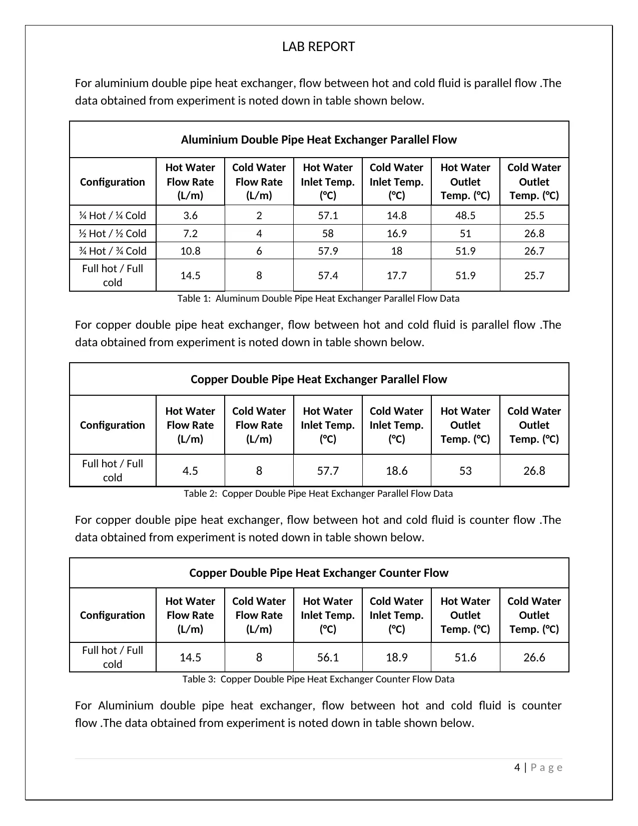
For aluminium double pipe heat exchanger, flow between hot and cold fluid is parallel flow .The
data obtained from experiment is noted down in table shown below.
Aluminium Double Pipe Heat Exchanger Parallel Flow
Configuration
Hot Water
Flow Rate
(L/m)
Cold Water
Flow Rate
(L/m)
Hot Water
Inlet Temp.
(°C)
Cold Water
Inlet Temp.
(°C)
Hot Water
Outlet
Temp. (°C)
Cold Water
Outlet
Temp. (°C)
¼ Hot / ¼ Cold 3.6 2 57.1 14.8 48.5 25.5
½ Hot / ½ Cold 7.2 4 58 16.9 51 26.8
¾ Hot / ¾ Cold 10.8 6 57.9 18 51.9 26.7
Full hot / Full
cold 14.5 8 57.4 17.7 51.9 25.7
Table 1: Aluminum Double Pipe Heat Exchanger Parallel Flow Data
For copper double pipe heat exchanger, flow between hot and cold fluid is parallel flow .The
data obtained from experiment is noted down in table shown below.
Copper Double Pipe Heat Exchanger Parallel Flow
Configuration
Hot Water
Flow Rate
(L/m)
Cold Water
Flow Rate
(L/m)
Hot Water
Inlet Temp.
(°C)
Cold Water
Inlet Temp.
(°C)
Hot Water
Outlet
Temp. (°C)
Cold Water
Outlet
Temp. (°C)
Full hot / Full
cold 4.5 8 57.7 18.6 53 26.8
Table 2: Copper Double Pipe Heat Exchanger Parallel Flow Data
For copper double pipe heat exchanger, flow between hot and cold fluid is counter flow .The
data obtained from experiment is noted down in table shown below.
Copper Double Pipe Heat Exchanger Counter Flow
Configuration
Hot Water
Flow Rate
(L/m)
Cold Water
Flow Rate
(L/m)
Hot Water
Inlet Temp.
(°C)
Cold Water
Inlet Temp.
(°C)
Hot Water
Outlet
Temp. (°C)
Cold Water
Outlet
Temp. (°C)
Full hot / Full
cold 14.5 8 56.1 18.9 51.6 26.6
Table 3: Copper Double Pipe Heat Exchanger Counter Flow Data
For Aluminium double pipe heat exchanger, flow between hot and cold fluid is counter
flow .The data obtained from experiment is noted down in table shown below.
4 | P a g e
Paraphrase This Document
Need a fresh take? Get an instant paraphrase of this document with our AI Paraphraser
LAB REPORT
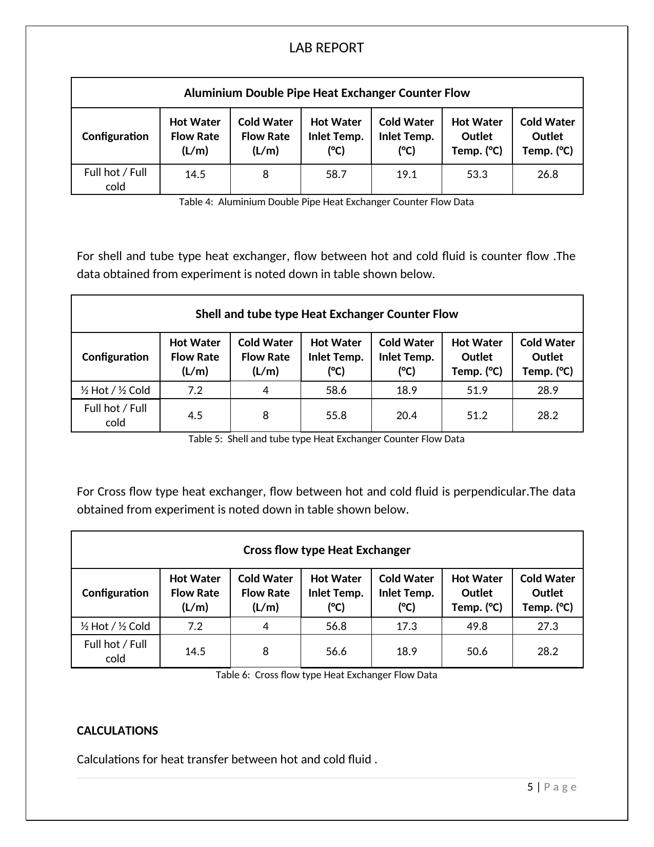
Aluminium Double Pipe Heat Exchanger Counter Flow
Configuration
Hot Water
Flow Rate
(L/m)
Cold Water
Flow Rate
(L/m)
Hot Water
Inlet Temp.
(°C)
Cold Water
Inlet Temp.
(°C)
Hot Water
Outlet
Temp. (°C)
Cold Water
Outlet
Temp. (°C)
Full hot / Full
cold
14.5 8 58.7 19.1 53.3 26.8
Table 4: Aluminium Double Pipe Heat Exchanger Counter Flow Data
For shell and tube type heat exchanger, flow between hot and cold fluid is counter flow .The
data obtained from experiment is noted down in table shown below.
Shell and tube type Heat Exchanger Counter Flow
Configuration
Hot Water
Flow Rate
(L/m)
Cold Water
Flow Rate
(L/m)
Hot Water
Inlet Temp.
(°C)
Cold Water
Inlet Temp.
(°C)
Hot Water
Outlet
Temp. (°C)
Cold Water
Outlet
Temp. (°C)
½ Hot / ½ Cold 7.2 4 58.6 18.9 51.9 28.9
Full hot / Full
cold 4.5 8 55.8 20.4 51.2 28.2
Table 5: Shell and tube type Heat Exchanger Counter Flow Data
For Cross flow type heat exchanger, flow between hot and cold fluid is perpendicular.The data
obtained from experiment is noted down in table shown below.
Cross flow type Heat Exchanger
Configuration
Hot Water
Flow Rate
(L/m)
Cold Water
Flow Rate
(L/m)
Hot Water
Inlet Temp.
(°C)
Cold Water
Inlet Temp.
(°C)
Hot Water
Outlet
Temp. (°C)
Cold Water
Outlet
Temp. (°C)
½ Hot / ½ Cold 7.2 4 56.8 17.3 49.8 27.3
Full hot / Full
cold 14.5 8 56.6 18.9 50.6 28.2
Table 6: Cross flow type Heat Exchanger Flow Data
CALCULATIONS
Calculations for heat transfer between hot and cold fluid .
5 | P a g e
LAB REPORT
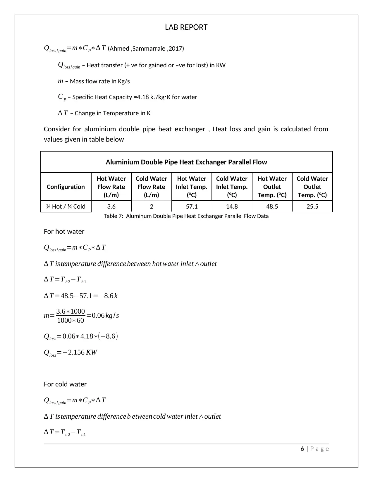
Qloss / gain=m∗CP∗∆ T (Ahmed ,Sammarraie ,2017)
Qloss / gain – Heat transfer (+ ve for gained or –ve for lost) in KW
m – Mass flow rate in Kg/s
C p – Specific Heat Capacity =4.18 kJ/kg⋅K for water
∆ T – Change in Temperature in K
Consider for aluminium double pipe heat exchanger , Heat loss and gain is calculated from
values given in table below
Aluminium Double Pipe Heat Exchanger Parallel Flow
Configuration
Hot Water
Flow Rate
(L/m)
Cold Water
Flow Rate
(L/m)
Hot Water
Inlet Temp.
(°C)
Cold Water
Inlet Temp.
(°C)
Hot Water
Outlet
Temp. (°C)
Cold Water
Outlet
Temp. (°C)
¼ Hot / ¼ Cold 3.6 2 57.1 14.8 48.5 25.5
Table 7: Aluminum Double Pipe Heat Exchanger Parallel Flow Data
For hot water
Qloss / gain=m∗CP∗∆ T
∆ T istemperature difference between hot water inlet ∧outlet
∆ T =T h 2−T h 1
∆ T =48.5−57.1=−8.6 k
m= 3.6∗1000
1000∗60 =0.06 kg /s
Qloss=0.06∗4.18∗(−8.6)
Qloss=−2.156 KW
For cold water
Qloss / gain=m∗CP∗∆ T
∆ T istemperature difference b etween cold water inlet∧outlet
∆ T =T c 2−T c1
6 | P a g e
⊘ This is a preview!⊘
Do you want full access?
Subscribe today to unlock all pages.
Trusted by 1+ million students worldwide
LAB REPORT
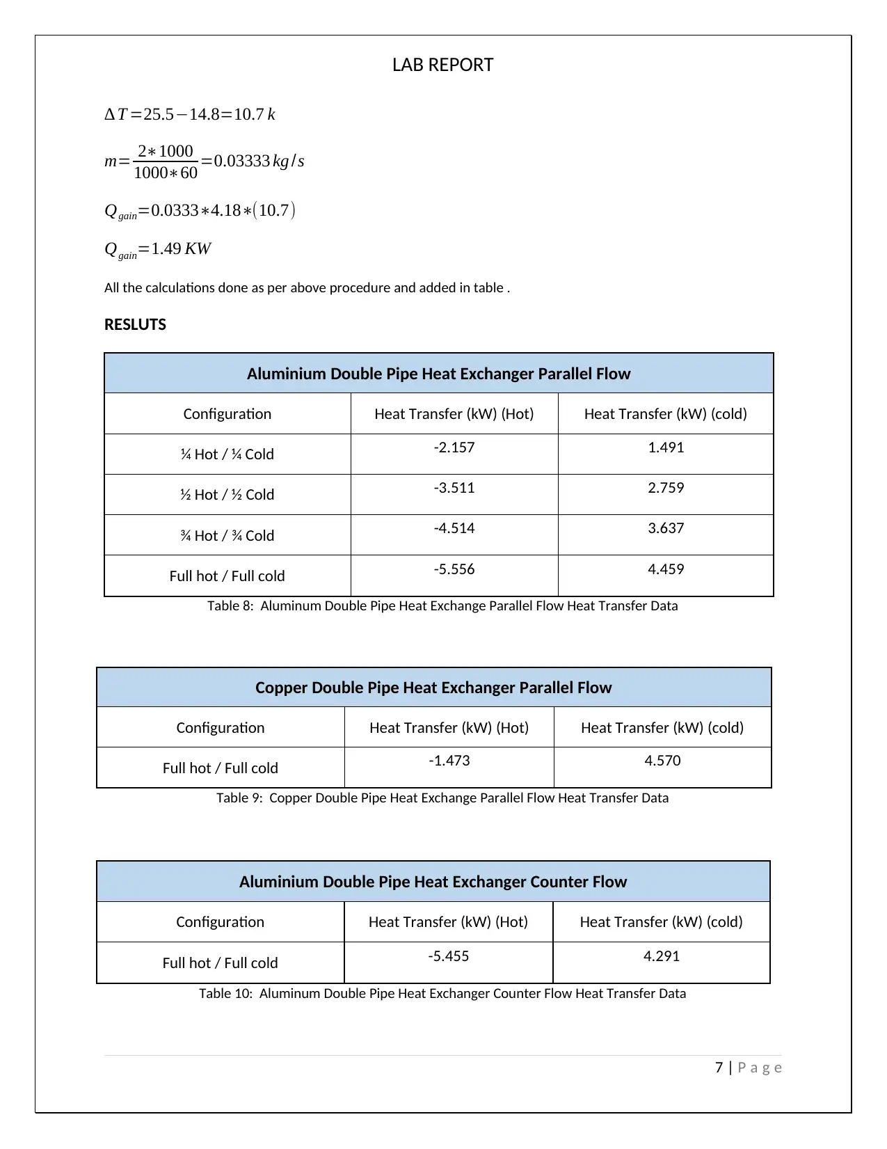
∆ T =25.5−14.8=10.7 k
m= 2∗1000
1000∗60 =0.03333 kg /s
Qgain=0.0333∗4.18∗(10.7)
Qgain=1.49 KW
All the calculations done as per above procedure and added in table .
RESLUTS
Aluminium Double Pipe Heat Exchanger Parallel Flow
Configuration Heat Transfer (kW) (Hot) Heat Transfer (kW) (cold)
¼ Hot / ¼ Cold -2.157 1.491
½ Hot / ½ Cold -3.511 2.759
¾ Hot / ¾ Cold -4.514 3.637
Full hot / Full cold -5.556 4.459
Table 8: Aluminum Double Pipe Heat Exchange Parallel Flow Heat Transfer Data
Copper Double Pipe Heat Exchanger Parallel Flow
Configuration Heat Transfer (kW) (Hot) Heat Transfer (kW) (cold)
Full hot / Full cold -1.473 4.570
Table 9: Copper Double Pipe Heat Exchange Parallel Flow Heat Transfer Data
Aluminium Double Pipe Heat Exchanger Counter Flow
Configuration Heat Transfer (kW) (Hot) Heat Transfer (kW) (cold)
Full hot / Full cold -5.455 4.291
Table 10: Aluminum Double Pipe Heat Exchanger Counter Flow Heat Transfer Data
7 | P a g e
Paraphrase This Document
Need a fresh take? Get an instant paraphrase of this document with our AI Paraphraser
LAB REPORT
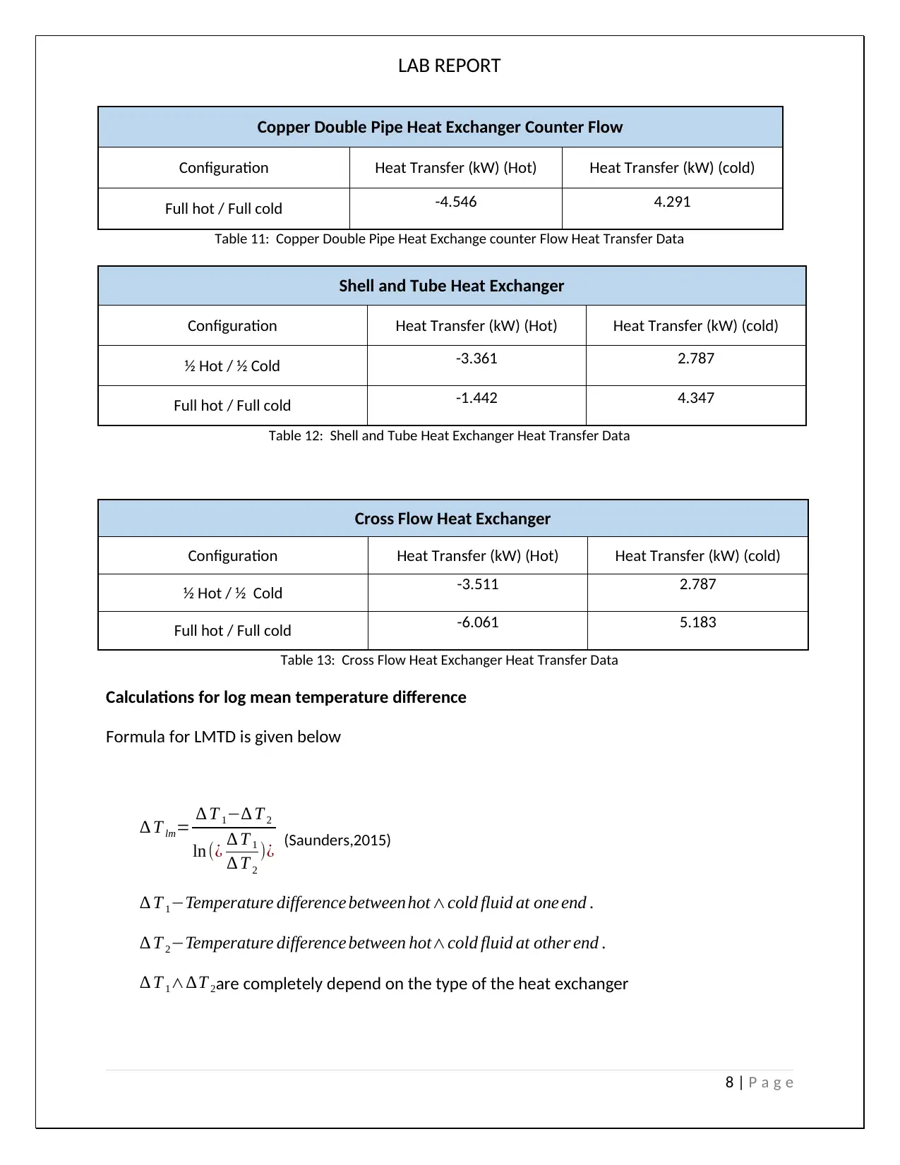
Copper Double Pipe Heat Exchanger Counter Flow
Configuration Heat Transfer (kW) (Hot) Heat Transfer (kW) (cold)
Full hot / Full cold -4.546 4.291
Table 11: Copper Double Pipe Heat Exchange counter Flow Heat Transfer Data
Shell and Tube Heat Exchanger
Configuration Heat Transfer (kW) (Hot) Heat Transfer (kW) (cold)
½ Hot / ½ Cold -3.361 2.787
Full hot / Full cold -1.442 4.347
Table 12: Shell and Tube Heat Exchanger Heat Transfer Data
Cross Flow Heat Exchanger
Configuration Heat Transfer (kW) (Hot) Heat Transfer (kW) (cold)
½ Hot / ½ Cold -3.511 2.787
Full hot / Full cold -6.061 5.183
Table 13: Cross Flow Heat Exchanger Heat Transfer Data
Calculations for log mean temperature difference
Formula for LMTD is given below
∆ T lm= ∆ T 1−∆ T 2
ln (¿ ∆ T 1
∆ T 2
)¿ (Saunders,2015)
∆ T 1−Temperature difference between hot∧cold fluid at one end .
∆ T 2−Temperature difference between hot∧cold fluid at other end .
∆ T 1∧∆T 2are completely depend on the type of the heat exchanger
8 | P a g e
LAB REPORT
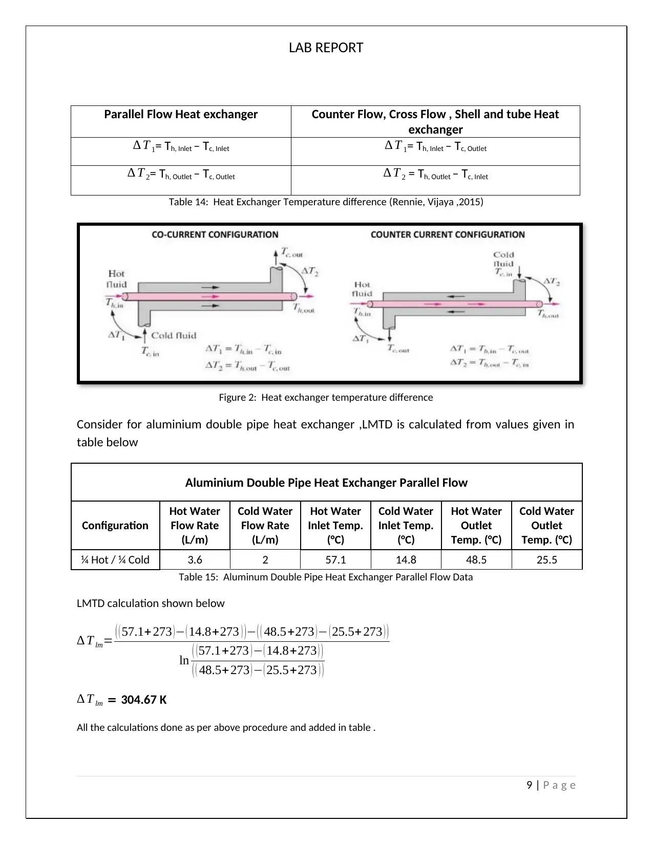
Parallel Flow Heat exchanger Counter Flow, Cross Flow , Shell and tube Heat
exchanger
∆ T 1= Th, Inlet – Tc, Inlet ∆ T 1= Th, Inlet – Tc, Outlet
∆ T 2= Th, Outlet – Tc, Outlet ∆ T 2 = Th, Outlet – Tc, Inlet
Table 14: Heat Exchanger Temperature difference (Rennie, Vijaya ,2015)
Figure 2: Heat exchanger temperature difference
Consider for aluminium double pipe heat exchanger ,LMTD is calculated from values given in
table below
Aluminium Double Pipe Heat Exchanger Parallel Flow
Configuration
Hot Water
Flow Rate
(L/m)
Cold Water
Flow Rate
(L/m)
Hot Water
Inlet Temp.
(°C)
Cold Water
Inlet Temp.
(°C)
Hot Water
Outlet
Temp. (°C)
Cold Water
Outlet
Temp. (°C)
¼ Hot / ¼ Cold 3.6 2 57.1 14.8 48.5 25.5
Table 15: Aluminum Double Pipe Heat Exchanger Parallel Flow Data
LMTD calculation shown below
∆ T lm= ( ( 57.1+ 273 )− ( 14.8+273 ) )− ( ( 48.5+273 )− ( 25.5+ 273 ) )
ln ( (57.1+273 )− ( 14.8+273 ) )
( ( 48.5+273 )− ( 25.5+273 ) )
∆ T lm = 304.67 K
All the calculations done as per above procedure and added in table .
9 | P a g e
⊘ This is a preview!⊘
Do you want full access?
Subscribe today to unlock all pages.
Trusted by 1+ million students worldwide
LAB REPORT
Aluminium Double Pipe Heat Exchanger Parallel Flow LMTD(K)
¼ Hot / ¼ Cold 304.68
½ Hot / ½ Cold 304.91
¾ Hot / ¾ Cold 304.99
Full hot / Full cold 305.48
Aluminium Double Pipe Heat Exchanger Counter Flow LMTD(K)
Full hot / Full cold 306.04
Copper Double Pipe Heat Exchanger Parallel Flow LMTD(K)
Full hot / Full cold 305.22
Copper Double Pipe Heat Exchanger Counter Flow LMTD(K)
Full hot / Full cold 304.07
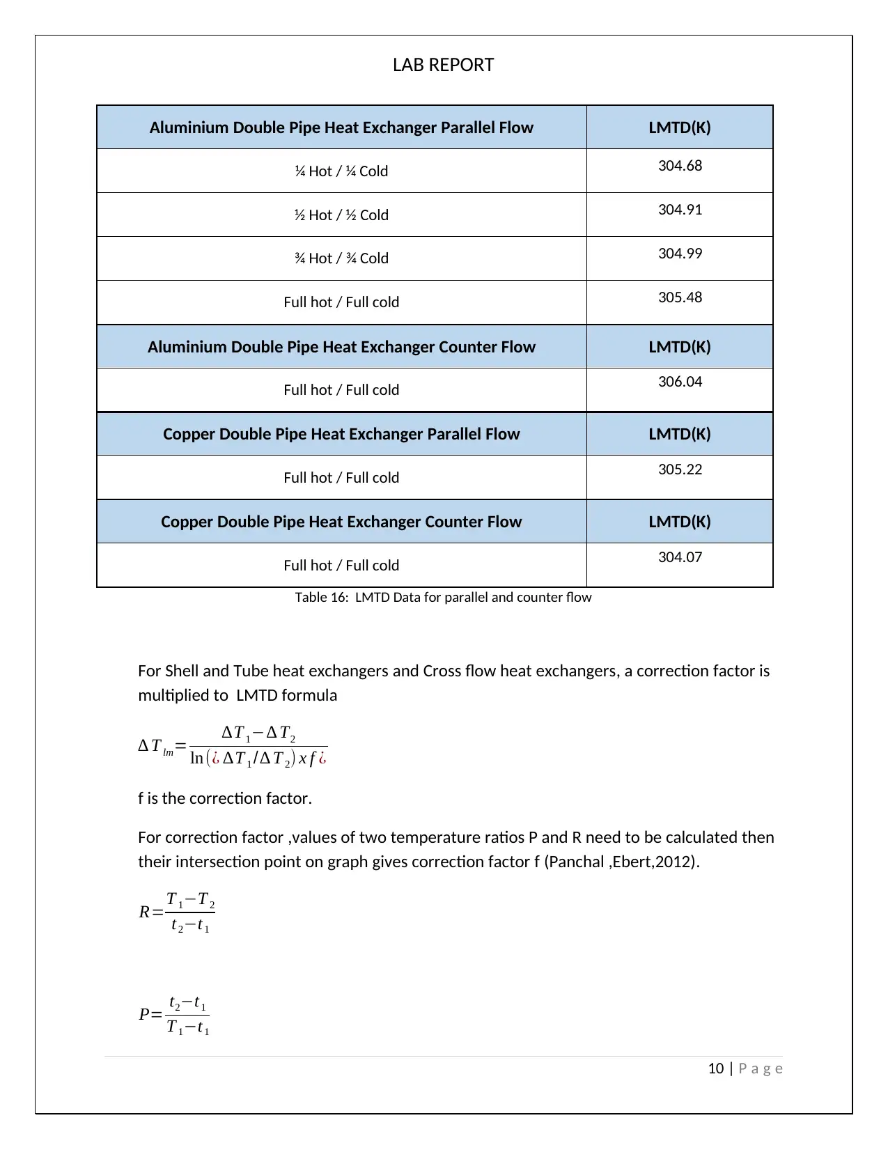
Table 16: LMTD Data for parallel and counter flow
For Shell and Tube heat exchangers and Cross flow heat exchangers, a correction factor is
multiplied to LMTD formula
∆ T lm= ∆T 1−∆ T2
ln(¿ ∆T 1 /∆ T 2) x f ¿
f is the correction factor.
For correction factor ,values of two temperature ratios P and R need to be calculated then
their intersection point on graph gives correction factor f (Panchal ,Ebert,2012).
R=T 1−T 2
t2−t1
P= t2−t1
T 1−t1
10 | P a g e
Aluminium Double Pipe Heat Exchanger Parallel Flow LMTD(K)
¼ Hot / ¼ Cold 304.68
½ Hot / ½ Cold 304.91
¾ Hot / ¾ Cold 304.99
Full hot / Full cold 305.48
Aluminium Double Pipe Heat Exchanger Counter Flow LMTD(K)
Full hot / Full cold 306.04
Copper Double Pipe Heat Exchanger Parallel Flow LMTD(K)
Full hot / Full cold 305.22
Copper Double Pipe Heat Exchanger Counter Flow LMTD(K)
Full hot / Full cold 304.07
Table 16: LMTD Data for parallel and counter flow
For Shell and Tube heat exchangers and Cross flow heat exchangers, a correction factor is
multiplied to LMTD formula
∆ T lm= ∆T 1−∆ T2
ln(¿ ∆T 1 /∆ T 2) x f ¿
f is the correction factor.
For correction factor ,values of two temperature ratios P and R need to be calculated then
their intersection point on graph gives correction factor f (Panchal ,Ebert,2012).
R=T 1−T 2
t2−t1
P= t2−t1
T 1−t1
10 | P a g e
Paraphrase This Document
Need a fresh take? Get an instant paraphrase of this document with our AI Paraphraser
LAB REPORT
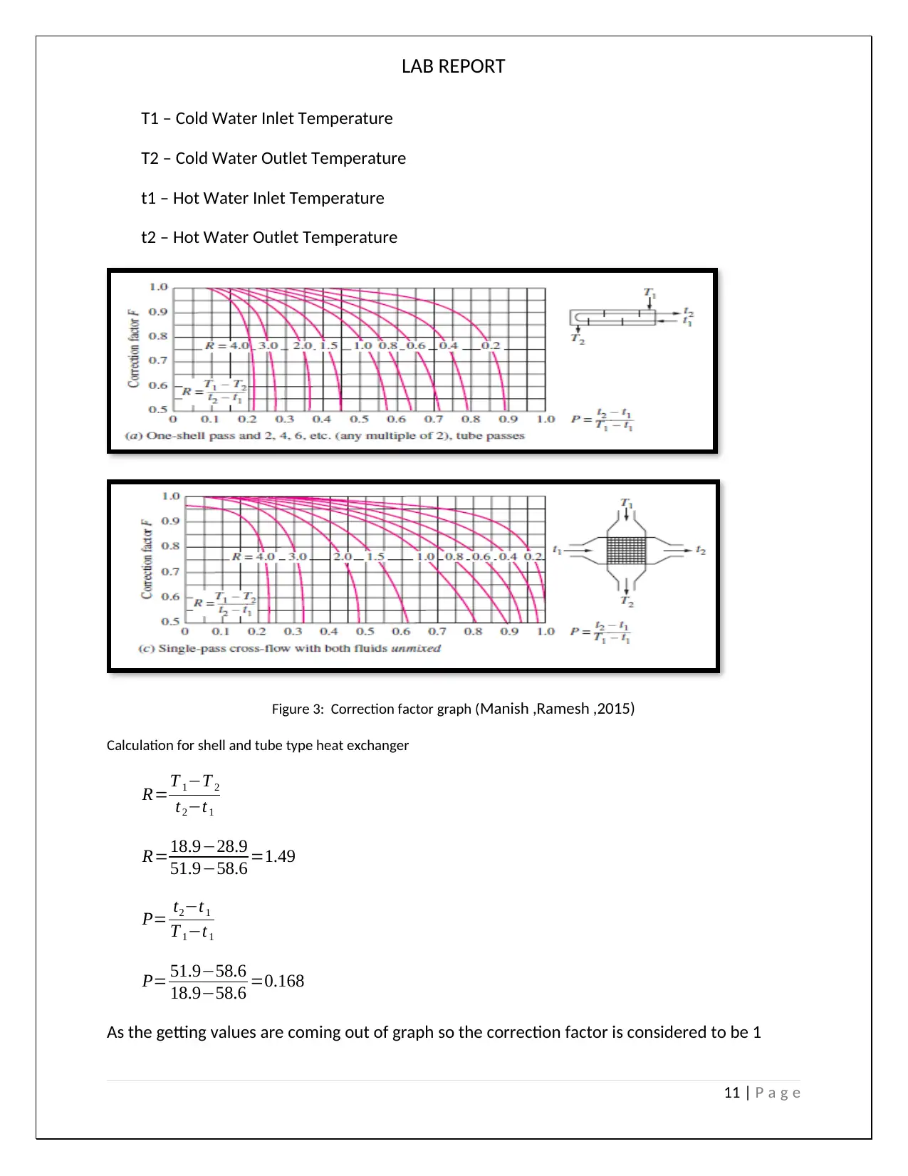
T1 – Cold Water Inlet Temperature
T2 – Cold Water Outlet Temperature
t1 – Hot Water Inlet Temperature
t2 – Hot Water Outlet Temperature
Figure 3: Correction factor graph (Manish ,Ramesh ,2015)
Calculation for shell and tube type heat exchanger
R=T 1−T 2
t2−t1
R=18.9−28.9
51.9−58.6 =1.49
P= t2−t1
T 1−t1
P= 51.9−58.6
18.9−58.6 =0.168
As the getting values are coming out of graph so the correction factor is considered to be 1
11 | P a g e
LAB REPORT
∆ T lm= ∆T 1−∆ T2
ln(¿ ∆T 1 /∆ T 2) x f ¿
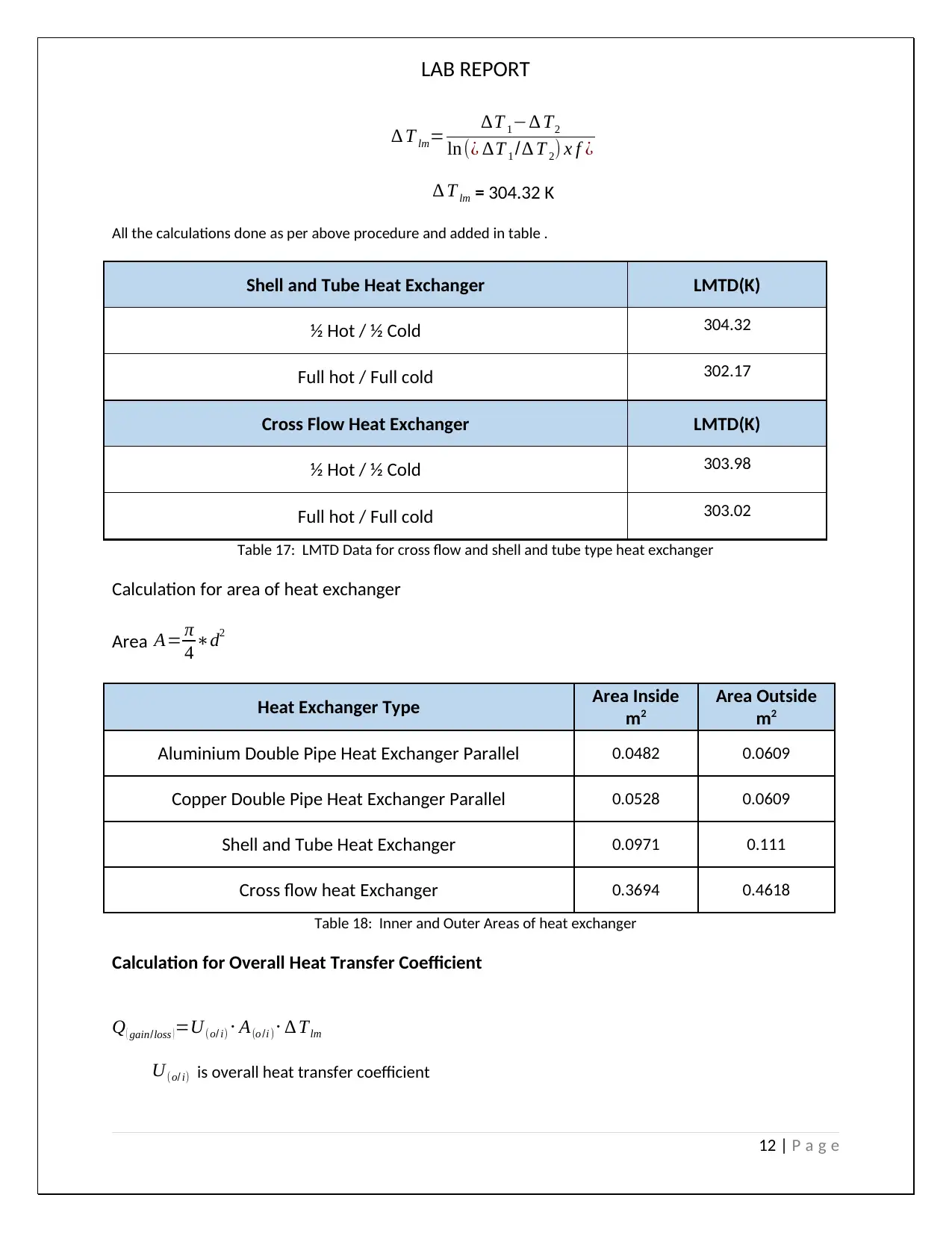
∆ T lm = 304.32 K
All the calculations done as per above procedure and added in table .
Shell and Tube Heat Exchanger LMTD(K)
½ Hot / ½ Cold 304.32
Full hot / Full cold 302.17
Cross Flow Heat Exchanger LMTD(K)
½ Hot / ½ Cold 303.98
Full hot / Full cold 303.02
Table 17: LMTD Data for cross flow and shell and tube type heat exchanger
Calculation for area of heat exchanger
Area A= π
4 ∗d2
Heat Exchanger Type Area Inside
m2
Area Outside
m2
Aluminium Double Pipe Heat Exchanger Parallel 0.0482 0.0609
Copper Double Pipe Heat Exchanger Parallel 0.0528 0.0609
Shell and Tube Heat Exchanger 0.0971 0.111
Cross flow heat Exchanger 0.3694 0.4618
Table 18: Inner and Outer Areas of heat exchanger
Calculation for Overall Heat Transfer Coefficient
Q ( gain/loss ) =U(o/ i) ⋅ A(o /i )⋅ ∆ Tlm
U(o/ i) is overall heat transfer coefficient
12 | P a g e
∆ T lm= ∆T 1−∆ T2
ln(¿ ∆T 1 /∆ T 2) x f ¿
∆ T lm = 304.32 K
All the calculations done as per above procedure and added in table .
Shell and Tube Heat Exchanger LMTD(K)
½ Hot / ½ Cold 304.32
Full hot / Full cold 302.17
Cross Flow Heat Exchanger LMTD(K)
½ Hot / ½ Cold 303.98
Full hot / Full cold 303.02
Table 17: LMTD Data for cross flow and shell and tube type heat exchanger
Calculation for area of heat exchanger
Area A= π
4 ∗d2
Heat Exchanger Type Area Inside
m2
Area Outside
m2
Aluminium Double Pipe Heat Exchanger Parallel 0.0482 0.0609
Copper Double Pipe Heat Exchanger Parallel 0.0528 0.0609
Shell and Tube Heat Exchanger 0.0971 0.111
Cross flow heat Exchanger 0.3694 0.4618
Table 18: Inner and Outer Areas of heat exchanger
Calculation for Overall Heat Transfer Coefficient
Q ( gain/loss ) =U(o/ i) ⋅ A(o /i )⋅ ∆ Tlm
U(o/ i) is overall heat transfer coefficient
12 | P a g e
⊘ This is a preview!⊘
Do you want full access?
Subscribe today to unlock all pages.
Trusted by 1+ million students worldwide
1 out of 17
Related Documents


Your All-in-One AI-Powered Toolkit for Academic Success.
+13062052269
info@desklib.com
Available 24*7 on WhatsApp / Email
![[object Object]](/_next/static/media/star-bottom.7253800d.svg)
Unlock your academic potential
Copyright © 2020–2026 A2Z Services. All Rights Reserved. Developed and managed by ZUCOL.