MHM-HT1: Heat Transfer in a Heat Exchanger Experiment Report
VerifiedAdded on 2022/08/31
|12
|2575
|48
Report
AI Summary
This report details an experiment on heat exchangers, focusing on the effects of geometry and operating conditions on the cooling rate of a fluid, specifically water. The experiment compared plate, shell and tube, and double-pipe heat exchangers, examining the influence of fluid flow rate, stirring speed, and water mass on cooling time and equilibrium temperature. The results indicated that lower stirring speeds and larger temperature differences between inlet and outlet streams led to faster cooling. The report includes calculations of heat transfer coefficients and a discussion of pressure drop considerations in heat exchanger design. It also involves deriving and validating an unsteady-state energy balance to model the temperature change in the tank, and a discussion of the various heat exchanger types, their applications, and the factors influencing their performance. The study aimed to critically assess the operating conditions required to achieve the desired temperature and to compare the heat transfer behaviors across different heat exchanger geometries.
Heat Exchanger 1
Heat Transfer in a Heat Exchanger
Student’s Name
Institutional Affiliation
Date
Heat Transfer in a Heat Exchanger
Student’s Name
Institutional Affiliation
Date
Paraphrase This Document
Need a fresh take? Get an instant paraphrase of this document with our AI Paraphraser
Heat Exchanger 2
Abstract
The purpose of this laboratory exercise was to examine the effect of geometry and operating
conditions on the cooling rate of a fluid inside a heat exchanger. The fluid used was water at 50 ℃
with expected cooling to about 30 ℃ for the plate exchanger and 43 ℃ for both the shell and tube
and double-pipe exchangers. The operating conditions under investigation were the fluid flowrate,
stirring speed and the mass of the water. The results showed that lower stirring speed resulted in lower
equilibrium time. The lowest equilibrium time of 8 minutes was obtained at a stirring speed of 2.5 and
a hot water flow rate of 2 l/min. as expected the lower cooling time was obtained for larger
differences in temperature between the inlet and outlet fluid streams.
Aim
The aim of the experiment was to compare and contrast the impact of operating conditions and
geometry on the cooling of a fluid inside a heat exchanger.
Objectives
i) To calculate heat transfer coefficients based on the experimental data obtained.
ii) To investigate the effect of different heat exchanger geometries the heat transfer
iii) To critically examine the operating condition combinations that could give the desired
temperature.
iv) To examine the phase space of process conditions available with the experimental rig
such that it is possible to cool the hot water at 50 ℃ to the required temperature for a
particular heat exchanger module.
Introduction
A heat exchanger is a device used to transfer heat between fluids at different temperatures. The heat
exchange can occur between a utility stream (pressurized steam or cold water) and a process stream,
between two process streams which result in energy integration or a power source and a process
stream (Rathore & Kapuno, 2011). Usually, the term heat exchanger is used to refer to all the
equipment that transfer heat between two fluids. Several types of heat exchangers are used in the
process industry. These include shell and tube exchangers, plate-fin exchangers, hairpin exchangers,
and spiral heat exchangers. The choice of the particular type of exchanger for a particular application
depends on several factors such as temperature range, pressure drop, corrosion, capital, and operating
costs.
Pressure drop in heat exchangers
In the design of heat exchangers, pressure drop is an important consideration. A number of factors
affect pressure drop. These include the passage geometry and the type flow, laminar or turbulent
(Martin, 2010). Pressure drop calculations are necessary for both streams. The flow normally consists
of either an internal and external stream or two internal streams. Initially, the fluid undergoes entrance
loss as it enters the heat exchange as a result of a sudden reduction in the flow area. Internal losses
and loss due to friction in the core are other contributions ("Pressure Drop Across Plate Heat
Exchangers," 2017). Finally, as the fluid exits from the exchanger, it undergoes a sudden expansion
Heat Exchanger 3
The entrance loss results from abrupt contraction and can be obtained from Bernoulli’s equation
considering mass conservation and a loss coefficient giving,
∆ pi =0.5 G2
ρi
(1−σ i
2+ K c)
Where G= ˙m
A is the mass flux of the fluid and σ is the contraction ratio of the passage. Generally,
σ = minimum flow area
frontal area
Core loss
Inside the core, the pressure drop may be written in terms of fanning friction factor,
∆ pc= 4 fL G2
2 Dh ρm
To obtain a momentum balance equation across the core, we consider acceleration or deceleration in
the fluid due to changes in density,
∆ pa Ac= ˙m(V e−V i)
This equation may be rewritten as follows,
∆ pa=G2
( 1
ρe
− 1
ρi )
Since Gi=Ge we write V = G
ρ
Exit loss
The sudden expansion of the flow at the exit can be modeled using Bernoulli’s equation combined
with mass conservation as follows,
∆ pi =−0.5 G2
ρi
(1−σi
2−Kc )
Total pressure drop
The total pressure drop across the heat exchanger is given by the sum of all the above contributions,
∆ p=∆ pi +∆ pc +∆ pa+∆ pe
∆ p= G2
2 ρi [ ( 1−σi
2−Kc )+ 4 fL
Dh ( ρi
ρm )+2 ( ρi
ρe
−1 )−(1−σ i
2−Kc) ( ρi
ρe ) ]
The above equation gives the total pressure drop across the heat exchanger.
⊘ This is a preview!⊘
Do you want full access?
Subscribe today to unlock all pages.
Trusted by 1+ million students worldwide
Heat Exchanger 4
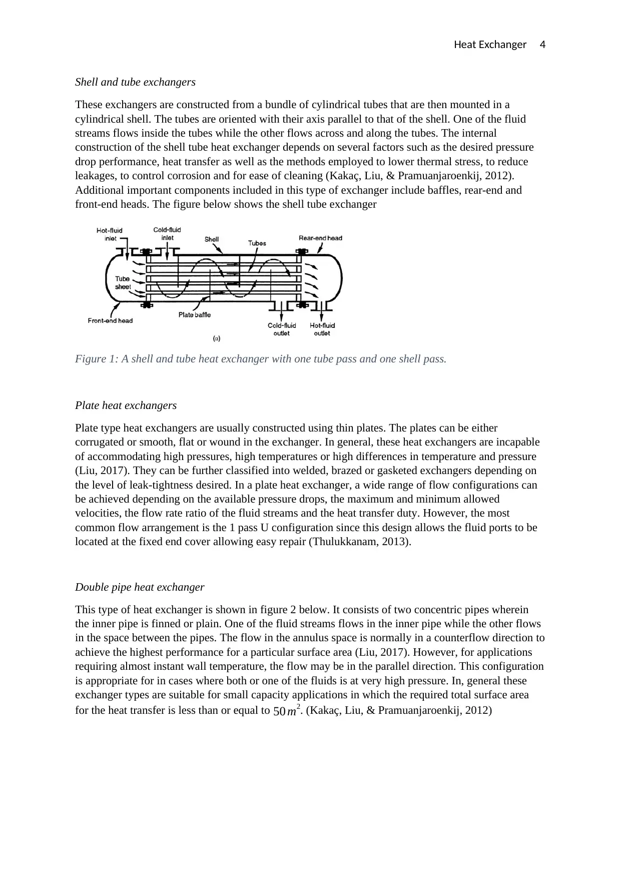
Shell and tube exchangers
These exchangers are constructed from a bundle of cylindrical tubes that are then mounted in a
cylindrical shell. The tubes are oriented with their axis parallel to that of the shell. One of the fluid
streams flows inside the tubes while the other flows across and along the tubes. The internal
construction of the shell tube heat exchanger depends on several factors such as the desired pressure
drop performance, heat transfer as well as the methods employed to lower thermal stress, to reduce
leakages, to control corrosion and for ease of cleaning (Kakaç, Liu, & Pramuanjaroenkij, 2012).
Additional important components included in this type of exchanger include baffles, rear-end and
front-end heads. The figure below shows the shell tube exchanger
Figure 1: A shell and tube heat exchanger with one tube pass and one shell pass.
Plate heat exchangers
Plate type heat exchangers are usually constructed using thin plates. The plates can be either
corrugated or smooth, flat or wound in the exchanger. In general, these heat exchangers are incapable
of accommodating high pressures, high temperatures or high differences in temperature and pressure
(Liu, 2017). They can be further classified into welded, brazed or gasketed exchangers depending on
the level of leak-tightness desired. In a plate heat exchanger, a wide range of flow configurations can
be achieved depending on the available pressure drops, the maximum and minimum allowed
velocities, the flow rate ratio of the fluid streams and the heat transfer duty. However, the most
common flow arrangement is the 1 pass U configuration since this design allows the fluid ports to be
located at the fixed end cover allowing easy repair (Thulukkanam, 2013).
Double pipe heat exchanger
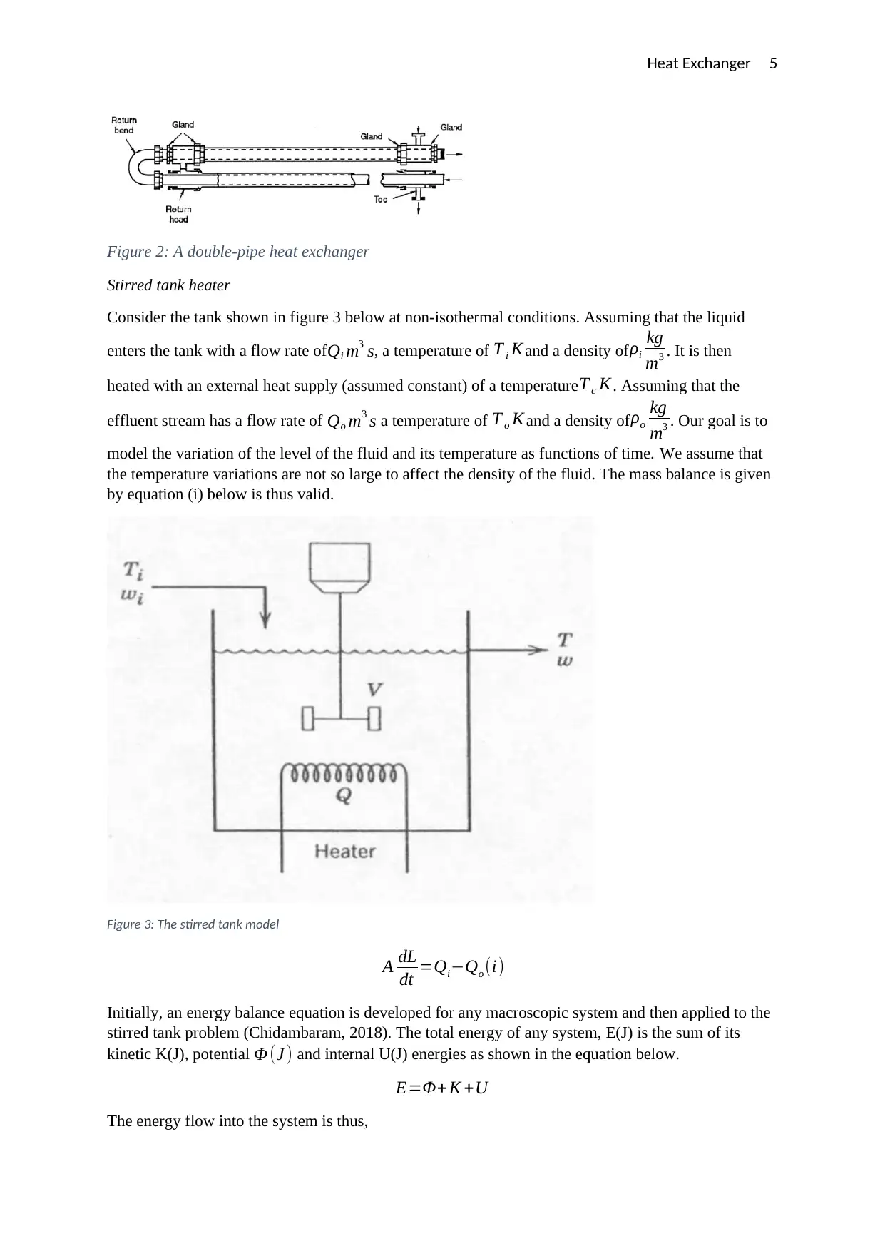
This type of heat exchanger is shown in figure 2 below. It consists of two concentric pipes wherein
the inner pipe is finned or plain. One of the fluid streams flows in the inner pipe while the other flows
in the space between the pipes. The flow in the annulus space is normally in a counterflow direction to
achieve the highest performance for a particular surface area (Liu, 2017). However, for applications
requiring almost instant wall temperature, the flow may be in the parallel direction. This configuration
is appropriate for in cases where both or one of the fluids is at very high pressure. In, general these
exchanger types are suitable for small capacity applications in which the required total surface area
for the heat transfer is less than or equal to 50 m2. (Kakaç, Liu, & Pramuanjaroenkij, 2012)
Shell and tube exchangers
These exchangers are constructed from a bundle of cylindrical tubes that are then mounted in a
cylindrical shell. The tubes are oriented with their axis parallel to that of the shell. One of the fluid
streams flows inside the tubes while the other flows across and along the tubes. The internal
construction of the shell tube heat exchanger depends on several factors such as the desired pressure
drop performance, heat transfer as well as the methods employed to lower thermal stress, to reduce
leakages, to control corrosion and for ease of cleaning (Kakaç, Liu, & Pramuanjaroenkij, 2012).
Additional important components included in this type of exchanger include baffles, rear-end and
front-end heads. The figure below shows the shell tube exchanger
Figure 1: A shell and tube heat exchanger with one tube pass and one shell pass.
Plate heat exchangers
Plate type heat exchangers are usually constructed using thin plates. The plates can be either
corrugated or smooth, flat or wound in the exchanger. In general, these heat exchangers are incapable
of accommodating high pressures, high temperatures or high differences in temperature and pressure
(Liu, 2017). They can be further classified into welded, brazed or gasketed exchangers depending on
the level of leak-tightness desired. In a plate heat exchanger, a wide range of flow configurations can
be achieved depending on the available pressure drops, the maximum and minimum allowed
velocities, the flow rate ratio of the fluid streams and the heat transfer duty. However, the most
common flow arrangement is the 1 pass U configuration since this design allows the fluid ports to be
located at the fixed end cover allowing easy repair (Thulukkanam, 2013).
Double pipe heat exchanger
This type of heat exchanger is shown in figure 2 below. It consists of two concentric pipes wherein
the inner pipe is finned or plain. One of the fluid streams flows in the inner pipe while the other flows
in the space between the pipes. The flow in the annulus space is normally in a counterflow direction to
achieve the highest performance for a particular surface area (Liu, 2017). However, for applications
requiring almost instant wall temperature, the flow may be in the parallel direction. This configuration
is appropriate for in cases where both or one of the fluids is at very high pressure. In, general these
exchanger types are suitable for small capacity applications in which the required total surface area
for the heat transfer is less than or equal to 50 m2. (Kakaç, Liu, & Pramuanjaroenkij, 2012)
Paraphrase This Document
Need a fresh take? Get an instant paraphrase of this document with our AI Paraphraser
Heat Exchanger 5
Figure 2: A double-pipe heat exchanger
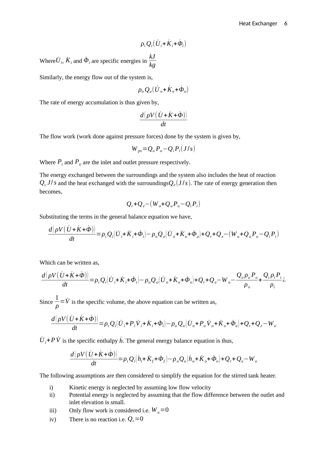
Stirred tank heater
Consider the tank shown in figure 3 below at non-isothermal conditions. Assuming that the liquid
enters the tank with a flow rate of Qi m3 s, a temperature of T i K and a density of ρi
kg
m3 . It is then
heated with an external heat supply (assumed constant) of a temperature T c K. Assuming that the
effluent stream has a flow rate of Qo m3 s a temperature of T o K and a density ofρo
kg
m3 . Our goal is to
model the variation of the level of the fluid and its temperature as functions of time. We assume that
the temperature variations are not so large to affect the density of the fluid. The mass balance is given
by equation (i) below is thus valid.
Figure 3: The stirred tank model
A dL
dt =Qi−Qo (i)
Initially, an energy balance equation is developed for any macroscopic system and then applied to the
stirred tank problem (Chidambaram, 2018). The total energy of any system, E(J) is the sum of its
kinetic K(J), potential Φ (J ) and internal U(J) energies as shown in the equation below.
E=Φ+ K +U
The energy flow into the system is thus,
Figure 2: A double-pipe heat exchanger
Stirred tank heater
Consider the tank shown in figure 3 below at non-isothermal conditions. Assuming that the liquid
enters the tank with a flow rate of Qi m3 s, a temperature of T i K and a density of ρi
kg
m3 . It is then
heated with an external heat supply (assumed constant) of a temperature T c K. Assuming that the
effluent stream has a flow rate of Qo m3 s a temperature of T o K and a density ofρo
kg
m3 . Our goal is to
model the variation of the level of the fluid and its temperature as functions of time. We assume that
the temperature variations are not so large to affect the density of the fluid. The mass balance is given
by equation (i) below is thus valid.
Figure 3: The stirred tank model
A dL
dt =Qi−Qo (i)
Initially, an energy balance equation is developed for any macroscopic system and then applied to the
stirred tank problem (Chidambaram, 2018). The total energy of any system, E(J) is the sum of its
kinetic K(J), potential Φ (J ) and internal U(J) energies as shown in the equation below.
E=Φ+ K +U
The energy flow into the system is thus,
Heat Exchanger 6
ρi Qi ( ˙Ui + ˙Ki + ˙Φi )
Where ˙Ui, ˙Ki and ˙Φi are specific energies in kJ
kg
Similarly, the energy flow out of the system is,
ρo Qo ( ˙U o + ˙Ko + ˙Φo)
The rate of energy accumulation is thus given by,
d ( ρV ( ˙U + ˙K + ˙Φ) )
dt
The flow work (work done against pressure forces) done by the system is given by,
W pv =Qo Po −Qi Pi (J /s)
Where Pi and Po are the inlet and outlet pressure respectively.
The energy exchanged between the surroundings and the system also includes the heat of reaction
Qr J / s and the heat exchanged with the surroundingsQe (J /s ). The rate of energy generation then
becomes,
Qr +Qe−(W o+Qo Po −Qi Pi )
Substituting the terms in the general balance equation we have,
d ( ρV ( ˙U + ˙K + ˙Φ) )
dt =ρi Qi ( ˙U i+ ˙K i+ ˙Φi )− ρo Qo ( ˙U o + ˙Ko + ˙Φo ) +Qr +Qe−(W o +Qo Po −Qi Pi )
Which can be written as,
d ( ρV ( ˙U + ˙K + ˙Φ) )
dt =ρi Qi ( ˙U i+ ˙K i+ ˙Φi )− ρo Qo ( ˙U o + ˙Ko + ˙Φo ) +Qr +Qe−W o− Qo ρo Po
ρo
+ Qi ρi Pi
ρi
¿
Since 1
ρ = ˙V is the specific volume, the above equation can be written as,
d ( ρV ( ˙U + ˙K + ˙Φ) )
dt =ρi Qi ( ˙U i+ Pi ˙V i + ˙Ki + ˙Φi ) −ρo Qo ( ˙Uo +Po ˙V o + ˙K o+ ˙Φo ) +Qr +Qe−Wo
˙Ui +P ˙V is the specific enthalpy ˙h. The general energy balance equation is thus,
d ( ρV ( ˙U + ˙K + ˙Φ) )
dt =ρi Qi ( ˙hi+ ˙Kf + ˙Φf )−ρo Qo ( ˙ho + ˙K o+ ˙Φo ) +Qr + Qe−W o
The following assumptions are then considered to simplify the equation for the stirred tank heater.
i) Kinetic energy is neglected by assuming low flow velocity
ii) Potential energy is neglected by assuming that the flow difference between the outlet and
inlet elevation is small.
iii) Only flow work is considered i.e. W o =0
iv) There is no reaction i.e. Qr =0
⊘ This is a preview!⊘
Do you want full access?
Subscribe today to unlock all pages.
Trusted by 1+ million students worldwide
Heat Exchanger 7
The energy balance equation reduces to,
d ( ρV ˙U )
dt =ρi Qi ˙hi−ρo Qo ˙ho +Qe
It is possible to approximate the internal energy ˙U by the enthalpy ˙h which is, in turn, a function of
temperature and pressure.
˙h= ˙C p(T −T ref )
˙C p is the average heat capacity. Furthermore, the process temperature and the effluent temperature
T o are equal. Assuming constant density ρi= ρo=ρ the energy balance can be written as,
˙ρC p d ( V (T −Tref ) )
dt =ρ Qi ˙C p ( T i−T ref ) − ρQ0 ˙C p ( T −T ref ) + Qe
Assuming T ref =0
˙ρC p d ( VT )
dt = ρQi ˙C p Ti− ρQ0 ˙C pT +Qe
d ( VT )
dt =Qi T i−Q0 T + Qe
˙ρC p
Now, since
d ( VT )
dt =V dT
dt +T dV
dt
V dT
dt +T ( Qi−Q0 ) =Qi Ti −Q0 T + Qe
˙ρC p
V dT
dt =Qi Ti −Q0 T −T Qi+T Q0 + Qe
˙ρC p
V dT
dt =Qi Ti −T Qi + Qe
˙ρC p
V dT
dt =Qi (T i−T )+ Qe
˙ρC p
Apparatus
Three modular heat exchangers mounted onto WL110 experimental rig with the following modules
were provided.
i) Tubular double-pipe heat exchanger
ii) Plate heat exchanger
iii) Shell and tube heat exchanger
Controls on the modules are provided to vary the flowrates of the cold and hot fluids and to change
the configuration of the flow (c- or counter-current).
Paraphrase This Document
Need a fresh take? Get an instant paraphrase of this document with our AI Paraphraser
Heat Exchanger 8
Procedure
i) Safety was ensured by wearing safety goggles and a lab coat
ii) The operations of all the control on the test rig were noted
iii) The temperature of the hot fluid reservoir was set at 50 ℃ and hot fluid pump activated
iv) The delivery tubes for the cold fluid were then connected to the appropriate points on the
heat exchanger.
v) The control valves were adjusted to set the fluid flowrates at the appropriate values
vi) The values of all the necessary variables were then recorded using the hardware.
Additionally, a particular set of conditions were investigated using a batch vessel for a period of 20
minutes and the data uploaded to an online source as directed. The following output variables were
monitored.
i) The temperatures of the inflow and return streams for the hot fluid
ii) The temperatures of the inflow and return streams for the cold fluid
iii) The temperature of intermediate points
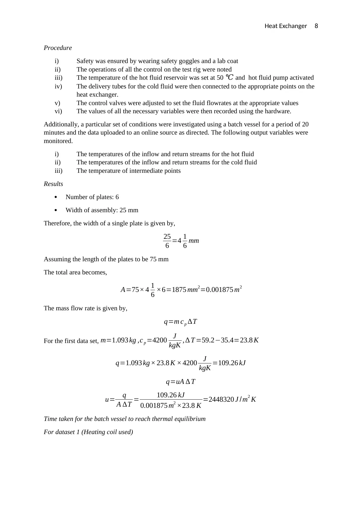
Results
Number of plates: 6
Width of assembly: 25 mm
Therefore, the width of a single plate is given by,
25
6 =4 1
6 mm
Assuming the length of the plates to be 75 mm
The total area becomes,
A=75× 4 1
6 ×6=1875 mm2=0.001875 m2
The mass flow rate is given by,
q=m c p ∆T
For the first data set, m=1.093 kg ,c p =4200 J
kgK , ∆ T =59.2−35.4=23.8 K
q=1.093 kg × 23.8 K × 4200 J
kgK =109.26 kJ
q=uA ∆ T
u= q
A ∆T = 109.26 kJ
0.001875 m2 ×23.8 K =2448320 J /m2 K
Time taken for the batch vessel to reach thermal equilibrium
For dataset 1 (Heating coil used)
Procedure
i) Safety was ensured by wearing safety goggles and a lab coat
ii) The operations of all the control on the test rig were noted
iii) The temperature of the hot fluid reservoir was set at 50 ℃ and hot fluid pump activated
iv) The delivery tubes for the cold fluid were then connected to the appropriate points on the
heat exchanger.
v) The control valves were adjusted to set the fluid flowrates at the appropriate values
vi) The values of all the necessary variables were then recorded using the hardware.
Additionally, a particular set of conditions were investigated using a batch vessel for a period of 20
minutes and the data uploaded to an online source as directed. The following output variables were
monitored.
i) The temperatures of the inflow and return streams for the hot fluid
ii) The temperatures of the inflow and return streams for the cold fluid
iii) The temperature of intermediate points
Results
Number of plates: 6
Width of assembly: 25 mm
Therefore, the width of a single plate is given by,
25
6 =4 1
6 mm
Assuming the length of the plates to be 75 mm
The total area becomes,
A=75× 4 1
6 ×6=1875 mm2=0.001875 m2
The mass flow rate is given by,
q=m c p ∆T
For the first data set, m=1.093 kg ,c p =4200 J
kgK , ∆ T =59.2−35.4=23.8 K
q=1.093 kg × 23.8 K × 4200 J
kgK =109.26 kJ
q=uA ∆ T
u= q
A ∆T = 109.26 kJ
0.001875 m2 ×23.8 K =2448320 J /m2 K
Time taken for the batch vessel to reach thermal equilibrium
For dataset 1 (Heating coil used)
Heat Exchanger 9
07:12.0 14:24.0 21:36.0 28:48.0 36:00.0
0
10
20
30
40
50
60
70
Chart Title
Time
Tank Temperature
07:12.0 14:24.0 21:36.0 28:48.0 36:00.0
0
0.5
1
1.5
2
2.5
Chart Title
Time
Hot water flow rate
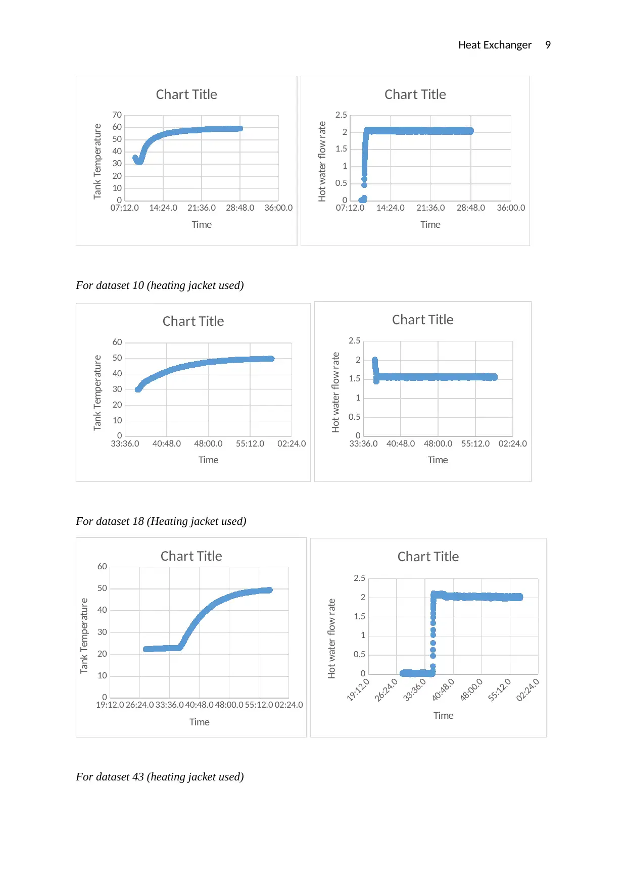
For dataset 10 (heating jacket used)
33:36.0 40:48.0 48:00.0 55:12.0 02:24.0
0
10
20
30
40
50
60
Chart Title
Time
Tank Temperature
33:36.0 40:48.0 48:00.0 55:12.0 02:24.0
0
0.5
1
1.5
2
2.5
Chart Title
Time
Hot water flow rate
For dataset 18 (Heating jacket used)
19:12.0 26:24.0 33:36.0 40:48.0 48:00.0 55:12.0 02:24.0
0
10
20
30
40
50
60 Chart Title
Time
Tank Temperature
19:12.0
26:24.0
33:36.0
40:48.0
48:00.0
55:12.0
02:24.0
0
0.5
1
1.5
2
2.5
Chart Title
Time
Hot water flow rate
For dataset 43 (heating jacket used)
07:12.0 14:24.0 21:36.0 28:48.0 36:00.0
0
10
20
30
40
50
60
70
Chart Title
Time
Tank Temperature
07:12.0 14:24.0 21:36.0 28:48.0 36:00.0
0
0.5
1
1.5
2
2.5
Chart Title
Time
Hot water flow rate
For dataset 10 (heating jacket used)
33:36.0 40:48.0 48:00.0 55:12.0 02:24.0
0
10
20
30
40
50
60
Chart Title
Time
Tank Temperature
33:36.0 40:48.0 48:00.0 55:12.0 02:24.0
0
0.5
1
1.5
2
2.5
Chart Title
Time
Hot water flow rate
For dataset 18 (Heating jacket used)
19:12.0 26:24.0 33:36.0 40:48.0 48:00.0 55:12.0 02:24.0
0
10
20
30
40
50
60 Chart Title
Time
Tank Temperature
19:12.0
26:24.0
33:36.0
40:48.0
48:00.0
55:12.0
02:24.0
0
0.5
1
1.5
2
2.5
Chart Title
Time
Hot water flow rate
For dataset 43 (heating jacket used)
⊘ This is a preview!⊘
Do you want full access?
Subscribe today to unlock all pages.
Trusted by 1+ million students worldwide
Heat Exchanger 10
26:24.0 33:36.0 40:48.0 48:00.0 55:12.0
0
10
20
30
40
50
60
Chart Title
Time
Tank Temperature
26:24.0 33:36.0 40:48.0 48:00.0 55:12.0
0
0.5
1
1.5
2
2.5
3
Chart Title
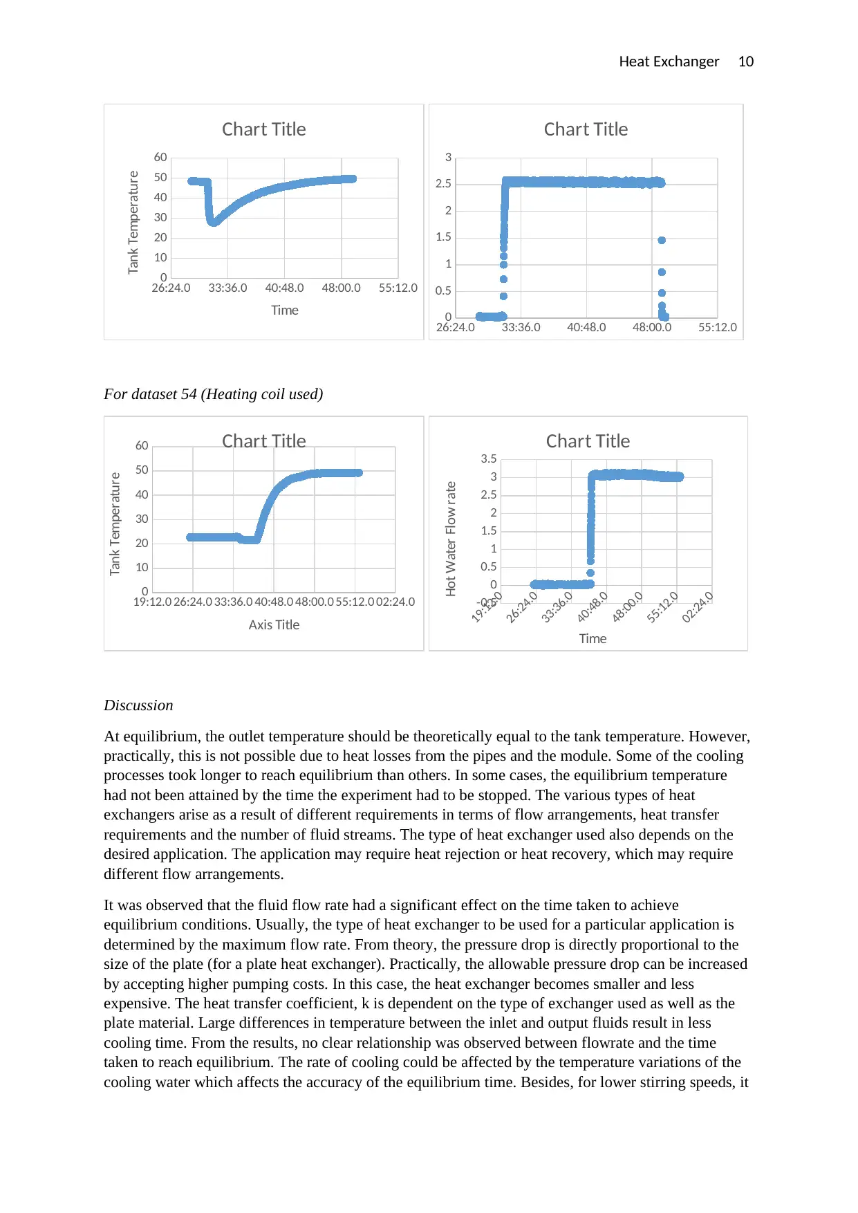
For dataset 54 (Heating coil used)
19:12.0 26:24.0 33:36.0 40:48.0 48:00.0 55:12.0 02:24.0
0
10
20
30
40
50
60 Chart Title
Axis Title
Tank Temperature
19:12.0
26:24.0
33:36.0
40:48.0
48:00.0
55:12.0
02:24.0
-0.5
0
0.5
1
1.5
2
2.5
3
3.5
Chart Title
Time
Hot Water Flow rate
Discussion
At equilibrium, the outlet temperature should be theoretically equal to the tank temperature. However,
practically, this is not possible due to heat losses from the pipes and the module. Some of the cooling
processes took longer to reach equilibrium than others. In some cases, the equilibrium temperature
had not been attained by the time the experiment had to be stopped. The various types of heat
exchangers arise as a result of different requirements in terms of flow arrangements, heat transfer
requirements and the number of fluid streams. The type of heat exchanger used also depends on the
desired application. The application may require heat rejection or heat recovery, which may require
different flow arrangements.
It was observed that the fluid flow rate had a significant effect on the time taken to achieve
equilibrium conditions. Usually, the type of heat exchanger to be used for a particular application is
determined by the maximum flow rate. From theory, the pressure drop is directly proportional to the
size of the plate (for a plate heat exchanger). Practically, the allowable pressure drop can be increased
by accepting higher pumping costs. In this case, the heat exchanger becomes smaller and less
expensive. The heat transfer coefficient, k is dependent on the type of exchanger used as well as the
plate material. Large differences in temperature between the inlet and output fluids result in less
cooling time. From the results, no clear relationship was observed between flowrate and the time
taken to reach equilibrium. The rate of cooling could be affected by the temperature variations of the
cooling water which affects the accuracy of the equilibrium time. Besides, for lower stirring speeds, it
26:24.0 33:36.0 40:48.0 48:00.0 55:12.0
0
10
20
30
40
50
60
Chart Title
Time
Tank Temperature
26:24.0 33:36.0 40:48.0 48:00.0 55:12.0
0
0.5
1
1.5
2
2.5
3
Chart Title
For dataset 54 (Heating coil used)
19:12.0 26:24.0 33:36.0 40:48.0 48:00.0 55:12.0 02:24.0
0
10
20
30
40
50
60 Chart Title
Axis Title
Tank Temperature
19:12.0
26:24.0
33:36.0
40:48.0
48:00.0
55:12.0
02:24.0
-0.5
0
0.5
1
1.5
2
2.5
3
3.5
Chart Title
Time
Hot Water Flow rate
Discussion
At equilibrium, the outlet temperature should be theoretically equal to the tank temperature. However,
practically, this is not possible due to heat losses from the pipes and the module. Some of the cooling
processes took longer to reach equilibrium than others. In some cases, the equilibrium temperature
had not been attained by the time the experiment had to be stopped. The various types of heat
exchangers arise as a result of different requirements in terms of flow arrangements, heat transfer
requirements and the number of fluid streams. The type of heat exchanger used also depends on the
desired application. The application may require heat rejection or heat recovery, which may require
different flow arrangements.
It was observed that the fluid flow rate had a significant effect on the time taken to achieve
equilibrium conditions. Usually, the type of heat exchanger to be used for a particular application is
determined by the maximum flow rate. From theory, the pressure drop is directly proportional to the
size of the plate (for a plate heat exchanger). Practically, the allowable pressure drop can be increased
by accepting higher pumping costs. In this case, the heat exchanger becomes smaller and less
expensive. The heat transfer coefficient, k is dependent on the type of exchanger used as well as the
plate material. Large differences in temperature between the inlet and output fluids result in less
cooling time. From the results, no clear relationship was observed between flowrate and the time
taken to reach equilibrium. The rate of cooling could be affected by the temperature variations of the
cooling water which affects the accuracy of the equilibrium time. Besides, for lower stirring speeds, it
Paraphrase This Document
Need a fresh take? Get an instant paraphrase of this document with our AI Paraphraser

Heat Exchanger 11
is difficult to maintain a steady rotation speed which also affects the results from one experiment to
another. Additional errors arise from human improper or inconsistent collection of data. For instance,
one of the data sets had an equilibrium time of 0.59 minutes which appeared inconsistent with the
other readings.
Conclusion
In conclusion, the conditions affecting the cooling rate of a fluid inside a heat exchanger were
successfully investigated. The variables identified as critical in the design of heat exchangers include
the fluid flow rate, the temperature difference between the two fluid streams and the configuration of
the flow.
Heat Exchanger 12
References
Chidambaram, M. (2018). Mathematical Modelling and Simulation in Chemical Engineering.
Cambridge, FL: Cambridge University Press.
Kakaç, S., Liu, H., & Pramuanjaroenkij, A. (2012). Heat Exchangers: Selection, Rating, and Thermal
Design, Third Edition. Boca Raton, FL: CRC Press.
Liu, J. (2017). The classification of the heat exchangers and theory research. doi:10.1063/1.4982393
Martin, H. (2010). N6 Pressure Drop and Heat Transfer in Plate Heat Exchangers. VDI Heat Atlas,
1515-1522. doi:10.1007/978-3-540-77877-6_109
Pressure Drop Across Plate Heat Exchangers. (2017). Low Grade Heat Driven Multi-Effect
Distillation and Desalination, 169-170. doi:10.1016/b978-0-12-805124-5.15003-x
Rathore, M. M., & Kapuno, R. R. (2011). Engineering Heat Transfer. Burlington, MA: Jones &
Bartlett Learning.
Thulukkanam, K. (2013). Heat Exchanger Design Handbook, Second Edition. Boca Raton, FL: CRC
Press.
⊘ This is a preview!⊘
Do you want full access?
Subscribe today to unlock all pages.
Trusted by 1+ million students worldwide
1 out of 12
Related Documents


Your All-in-One AI-Powered Toolkit for Academic Success.
+13062052269
info@desklib.com
Available 24*7 on WhatsApp / Email
![[object Object]](/_next/static/media/star-bottom.7253800d.svg)
Unlock your academic potential
Copyright © 2020–2025 A2Z Services. All Rights Reserved. Developed and managed by ZUCOL.