ENCOR 4010 - High-Density Fluids & CNT in Heat Exchanger Designs
VerifiedAdded on 2023/06/12
|21
|4413
|93
Literature Review
AI Summary
This literature review evaluates heat exchanger designs incorporating high-density fluids and carbon nanotubes (CNTs) to enhance thermal performance. It examines CNT membrane-based total heat exchangers, highlighting their advantages such as reduced weight and size, higher thermal exchange efficiency, and applications in various industries. The review discusses experimental setups and results, demonstrating the superior heat transfer performance of CNT composite membranes compared to commercial alternatives. It also explores CFD analysis of CNT nanofluids in transformers, emphasizing their potential to improve heat dissipation. The review concludes that CNTs offer significant advantages in heat exchanger design due to their unique thermal properties and potential for energy savings.
HEAT EXCHANGERS USING HIGH-DENSITY FLUIDS AND CNT
Name of Student
Institution Affiliation
HEAT EXCHANGERS USING HIGH-DENSITY FLUIDS AND CNT 1
Name of Student
Institution Affiliation
HEAT EXCHANGERS USING HIGH-DENSITY FLUIDS AND CNT 1
Paraphrase This Document
Need a fresh take? Get an instant paraphrase of this document with our AI Paraphraser
RESEARCH METHODOLOGY
Literature review
Topic
Evaluating designs of a heat exchanger with high-density fluids and carbon nanotube.
1. Abstract
This is an analytical approach to evaluate various designs of a heat exchanger with high-
density fluid and carbon nanotube. The thermal performance of high-density fluid and the carbon
nanotube is good compared to other materials. This study digs deep into investigating the various
designs of carbon nanotube heat exchangers
2. Introduction
In order to cope with the environmental challenges and get better and efficient methods of
heat dissipation, it is necessary to adopt methods that can enable us to dissipate heat efficiently.
The introduction of the heat exchangers and other energy recovery devices has then proven to be
the unavoidable choice to reduce consumption of energy. Carbon nanotubes total heat
exchangers is the new focus due to its rare advantages. The heat transfer performance of the
carbon nanotube (CNT) directly and positively affects the performance of the total heat
exchanger. Recent research and studies show that CNT carries better thermal conductivity as
well as faster moisture transferability. Thus, studying heat transfer characteristics of carbon
nanotube shall offer a primary data for the application of CNT based materials in total heat
exchangers.
2.1. Advantages and disadvantages
● They help to reduce the weight of the heat exchanger
HEAT EXCHANGERS USING HIGH-DENSITY FLUIDS AND CNT 2

● They help to reduce the size of the heat exchanger.
● They have a higher thermal exchange efficiency
● The surface area of the heat exchanger system, as well as the frontal loading, can be
reduced in size due to the small size of carbon nanotubes.
2.2. Applications
● They can be used in the automobile industry
● They can be used in fuel cells
● They can be applied in military radar and laser systems
● They can be used in power generation, transmission and distribution systems, for instance
in solar thermal generators, biofuel processing, petroleum refining, and industrial
processing amongst others (Yu et al, 2018).
3. Various designs of the heat exchanger with high-density fluids and carbon nanotube.
3.1 CNT membrane-based total heat exchanger
3.1.1 Introduction
The total heat exchanger is the core component of any fresh air energy recovery system.
Currently, there exist three main types including the wheel type, the heat-pipe type, and the
fixed-plate type. The wheel type is the most broadly used type of heat recovery device. However,
it is prone to leaking and requires a lot of maintenance. In the recent past, energy recovery
systems that are membrane-based have caught the attention of many people due to zero air
leakage, simple system and characteristics of anti-icing (Chen et al, 2016).
This study of the heat exchanger concentrates on improving the rate of saving energy by
the ventilation system, studying the parameters affecting the system as well as examining the
HEAT EXCHANGERS USING HIGH-DENSITY FLUIDS AND CNT 3
⊘ This is a preview!⊘
Do you want full access?
Subscribe today to unlock all pages.
Trusted by 1+ million students worldwide
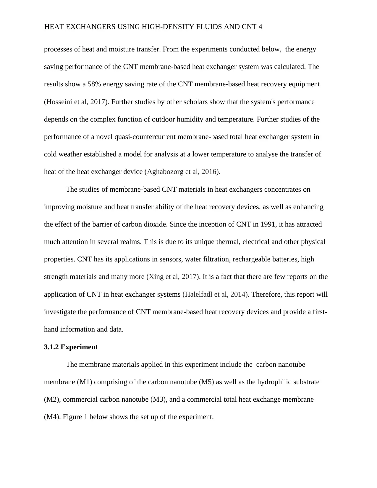
processes of heat and moisture transfer. From the experiments conducted below, the energy
saving performance of the CNT membrane-based heat exchanger system was calculated. The
results show a 58% energy saving rate of the CNT membrane-based heat recovery equipment
(Hosseini et al, 2017). Further studies by other scholars show that the system's performance
depends on the complex function of outdoor humidity and temperature. Further studies of the
performance of a novel quasi-countercurrent membrane-based total heat exchanger system in
cold weather established a model for analysis at a lower temperature to analyse the transfer of
heat of the heat exchanger device (Aghabozorg et al, 2016).
The studies of membrane-based CNT materials in heat exchangers concentrates on
improving moisture and heat transfer ability of the heat recovery devices, as well as enhancing
the effect of the barrier of carbon dioxide. Since the inception of CNT in 1991, it has attracted
much attention in several realms. This is due to its unique thermal, electrical and other physical
properties. CNT has its applications in sensors, water filtration, rechargeable batteries, high
strength materials and many more (Xing et al, 2017). It is a fact that there are few reports on the
application of CNT in heat exchanger systems (Halelfadl et al, 2014). Therefore, this report will
investigate the performance of CNT membrane-based heat recovery devices and provide a first-
hand information and data.
3.1.2 Experiment
The membrane materials applied in this experiment include the carbon nanotube
membrane (M1) comprising of the carbon nanotube (M5) as well as the hydrophilic substrate
(M2), commercial carbon nanotube (M3), and a commercial total heat exchange membrane
(M4). Figure 1 below shows the set up of the experiment.
HEAT EXCHANGERS USING HIGH-DENSITY FLUIDS AND CNT 4
Paraphrase This Document
Need a fresh take? Get an instant paraphrase of this document with our AI Paraphraser
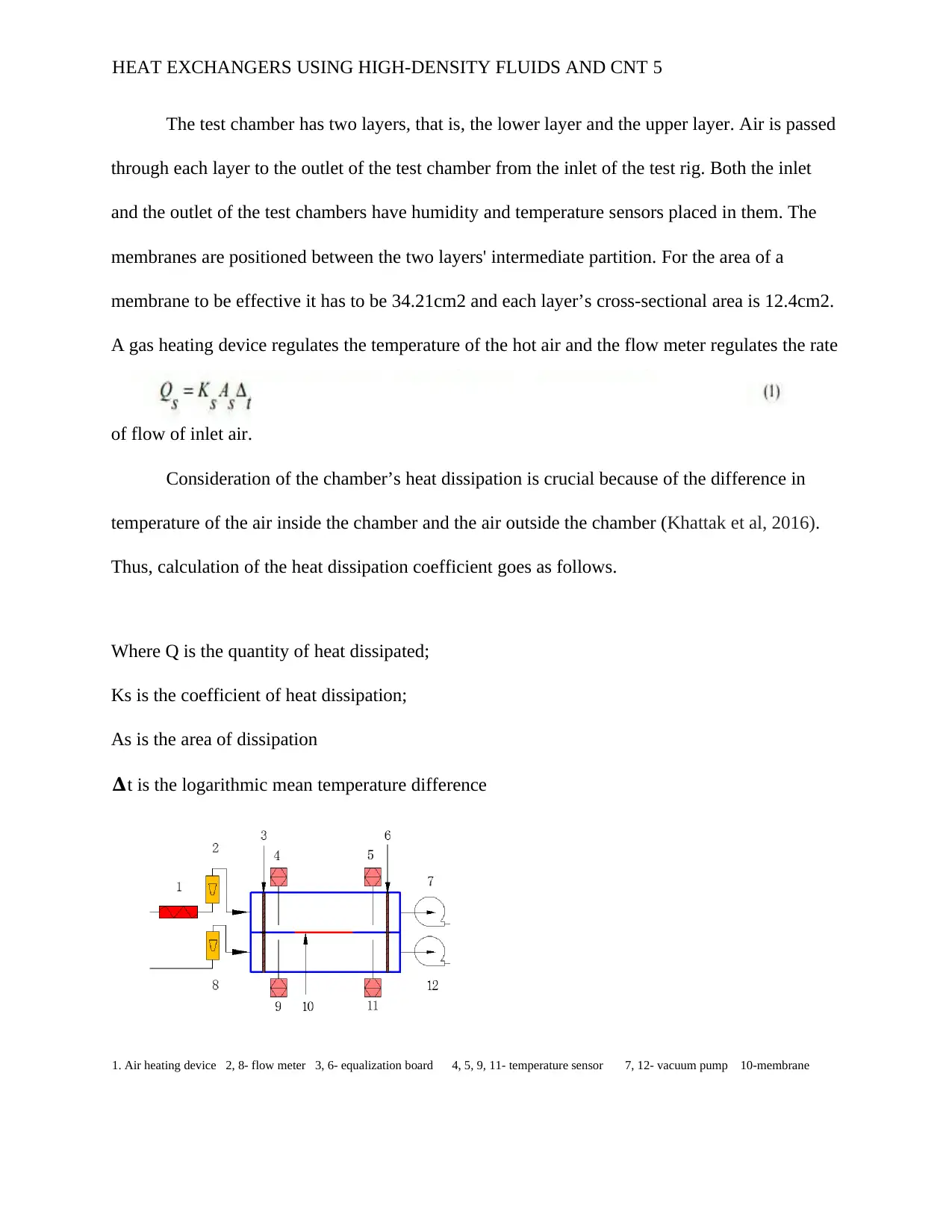
The test chamber has two layers, that is, the lower layer and the upper layer. Air is passed
through each layer to the outlet of the test chamber from the inlet of the test rig. Both the inlet
and the outlet of the test chambers have humidity and temperature sensors placed in them. The
membranes are positioned between the two layers' intermediate partition. For the area of a
membrane to be effective it has to be 34.21cm2 and each layer’s cross-sectional area is 12.4cm2.
A gas heating device regulates the temperature of the hot air and the flow meter regulates the rate
of flow of inlet air.
Consideration of the chamber’s heat dissipation is crucial because of the difference in
temperature of the air inside the chamber and the air outside the chamber (Khattak et al, 2016).
Thus, calculation of the heat dissipation coefficient goes as follows.
Where Q is the quantity of heat dissipated;
Ks is the coefficient of heat dissipation;
As is the area of dissipation
𝚫t is the logarithmic mean temperature difference
1. Air heating device 2, 8- flow meter 3, 6- equalization board 4, 5, 9, 11- temperature sensor 7, 12- vacuum pump 10-membrane
HEAT EXCHANGERS USING HIGH-DENSITY FLUIDS AND CNT 5
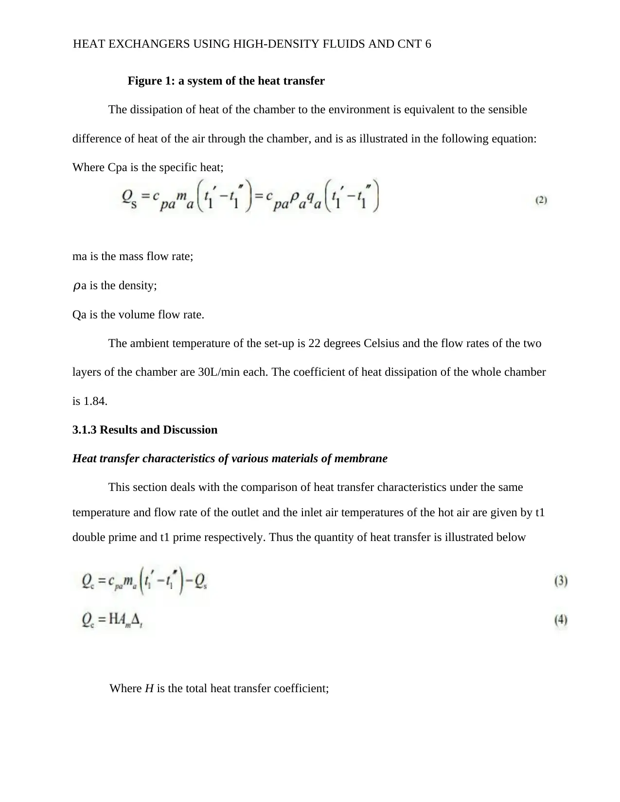
Figure 1: a system of the heat transfer
The dissipation of heat of the chamber to the environment is equivalent to the sensible
difference of heat of the air through the chamber, and is as illustrated in the following equation:
Where Cpa is the specific heat;
ma is the mass flow rate;
𝜌a is the density;
Qa is the volume flow rate.
The ambient temperature of the set-up is 22 degrees Celsius and the flow rates of the two
layers of the chamber are 30L/min each. The coefficient of heat dissipation of the whole chamber
is 1.84.
3.1.3 Results and Discussion
Heat transfer characteristics of various materials of membrane
This section deals with the comparison of heat transfer characteristics under the same
temperature and flow rate of the outlet and the inlet air temperatures of the hot air are given by t1
double prime and t1 prime respectively. Thus the quantity of heat transfer is illustrated below
Where H is the total heat transfer coefficient;
HEAT EXCHANGERS USING HIGH-DENSITY FLUIDS AND CNT 6
⊘ This is a preview!⊘
Do you want full access?
Subscribe today to unlock all pages.
Trusted by 1+ million students worldwide
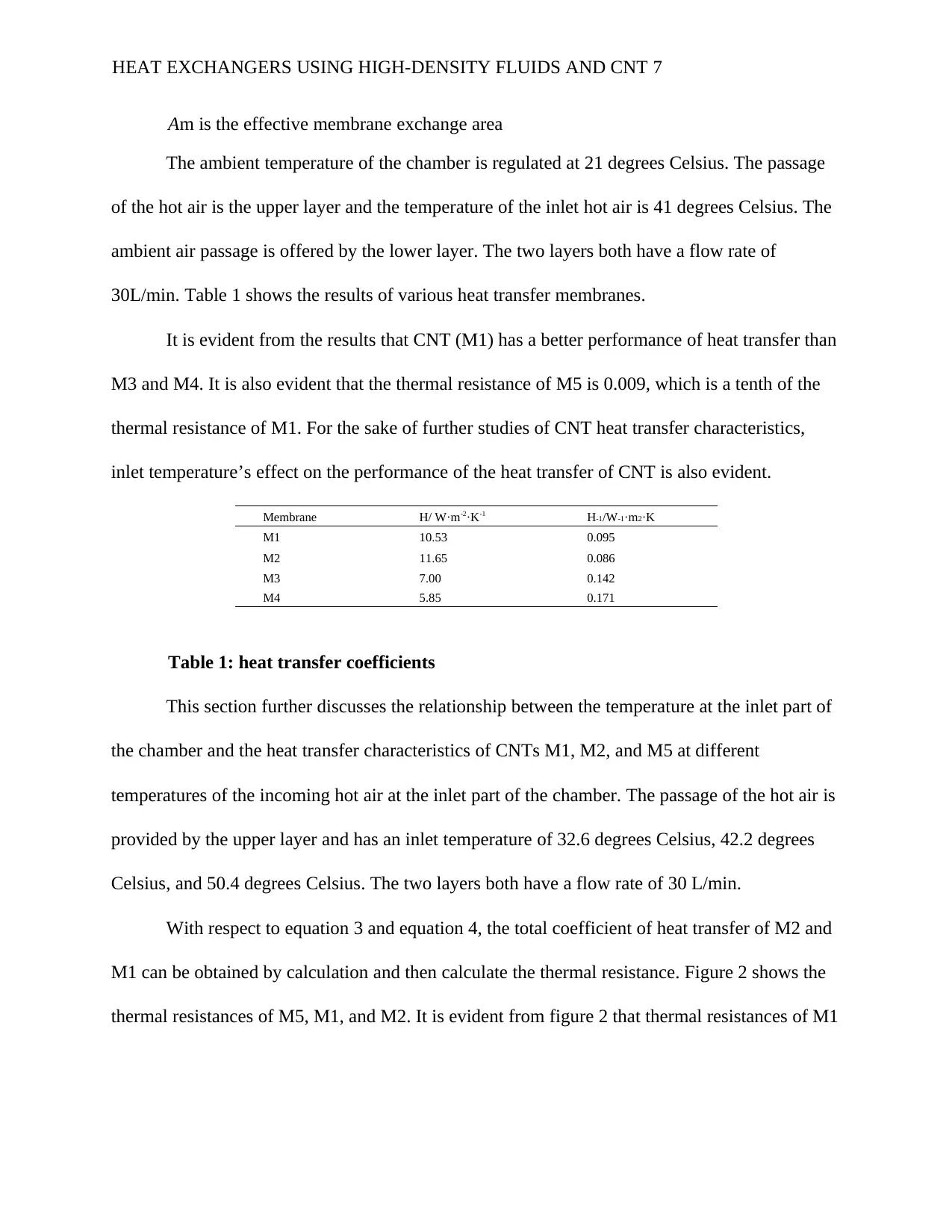
Am is the effective membrane exchange area
The ambient temperature of the chamber is regulated at 21 degrees Celsius. The passage
of the hot air is the upper layer and the temperature of the inlet hot air is 41 degrees Celsius. The
ambient air passage is offered by the lower layer. The two layers both have a flow rate of
30L/min. Table 1 shows the results of various heat transfer membranes.
It is evident from the results that CNT (M1) has a better performance of heat transfer than
M3 and M4. It is also evident that the thermal resistance of M5 is 0.009, which is a tenth of the
thermal resistance of M1. For the sake of further studies of CNT heat transfer characteristics,
inlet temperature’s effect on the performance of the heat transfer of CNT is also evident.
Membrane H/ W·m-2·K-1 H-1/W-1·m2·K
M1 10.53 0.095
M2 11.65 0.086
M3 7.00 0.142
M4 5.85 0.171
Table 1: heat transfer coefficients
This section further discusses the relationship between the temperature at the inlet part of
the chamber and the heat transfer characteristics of CNTs M1, M2, and M5 at different
temperatures of the incoming hot air at the inlet part of the chamber. The passage of the hot air is
provided by the upper layer and has an inlet temperature of 32.6 degrees Celsius, 42.2 degrees
Celsius, and 50.4 degrees Celsius. The two layers both have a flow rate of 30 L/min.
With respect to equation 3 and equation 4, the total coefficient of heat transfer of M2 and
M1 can be obtained by calculation and then calculate the thermal resistance. Figure 2 shows the
thermal resistances of M5, M1, and M2. It is evident from figure 2 that thermal resistances of M1
HEAT EXCHANGERS USING HIGH-DENSITY FLUIDS AND CNT 7
Paraphrase This Document
Need a fresh take? Get an instant paraphrase of this document with our AI Paraphraser
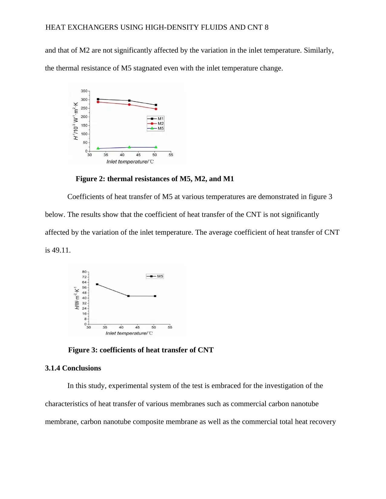
and that of M2 are not significantly affected by the variation in the inlet temperature. Similarly,
the thermal resistance of M5 stagnated even with the inlet temperature change.
Figure 2: thermal resistances of M5, M2, and M1
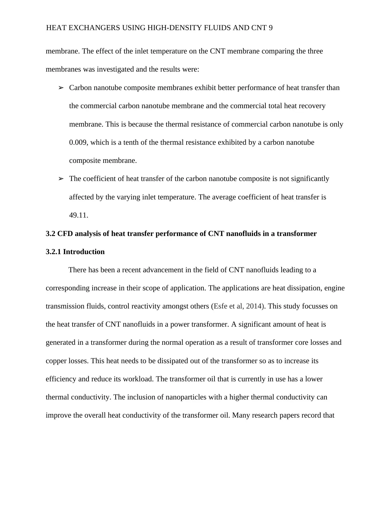
Coefficients of heat transfer of M5 at various temperatures are demonstrated in figure 3
below. The results show that the coefficient of heat transfer of the CNT is not significantly
affected by the variation of the inlet temperature. The average coefficient of heat transfer of CNT
is 49.11.
Figure 3: coefficients of heat transfer of CNT
3.1.4 Conclusions
In this study, experimental system of the test is embraced for the investigation of the
characteristics of heat transfer of various membranes such as commercial carbon nanotube
membrane, carbon nanotube composite membrane as well as the commercial total heat recovery
HEAT EXCHANGERS USING HIGH-DENSITY FLUIDS AND CNT 8
the thermal resistance of M5 stagnated even with the inlet temperature change.
Figure 2: thermal resistances of M5, M2, and M1
Coefficients of heat transfer of M5 at various temperatures are demonstrated in figure 3
below. The results show that the coefficient of heat transfer of the CNT is not significantly
affected by the variation of the inlet temperature. The average coefficient of heat transfer of CNT
is 49.11.
Figure 3: coefficients of heat transfer of CNT
3.1.4 Conclusions
In this study, experimental system of the test is embraced for the investigation of the
characteristics of heat transfer of various membranes such as commercial carbon nanotube
membrane, carbon nanotube composite membrane as well as the commercial total heat recovery
HEAT EXCHANGERS USING HIGH-DENSITY FLUIDS AND CNT 8
membrane. The effect of the inlet temperature on the CNT membrane comparing the three
membranes was investigated and the results were:
➢ Carbon nanotube composite membranes exhibit better performance of heat transfer than
the commercial carbon nanotube membrane and the commercial total heat recovery
membrane. This is because the thermal resistance of commercial carbon nanotube is only
0.009, which is a tenth of the thermal resistance exhibited by a carbon nanotube
composite membrane.
➢ The coefficient of heat transfer of the carbon nanotube composite is not significantly
affected by the varying inlet temperature. The average coefficient of heat transfer is
49.11.
3.2 CFD analysis of heat transfer performance of CNT nanofluids in a transformer
3.2.1 Introduction
There has been a recent advancement in the field of CNT nanofluids leading to a
corresponding increase in their scope of application. The applications are heat dissipation, engine
transmission fluids, control reactivity amongst others (Esfe et al, 2014). This study focusses on
the heat transfer of CNT nanofluids in a power transformer. A significant amount of heat is
generated in a transformer during the normal operation as a result of transformer core losses and
copper losses. This heat needs to be dissipated out of the transformer so as to increase its
efficiency and reduce its workload. The transformer oil that is currently in use has a lower
thermal conductivity. The inclusion of nanoparticles with a higher thermal conductivity can
improve the overall heat conductivity of the transformer oil. Many research papers record that
HEAT EXCHANGERS USING HIGH-DENSITY FLUIDS AND CNT 9
⊘ This is a preview!⊘
Do you want full access?
Subscribe today to unlock all pages.
Trusted by 1+ million students worldwide
addition of engineered nanoparticles enhances the thermal performance of the conventional
transformer oil (Huang et al, 2016).
There are limited research studies on the use of nanofluids in the transformer world.
Studies show that mass flow rate fluctuation in vertical channels occurs as a result of flow in the
horizontal channels (Goodarzi et al, 2015). This concludes that coefficient of heat transfer
depends on the Reynolds number and Grashof number. Studies of the behavior of heat in a 3-
phase transformer using a 3-D finite volume method show that forced convection by water has
better heat transfer characteristics than natural air convection for cases dry-type (Huminic &
Huminic (2016)).
CFD simulations were performed using a sliced model to study the thermal performance
of an (ONAN) distributor transformer. Velocity and temperature profiles were investigated at
various conditions and the pattern of fluid flow was realised to be similar in all scenarios
(Knowles et al, 2015). In another study where such parameters as temperature change
distribution, electrophoresis, and velocity distribution were examined using silicon carbide
nanofluids, it was found out that the heat performance of the transformer oil greatly and
significantly improved. This was due to the addition of the nanofluids (Ellahi et al, 2015).
Numerical simulations are carried out in a model of a distributor transformer filled with
oil for investigating effects of transport and flow of fluid at different concentrations of
nanoparticles. 3-D CFD simulations on two different nanofluid systems to examine heat transfer
by natural convection. The overall effect on heat transfer performance is approximated and a
comparison made with a base fluid which is the transformer oil. Nusselt number, overall
coefficient of heat transfer and Rayleigh number are approximated at various particles loading to
HEAT EXCHANGERS USING HIGH-DENSITY FLUIDS AND CNT 10
Paraphrase This Document
Need a fresh take? Get an instant paraphrase of this document with our AI Paraphraser
examine the nanoparticle concentration effect on the performance of heat transfer in the model
(Wu et al, 2016).
3.2.2 Experiment
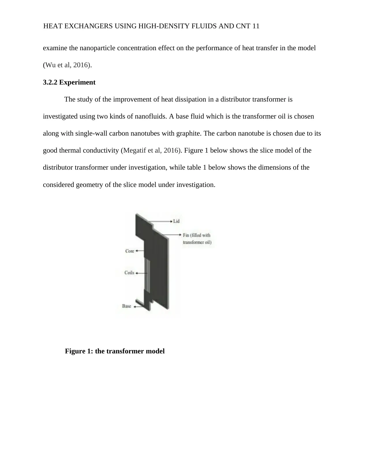
The study of the improvement of heat dissipation in a distributor transformer is
investigated using two kinds of nanofluids. A base fluid which is the transformer oil is chosen
along with single-wall carbon nanotubes with graphite. The carbon nanotube is chosen due to its
good thermal conductivity (Megatif et al, 2016). Figure 1 below shows the slice model of the
distributor transformer under investigation, while table 1 below shows the dimensions of the
considered geometry of the slice model under investigation.
Figure 1: the transformer model
HEAT EXCHANGERS USING HIGH-DENSITY FLUIDS AND CNT 11
(Wu et al, 2016).
3.2.2 Experiment
The study of the improvement of heat dissipation in a distributor transformer is
investigated using two kinds of nanofluids. A base fluid which is the transformer oil is chosen
along with single-wall carbon nanotubes with graphite. The carbon nanotube is chosen due to its
good thermal conductivity (Megatif et al, 2016). Figure 1 below shows the slice model of the
distributor transformer under investigation, while table 1 below shows the dimensions of the
considered geometry of the slice model under investigation.
Figure 1: the transformer model
HEAT EXCHANGERS USING HIGH-DENSITY FLUIDS AND CNT 11
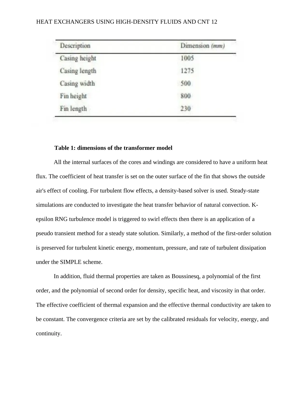
Table 1: dimensions of the transformer model
All the internal surfaces of the cores and windings are considered to have a uniform heat
flux. The coefficient of heat transfer is set on the outer surface of the fin that shows the outside
air's effect of cooling. For turbulent flow effects, a density-based solver is used. Steady-state
simulations are conducted to investigate the heat transfer behavior of natural convection. K-
epsilon RNG turbulence model is triggered to swirl effects then there is an application of a
pseudo transient method for a steady state solution. Similarly, a method of the first-order solution
is preserved for turbulent kinetic energy, momentum, pressure, and rate of turbulent dissipation
under the SIMPLE scheme.
In addition, fluid thermal properties are taken as Boussinesq, a polynomial of the first
order, and the polynomial of second order for density, specific heat, and viscosity in that order.
The effective coefficient of thermal expansion and the effective thermal conductivity are taken to
be constant. The convergence criteria are set by the calibrated residuals for velocity, energy, and
continuity.
HEAT EXCHANGERS USING HIGH-DENSITY FLUIDS AND CNT 12
⊘ This is a preview!⊘
Do you want full access?
Subscribe today to unlock all pages.
Trusted by 1+ million students worldwide
1 out of 21
Related Documents


Your All-in-One AI-Powered Toolkit for Academic Success.
+13062052269
info@desklib.com
Available 24*7 on WhatsApp / Email
![[object Object]](/_next/static/media/star-bottom.7253800d.svg)
Unlock your academic potential
Copyright © 2020–2026 A2Z Services. All Rights Reserved. Developed and managed by ZUCOL.