ENGT 5146 Building Physics: Maximizing Sunlight & Avoiding Overheating
VerifiedAdded on 2023/05/28
|15
|3781
|494
Report
AI Summary
This report provides a detailed analysis of heat gain in buildings, focusing on potential sources like appliances, windows, walls, leaks, ceilings, and attics. It includes calculations for heat gain through glass windows, appliances, occupancy, and infiltration, with specific examples for rooms F-6, F-7, F-14, F-15, F-16, F-18, and F-22. The report calculates heat gain per floor area for Edinburgh, considering internal and external conditions, and examines varied orientations in Manchester, evaluating heat transfer rates via walls, roofs, and floors. It further assesses heat transfer rates in SW, SE, and NW orientations, analyzing sensible and latent heat loads, and determines the required cooling capacity using a safety factor. The report concludes with a discussion on lightweight versus heavyweight construction materials for summer heat gain control, highlighting the impact of material choices on building thermal performance.
BUILDING PHYSICS
By Name
Course
Instructor
Institution
Location
Date
By Name
Course
Instructor
Institution
Location
Date
Paraphrase This Document
Need a fresh take? Get an instant paraphrase of this document with our AI Paraphraser
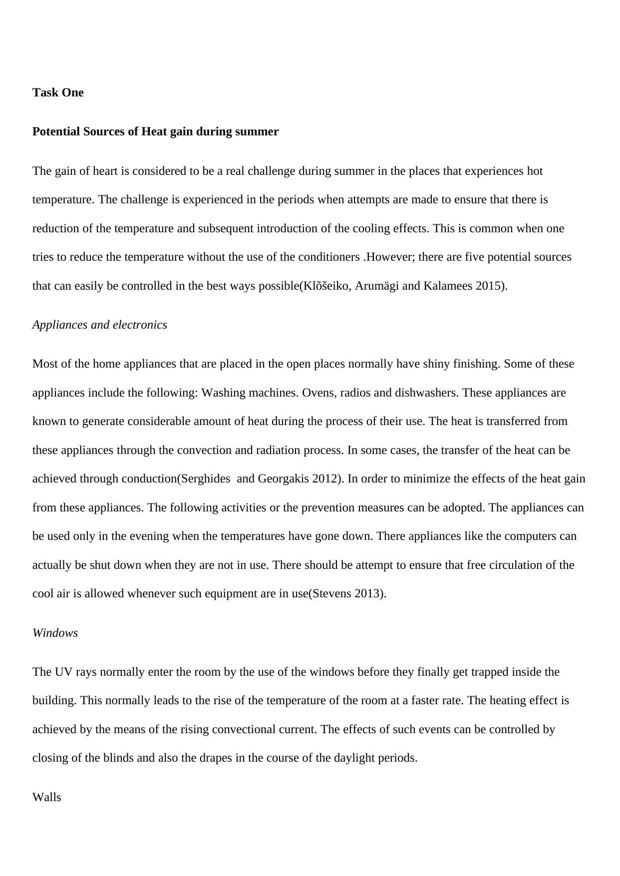
Task One
Potential Sources of Heat gain during summer
The gain of heart is considered to be a real challenge during summer in the places that experiences hot
temperature. The challenge is experienced in the periods when attempts are made to ensure that there is
reduction of the temperature and subsequent introduction of the cooling effects. This is common when one
tries to reduce the temperature without the use of the conditioners .However; there are five potential sources
that can easily be controlled in the best ways possible(Klõšeiko, Arumägi and Kalamees 2015).
Appliances and electronics
Most of the home appliances that are placed in the open places normally have shiny finishing. Some of these
appliances include the following: Washing machines. Ovens, radios and dishwashers. These appliances are
known to generate considerable amount of heat during the process of their use. The heat is transferred from
these appliances through the convection and radiation process. In some cases, the transfer of the heat can be
achieved through conduction(Serghides and Georgakis 2012). In order to minimize the effects of the heat gain
from these appliances. The following activities or the prevention measures can be adopted. The appliances can
be used only in the evening when the temperatures have gone down. There appliances like the computers can
actually be shut down when they are not in use. There should be attempt to ensure that free circulation of the
cool air is allowed whenever such equipment are in use(Stevens 2013).
Windows
The UV rays normally enter the room by the use of the windows before they finally get trapped inside the
building. This normally leads to the rise of the temperature of the room at a faster rate. The heating effect is
achieved by the means of the rising convectional current. The effects of such events can be controlled by
closing of the blinds and also the drapes in the course of the daylight periods.
Walls
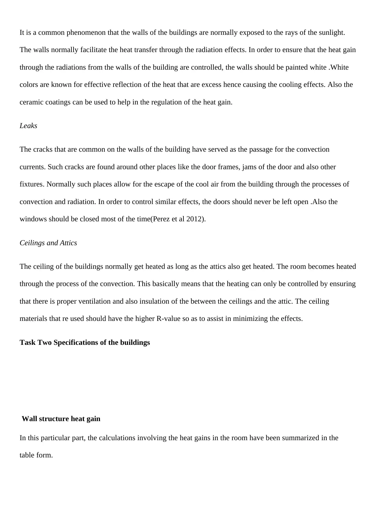
It is a common phenomenon that the walls of the buildings are normally exposed to the rays of the sunlight.
The walls normally facilitate the heat transfer through the radiation effects. In order to ensure that the heat gain
through the radiations from the walls of the building are controlled, the walls should be painted white .White
colors are known for effective reflection of the heat that are excess hence causing the cooling effects. Also the
ceramic coatings can be used to help in the regulation of the heat gain.
Leaks
The cracks that are common on the walls of the building have served as the passage for the convection
currents. Such cracks are found around other places like the door frames, jams of the door and also other
fixtures. Normally such places allow for the escape of the cool air from the building through the processes of
convection and radiation. In order to control similar effects, the doors should never be left open .Also the
windows should be closed most of the time(Perez et al 2012).
Ceilings and Attics
The ceiling of the buildings normally get heated as long as the attics also get heated. The room becomes heated
through the process of the convection. This basically means that the heating can only be controlled by ensuring
that there is proper ventilation and also insulation of the between the ceilings and the attic. The ceiling
materials that re used should have the higher R-value so as to assist in minimizing the effects.
Task Two Specifications of the buildings
Wall structure heat gain
In this particular part, the calculations involving the heat gains in the room have been summarized in the
table form.
⊘ This is a preview!⊘
Do you want full access?
Subscribe today to unlock all pages.
Trusted by 1+ million students worldwide
The
room
numbers
Quantity
of
Windows
facing
specific
points
Window
Area
(m2)
SHGF
Value
(W/m2)
Shading
coefficie
nt,
Heat
gain in
Watts
F-6 6 SE 2.178 470.25 0.95 5838
4 SW 2.178 470.25 0.95 3892
F-7 2 SE 2.178 470.25 0.95 1946
4 SW 2.178 470.25 0.95 3892
F-14 6 NW 2.178 520.5 0.95 6462
F-15 2 NE 2.178 520.5 0.95 2154
4 NW 2.178 520.5 0.95 4308
F-16 2 NE 2.178 520.5 0.95 2154
2 SW 2.178 470.25 0.95 1946
4 NW 2.178 520.5 0.95 4308
F-18 6 SW 2.178 470.25 0.95 5838
4 NW 2.178 520.5 0.95 4308
F-22 5 NE 2.178 520.5 0.95 5385
4 SE 2.178 470.25 0.95 3892
Total 56323
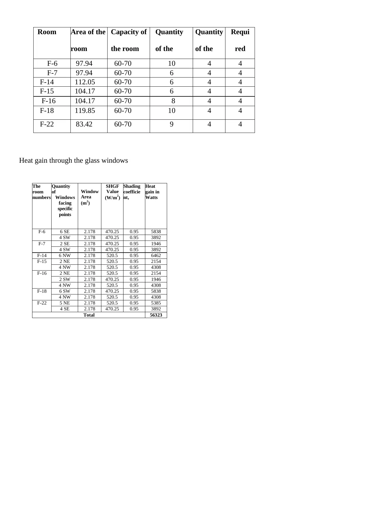
Room Area of the
room
Capacity of
the room
per person
Quantity
of the
windows
Quantity
of the
escalator
Requi
red
numbeF-6 97.94 60-70 10 4 4
F-7 97.94 60-70 6 4 4
F-14 112.05 60-70 6 4 4
F-15 104.17 60-70 6 4 4
F-16 104.17 60-70 8 4 4
F-18 119.85 60-70 10 4 4
F-22 83.42 60-70 9 4 4
Heat gain through the glass windows
room
numbers
Quantity
of
Windows
facing
specific
points
Window
Area
(m2)
SHGF
Value
(W/m2)
Shading
coefficie
nt,
Heat
gain in
Watts
F-6 6 SE 2.178 470.25 0.95 5838
4 SW 2.178 470.25 0.95 3892
F-7 2 SE 2.178 470.25 0.95 1946
4 SW 2.178 470.25 0.95 3892
F-14 6 NW 2.178 520.5 0.95 6462
F-15 2 NE 2.178 520.5 0.95 2154
4 NW 2.178 520.5 0.95 4308
F-16 2 NE 2.178 520.5 0.95 2154
2 SW 2.178 470.25 0.95 1946
4 NW 2.178 520.5 0.95 4308
F-18 6 SW 2.178 470.25 0.95 5838
4 NW 2.178 520.5 0.95 4308
F-22 5 NE 2.178 520.5 0.95 5385
4 SE 2.178 470.25 0.95 3892
Total 56323
Room Area of the
room
Capacity of
the room
per person
Quantity
of the
windows
Quantity
of the
escalator
Requi
red
numbeF-6 97.94 60-70 10 4 4
F-7 97.94 60-70 6 4 4
F-14 112.05 60-70 6 4 4
F-15 104.17 60-70 6 4 4
F-16 104.17 60-70 8 4 4
F-18 119.85 60-70 10 4 4
F-22 83.42 60-70 9 4 4
Heat gain through the glass windows
Paraphrase This Document
Need a fresh take? Get an instant paraphrase of this document with our AI Paraphraser
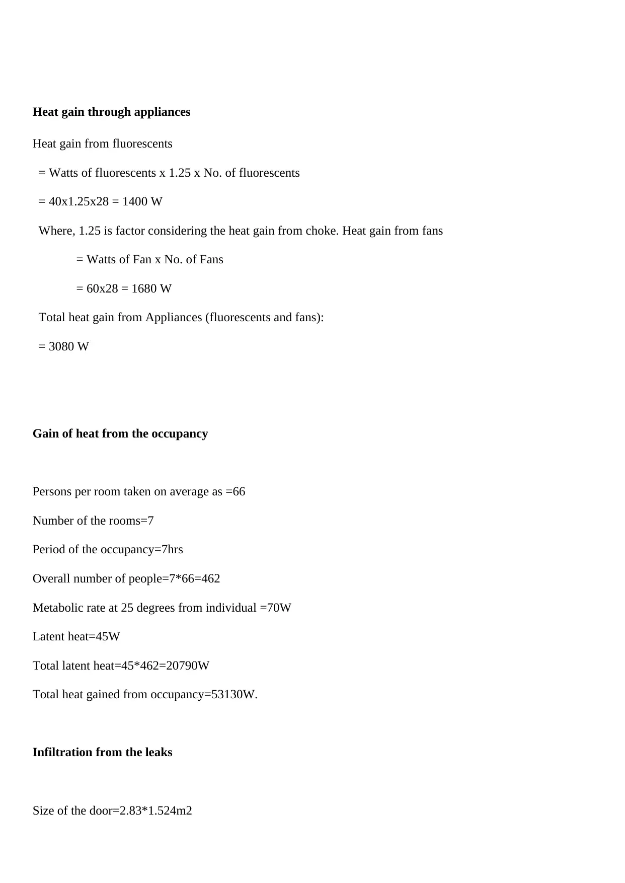
Heat gain through appliances
Heat gain from fluorescents
= Watts of fluorescents x 1.25 x No. of fluorescents
= 40x1.25x28 = 1400 W
Where, 1.25 is factor considering the heat gain from choke. Heat gain from fans
= Watts of Fan x No. of Fans
= 60x28 = 1680 W
Total heat gain from Appliances (fluorescents and fans):
= 3080 W
Gain of heat from the occupancy
Persons per room taken on average as =66
Number of the rooms=7
Period of the occupancy=7hrs
Overall number of people=7*66=462
Metabolic rate at 25 degrees from individual =70W
Latent heat=45W
Total latent heat=45*462=20790W
Total heat gained from occupancy=53130W.
Infiltration from the leaks
Size of the door=2.83*1.524m2
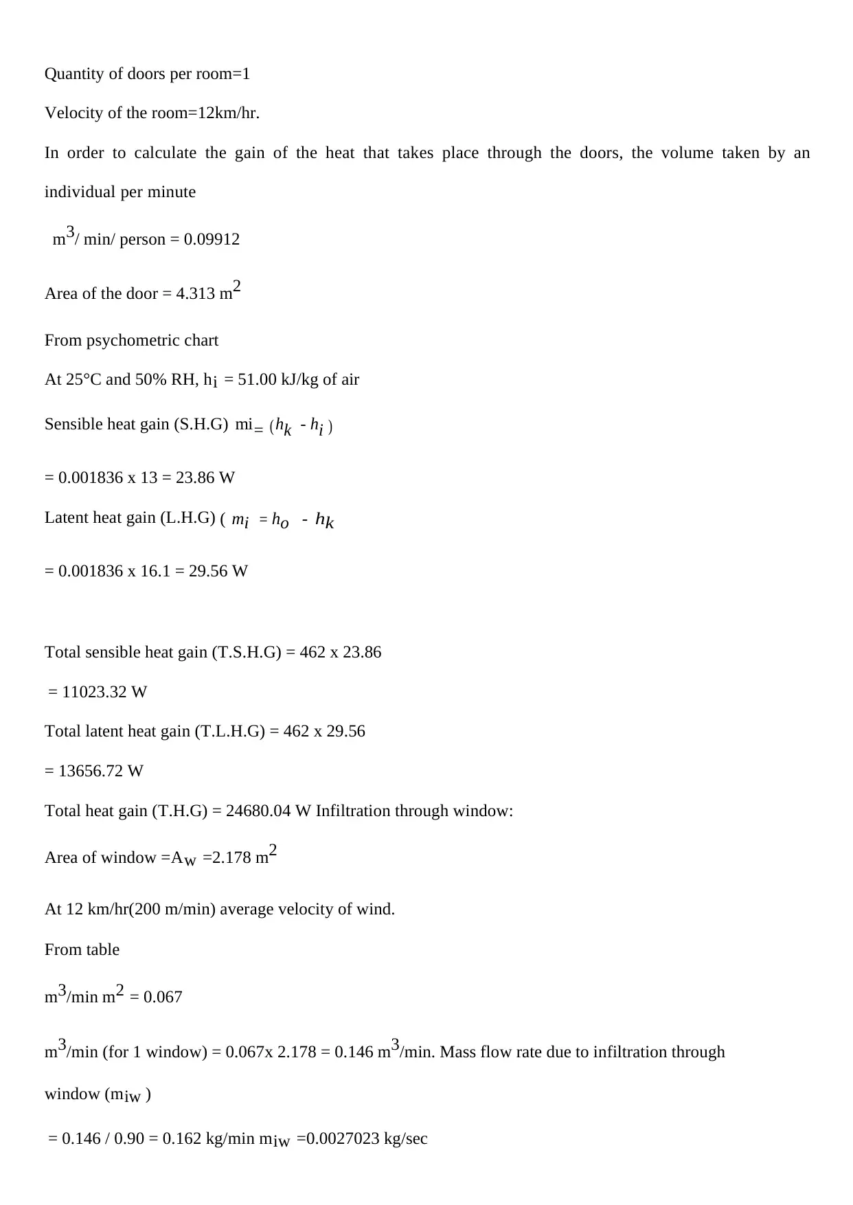
Quantity of doors per room=1
Velocity of the room=12km/hr.
In order to calculate the gain of the heat that takes place through the doors, the volume taken by an
individual per minute
m3/ min/ person = 0.09912
Area of the door = 4.313 m2
From psychometric chart
At 25°C and 50% RH, hi = 51.00 kJ/kg of air
Sensible heat gain (S.H.G) mi= ( hk - hi )
= 0.001836 x 13 = 23.86 W
Latent heat gain (L.H.G) ( mi = ho - h k
= 0.001836 x 16.1 = 29.56 W
Total sensible heat gain (T.S.H.G) = 462 x 23.86
= 11023.32 W
Total latent heat gain (T.L.H.G) = 462 x 29.56
= 13656.72 W
Total heat gain (T.H.G) = 24680.04 W Infiltration through window:
Area of window =Aw =2.178 m2
At 12 km/hr(200 m/min) average velocity of wind.
From table
m3/min m2 = 0.067
m3/min (for 1 window) = 0.067x 2.178 = 0.146 m3/min. Mass flow rate due to infiltration through
window (miw )
= 0.146 / 0.90 = 0.162 kg/min miw =0.0027023 kg/sec
⊘ This is a preview!⊘
Do you want full access?
Subscribe today to unlock all pages.
Trusted by 1+ million students worldwide
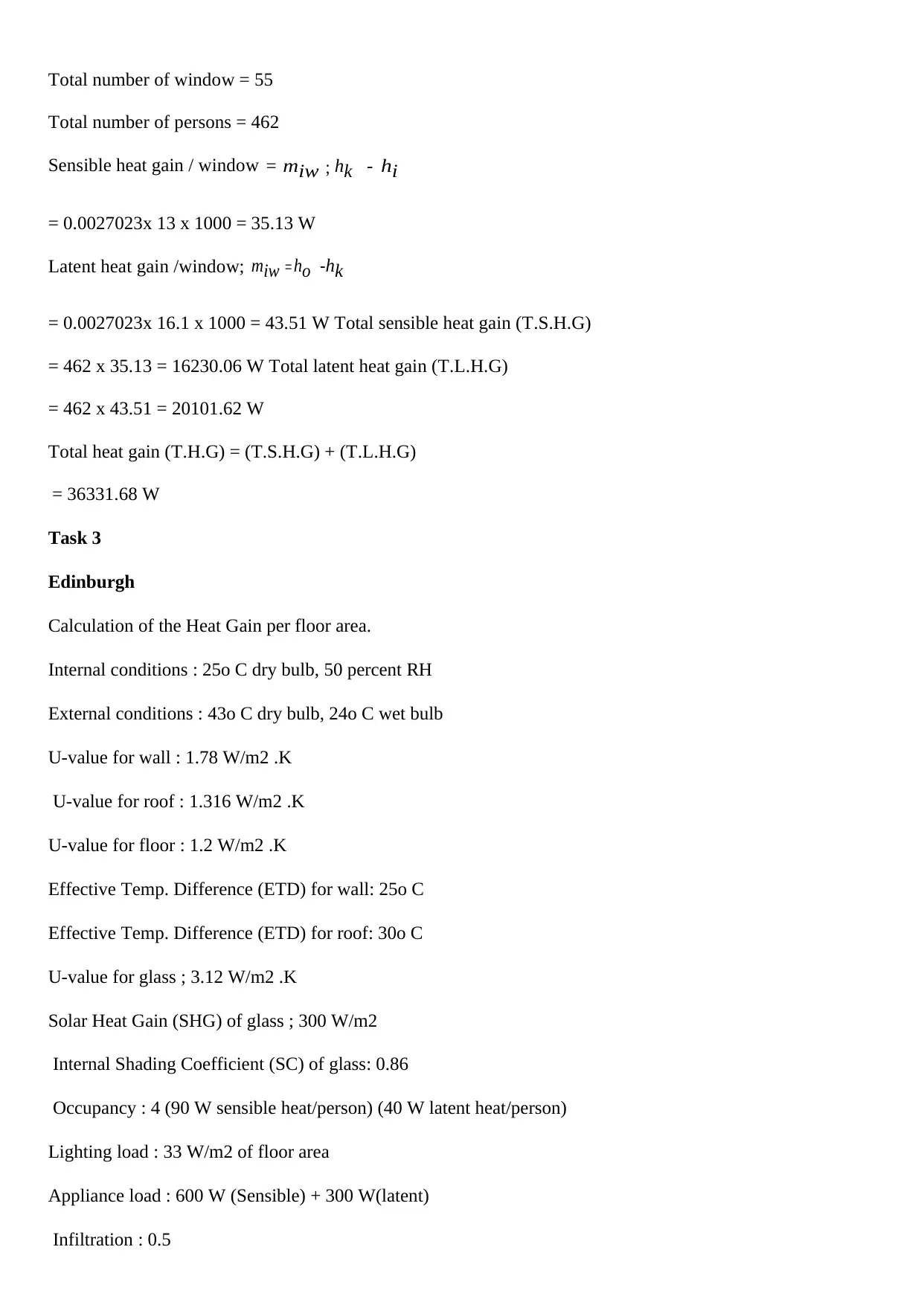
Total number of window = 55
Total number of persons = 462
Sensible heat gain / window = miw ; hk - h i
= 0.0027023x 13 x 1000 = 35.13 W
Latent heat gain /window; miw = ho -hk
= 0.0027023x 16.1 x 1000 = 43.51 W Total sensible heat gain (T.S.H.G)
= 462 x 35.13 = 16230.06 W Total latent heat gain (T.L.H.G)
= 462 x 43.51 = 20101.62 W
Total heat gain (T.H.G) = (T.S.H.G) + (T.L.H.G)
= 36331.68 W
Task 3
Edinburgh
Calculation of the Heat Gain per floor area.
Internal conditions : 25o C dry bulb, 50 percent RH
External conditions : 43o C dry bulb, 24o C wet bulb
U-value for wall : 1.78 W/m2 .K
U-value for roof : 1.316 W/m2 .K
U-value for floor : 1.2 W/m2 .K
Effective Temp. Difference (ETD) for wall: 25o C
Effective Temp. Difference (ETD) for roof: 30o C
U-value for glass ; 3.12 W/m2 .K
Solar Heat Gain (SHG) of glass ; 300 W/m2
Internal Shading Coefficient (SC) of glass: 0.86
Occupancy : 4 (90 W sensible heat/person) (40 W latent heat/person)
Lighting load : 33 W/m2 of floor area
Appliance load : 600 W (Sensible) + 300 W(latent)
Infiltration : 0.5
Paraphrase This Document
Need a fresh take? Get an instant paraphrase of this document with our AI Paraphraser
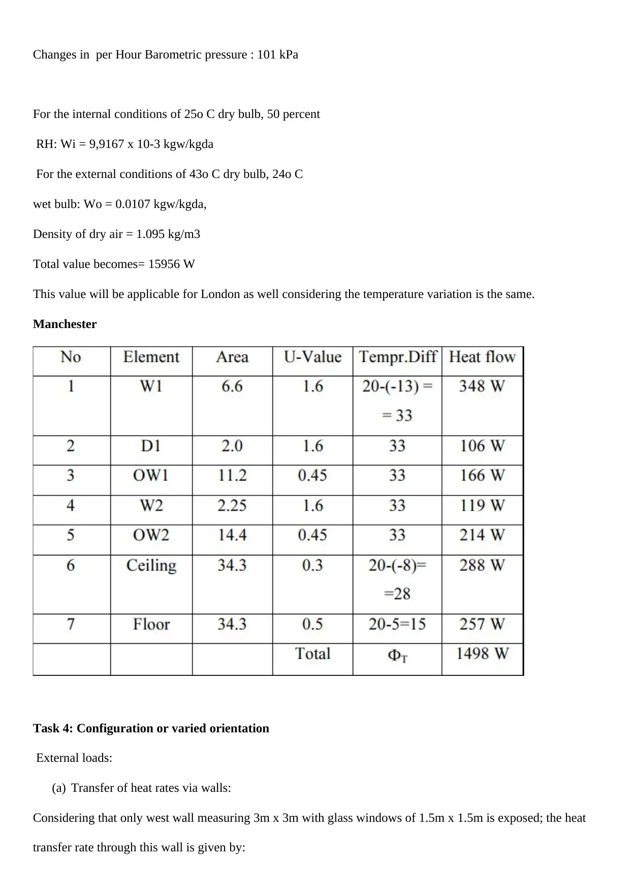
Changes in per Hour Barometric pressure : 101 kPa
For the internal conditions of 25o C dry bulb, 50 percent
RH: Wi = 9,9167 x 10⁻³ kgw/kgda
For the external conditions of 43o C dry bulb, 24o C
wet bulb: Wo = 0.0107 kgw/kgda,
Density of dry air = 1.095 kg/m3
Total value becomes= 15956 W
This value will be applicable for London as well considering the temperature variation is the same.
Manchester
Task 4: Configuration or varied orientation
External loads:
(a) Transfer of heat rates via walls:
Considering that only west wall measuring 3m x 3m with glass windows of 1.5m x 1.5m is exposed; the heat
transfer rate through this wall is given by:
Qwall = UwallAwallETDwall = 1.78 x (9-2.25) x 25 = 300.38 W.
b) Heat transfer rate through roof:
Qroof = UroofAroofETDroof = 1.316 x 18 x 30 = 710.6 W.
c) Heat rate transfer via the floor:
Considering that the building stands on a well-established, it can be assumed the conditions in the basement to
be same as that of the outside (i.e., 43o C dry bulb and 24o C wet bulb), since the floor is not exposed to solar
radiation, the driving temperature difference for the roof is the temperature difference between the outdoor and
indoor, hence: Qfloor = UfloorAfloorETDfloor = 1.2 x 18 x 18 = 388.8 W .
Task 5
(a) Heat transfer rate in the SW orientation:
This consists of the radiative as well as conductive components. Since no information is available on the value
of CLF, it is taken as 1.0. Hence the total heat transfer rate through the glass window is given by: Qglass =
Aglass [Uglass(To−Ti)+SHGFmaxSC] = 2.25[3.12 x 18 + 300 x 0.86] = 706.9 W (Sensible) e) Heat transfer
due to infiltration: The infiltration rate is 0.5 ACH, converting this into mass flow rate, the infiltration rate in
kg/s is given by: minf = density of air x (ACH x volume of the room)/3600 = 1.095 x (0.5 x 3x3x6)/3600 minf
= 8.2125 x 10⁻³ kg/s
Sensible heat transfer rate due to infiltration,Qs,inf; Qs,inf = minfcpm(To−Ti) = 8.2125 x 10-3 x 1021.6 x (43 –
25) = 151 W . Latent heat transfer rate due to infiltration, Ql,inf: Ql,inf = minfhfg(Wo−Wi) = 8.8125x10-3 x
2501x103 (0.0107−0.0099)=16.4 W.
b) Load due to SE orientation: The sensible and latent load due to occupants are: Qs,occ = no.of occupants x
SHG = 4 x 90 = 360 W Ql,occ = no.of occupants x LHG = 4 x 40 = 160 W b) Load due to lighting: Assuming a
CLF value of 1.0, the load due to lighting is: Qlights = 33 x floor area = 33 x 18 = 594 W (Sensible)
c) Load due NW orientation: Qs,app = 600 W (Sensible) Ql,app = 300 W (Latent)
Total sensible and latent loads are obtained by summing-up all the sensible and latent load components (both
external as well as internal) as: Qs,total = 300.38+710.6+388.8+706.9+151+360+594+600 = 3811.68 W
Ql,total = 16.4+160+300 = 476.4 W.
(d) Total load on the building is for NE orientation:
⊘ This is a preview!⊘
Do you want full access?
Subscribe today to unlock all pages.
Trusted by 1+ million students worldwide
Qtotal = Qs,total + Ql,total = 3811.68 + 476.4 = 4288.08 W Room Sensible Heat Factor (RSHF) is given by:
RSHF = Qs,total/Qtotal = 3811.68/4288.08 = 0.889. To calculate the required cooling capacity, one has to
know the losses in return air ducts(Sailor, Elley and Gibson 2012). Ventilation may be ignored as the
infiltration can take care of the small ventilation requirement. Hence using a safety factor of 1.25, the required
cooling capacity is: Required cooling capacity = 4288.08 x 1.25 = 5360.1 W ≈ 1.5 TR hence the best
orientation.
Task 6
Lightweight Vs Heavyweight Construction materials
In the summer seasons, there is need to control the heat gain effects even from the construction. This can be
achieved through integration of various types of the design of the structures and materials used. This however
depends on the predisposed factors that will finally impact the product(Hens 2017). The use of the products of
aluminum in the making of the roof instead of the timber will lead to the reduction of the weight of the
structure. Aluminium structures reflect much heat as compared to timber that absorbs heat and add weight as
well. When Expanded Polystyrene that is commonly known as EPS is used in the wall masonry instead of using
concrete for partitioning, the resultant structure will have light weight. The application of the EPS normally
requires the use of the shortcreting on both sides although this activity makes the material use very expensive.
Carbon fiber is generally another development material in the business however it turns out to be a treasure
waiting to be discovered and ideally time will uncover how powerful and adaptable it very well may be over
the long haul.
Corrugated iron sheets or Decra material tiles are additionally successful in accomplishing light weight
structure when contrasted with shingles and dirt material tiles.
They are additionally more savvy (moderately shabby upkeep cost) and tough. Suspension connect with
tensioned links is clearly lighter than a bracket connect with welded bars which thusly is lighter than a case
support connect made of cement(Pavlík, Žumár, Pavlíková and Černý 2012). Aluminum entryway and window
outlines are light load in contrast with steel outlines. The thing that matters isn't much yet at the same time
tallies. 3D printing (added substance producing) is another idea in the development business.
Paraphrase This Document
Need a fresh take? Get an instant paraphrase of this document with our AI Paraphraser
3D printing can utilize distinctive sorts of crude materials for printing of which a portion of this materials will
result in a light weight structures. Being generally new, the potential outcomes with 3D printing are relatively
boundless. This is a zone which needs concentrated and further research on. Bamboo can be utilized rather than
timber and still accomplish the ideal target and in the meantime bearing an a lot heavier load and it being a light
weight material.
Bamboo a be utilized rather than steel as support, however this should be looked into further since it might
require a thicker solid cover henceforth may increment of level up the dead load of the structure.
From the precedents above, there are a lot of materials one can use to accomplish plume weight structures
however for the majority of them to be in participated adequately into a building a great deal should be
considered. Cost being one of them. Workmanship (experienced) is likewise fundamental in the accomplishing
an ideal result which must be stylishly pleasing(Nelson, Hart, Zhou and Ozoliņš 2013). Durability is
additionally an essential point to be considered. Expectation that answers your inquiry. There are no
restrictions, not by any means the sky and there is just the same old thing new under the sun!
Task 7
Thermal comfort refers to the state of mind that actually expresses ones satisfaction with the thermal
environment. The thermal comfort is more than just known pleasant conditions. It should be considered part of
the survival behaviour. The following approaches can be used in the thermal comfort
Draught control
The vibe of draught relies upon air temperature, air development and air choppiness. The human body can't
detect the genuine air developments at low speed; however it can feel the expanded cooling of the skin, which
is caused by the air developments (Derluyn et al 2013). If not satisfactorily kept up VELUX rooftop windows
can be a wellspring of draught. More established rooftop windows with a harmed gasket can be defective and
given chilly air access to a room in winter. So visit upkeep is expected to keep the window in a decent
condition. Old and vast sheets may cause downdraught from the windows, where a chilly inside sheet
temperature cools the air and causes a descending air development. New low energy sheets are normally
preferred for the reduction of the draught effect.
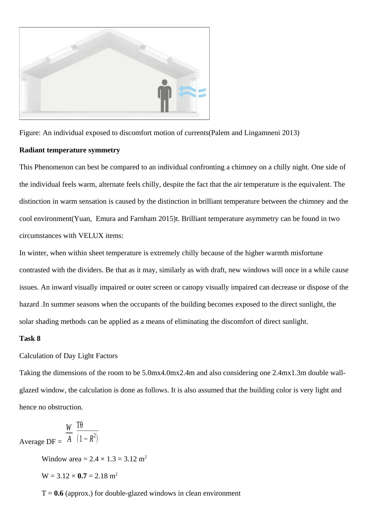
Figure: An individual exposed to discomfort motion of currents(Palem and Lingamneni 2013)
Radiant temperature symmetry
This Phenomenon can best be compared to an individual confronting a chimney on a chilly night. One side of
the individual feels warm, alternate feels chilly, despite the fact that the air temperature is the equivalent. The
distinction in warm sensation is caused by the distinction in brilliant temperature between the chimney and the
cool environment(Yuan, Emura and Farnham 2015)t. Brilliant temperature asymmetry can be found in two
circumstances with VELUX items:
In winter, when within sheet temperature is extremely chilly because of the higher warmth misfortune
contrasted with the dividers. Be that as it may, similarly as with draft, new windows will once in a while cause
issues. An inward visually impaired or outer screen or canopy visually impaired can decrease or dispose of the
hazard .In summer seasons when the occupants of the building becomes exposed to the direct sunlight, the
solar shading methods can be applied as a means of eliminating the discomfort of direct sunlight.
Task 8
Calculation of Day Light Factors
Taking the dimensions of the room to be 5.0mx4.0mx2.4m and also considering one 2.4mx1.3m double wall-
glazed window, the calculation is done as follows. It is also assumed that the building color is very light and
hence no obstruction.
Average DF =
W
A
Tθ
(1 − R2)
Window area = 2.4 × 1.3 = 3.12 m2
W = 3.12 × 0.7 = 2.18 m2
T = 0.6 (approx.) for double-glazed windows in clean environment
⊘ This is a preview!⊘
Do you want full access?
Subscribe today to unlock all pages.
Trusted by 1+ million students worldwide
1 out of 15
Related Documents


Your All-in-One AI-Powered Toolkit for Academic Success.
+13062052269
info@desklib.com
Available 24*7 on WhatsApp / Email
![[object Object]](/_next/static/media/star-bottom.7253800d.svg)
Unlock your academic potential
Copyright © 2020–2025 A2Z Services. All Rights Reserved. Developed and managed by ZUCOL.