Experimental Analysis of Heat Loss in Air Conditioning Ducts
VerifiedAdded on 2023/06/05
|20
|4159
|473
Practical Assignment
AI Summary
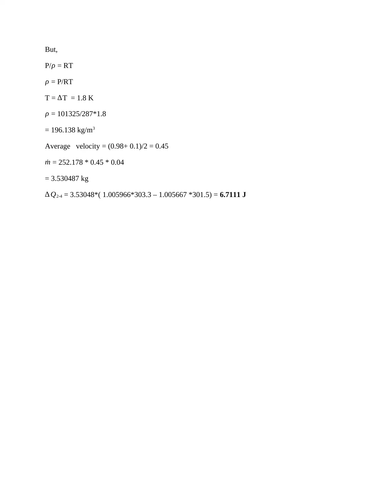
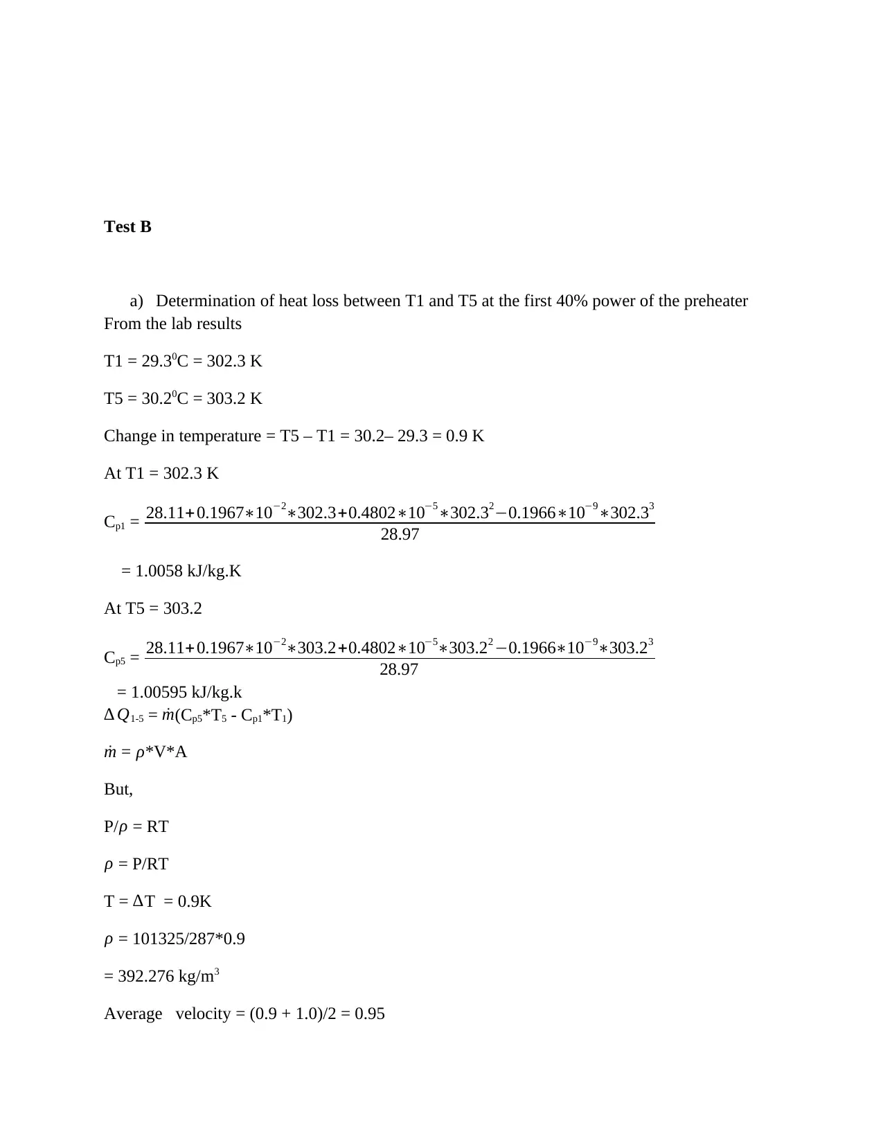
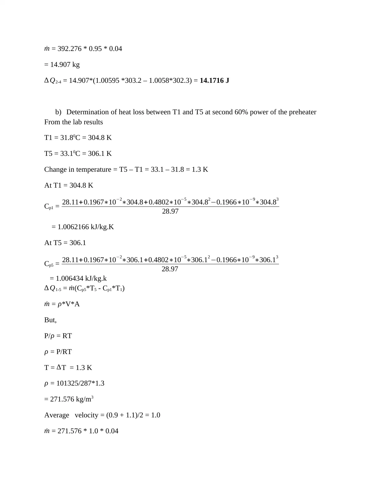
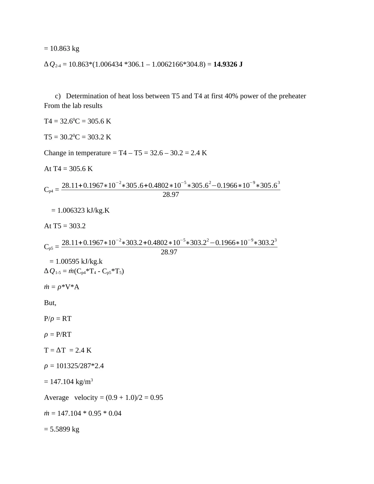
This practical assignment focuses on analyzing heat loss in air conditioning duct systems through experimental methods and calculations. The study determines heat loss between different temperature points (T2-T4 and T4-T5) in Test A, finding values of 7.4554 J and 6.7157 J for the first 40% and second 60% of the preheater's relative power, respectively. Test B showed higher heat loss due to greater temperature changes, with heat loss between T5-T1 and T4-T5 calculated as 14.1716 J and 14.9326 J for the first 40% and 14.133 J and 14.94733 J for the second 60% of the preheater's relative power, respectively. Additionally, the power dissipated by the preheater was calculated for both tests. The assignment also covers duct system performance criteria, fan laws, methodology, equipment, and procedures used in the experiment. Desklib offers a range of resources, including past papers and solved assignments, to support students in their studies.
1 out of 20
Related Documents


Your All-in-One AI-Powered Toolkit for Academic Success.
+13062052269
info@desklib.com
Available 24*7 on WhatsApp / Email
![[object Object]](/_next/static/media/star-bottom.7253800d.svg)
Copyright © 2020–2025 A2Z Services. All Rights Reserved. Developed and managed by ZUCOL.