Heat Loss and Power Dissipation in Air Conditioning Duct
VerifiedAdded on 2023/06/06
|19
|3847
|317
AI Summary
The study aims to determine heat flow rate and heat losses in air conditioning ducts, including the heat loss between T2 and T4 and T4 and T5 in test A, and the power supplied by preheater in test A and test B. The calculations show that an increase in temperature T2 results in an increase in heat loss. Heat loss in test B was found to be higher than in test A due to a higher change in temperature. The study also includes calculations for heat loss between T5 and T1 and T4 and T5 in test B.
Contribute Materials
Your contribution can guide someone’s learning journey. Share your
documents today.
Abstract
The calculations in test A for determining heat loss between temperature T2 and T4 together
with the calculation of the heat loss between temperature T4 and T5 where all determined and
found to be 7.4318 J and 7.4578 J and 7.444 J and 7.3773 J at the first 40% of the relative power
of preheater and the second 60% of the relative power of preheater of power of the heater.
The comparison was made between test A and B and was found out through calculation that heat
loss in test B were higher than those that were calculated in test A, because of a higher change in
temperature in test B.
Moreover, the calculation of heat loss in test B between temperature T5 and T1 and also
calculation of heat loss between temperature T4 and T5 were determined to be 14.16557 J and
14.919 J and 14.1762 J and 14.933 J at the first 40% of the relative power of preheater and the
second 60% of the relative power of preheater.
Furthermore, the calculation of power dissipated by the preheater was also determined in test A
between the temperature T1 and T2 as 7.443 W for the first 40% of the relative power of
preheater and 7.447 W for the second 60% of the relative power of preheater, similarly in test B
between the temperature T1 and T2 as 14.176 W for the first 40% of the relative power of
preheater and 14.931 W for the second 60% of the relative power of preheater.
Secure Best Marks with AI Grader
Need help grading? Try our AI Grader for instant feedback on your assignments.
Introduction
Operation of the air conditioning duct
Air conditioning comprises of several components that effectively helps it effective operations
that ranges from, recirculating duct, preheater and reheater, velocity meter, temperature sensors,
fans and louvres.
The process involves pumping air through ducts, with which its role is to keep the air inside the
system cool as it move through it, for energy efficiency of the air conditioning to be achieved the
system will be zoned, this will help the system to operate effectively at a constant sections that
will help the system not to be fully closed, in order to avoid building up pressure around the duct
that may cause damage.
Existence of regulators will help control the air that will enter through the diffuser into
circulation through the system zones, the diffusers role is to ensure that air is allowed to enter
through each and every required section, the regulators opens and close to ensure that fresh air
enters the system.
The system will receive back the air through grilles that helps to purify the air in circulation.
Objectives
1. To determine heat flow rate and heat losses
2. To determine the heat loss between T2 and T4 and the heat loss between T4 and T5 in
test A
3. To determine how heat loss is affected by temperature T2
4. To determine power supplied by preheater in test A and test B and discussing their there
difference.
5. To determine heat loss between T5 and T1, and heat loss between T4 and T5 in test B.
Results and Calculations
Equipment
Recirculating duct, preheater and reheater, velocity meter, a room model, five temperature
sensors (T1 to T5), sensors RH1 to RH5 and three louvres.
The following will be assumptions that will be used;
a) The air is assumed to be dry
b) The flow and temperature are taken to be uniform in the duct
c) The ideal gas law will be used to determine air density
d) The specific heat of air will be calculated based on the formula
Cp = 28.11+0.1967∗10−2∗T +0.4802∗10−5∗T 2−0.1966∗10−9∗T 3
28.97
Procedure
1. The air condenser absorbs the air into the ducts through the vents
2. The air is used to cool the gas in the evaporator, and in the process of removing heat
from the air it will be cooled,
3. The duct supplies the air back into the room.
4. Continuous supply cold air to the room until the air inside the room reaches a desired
temperature (Yau, 2008).
5. The thermostat sensor senses the temperature inside the room as reached a desired level
in order for it to automatically shut down the air conditioner
6. The process that will raise the temperature again in the room the thermostat is sense and
starts the air conditioner on again and the process
7. The process will continue again until, an ambient temperature will be achieved once
again (Yang, Yan, and Mullen, 2012).
8. Record the temperatures and velocities in the table below at 40% and 60% of relative
power of preheater
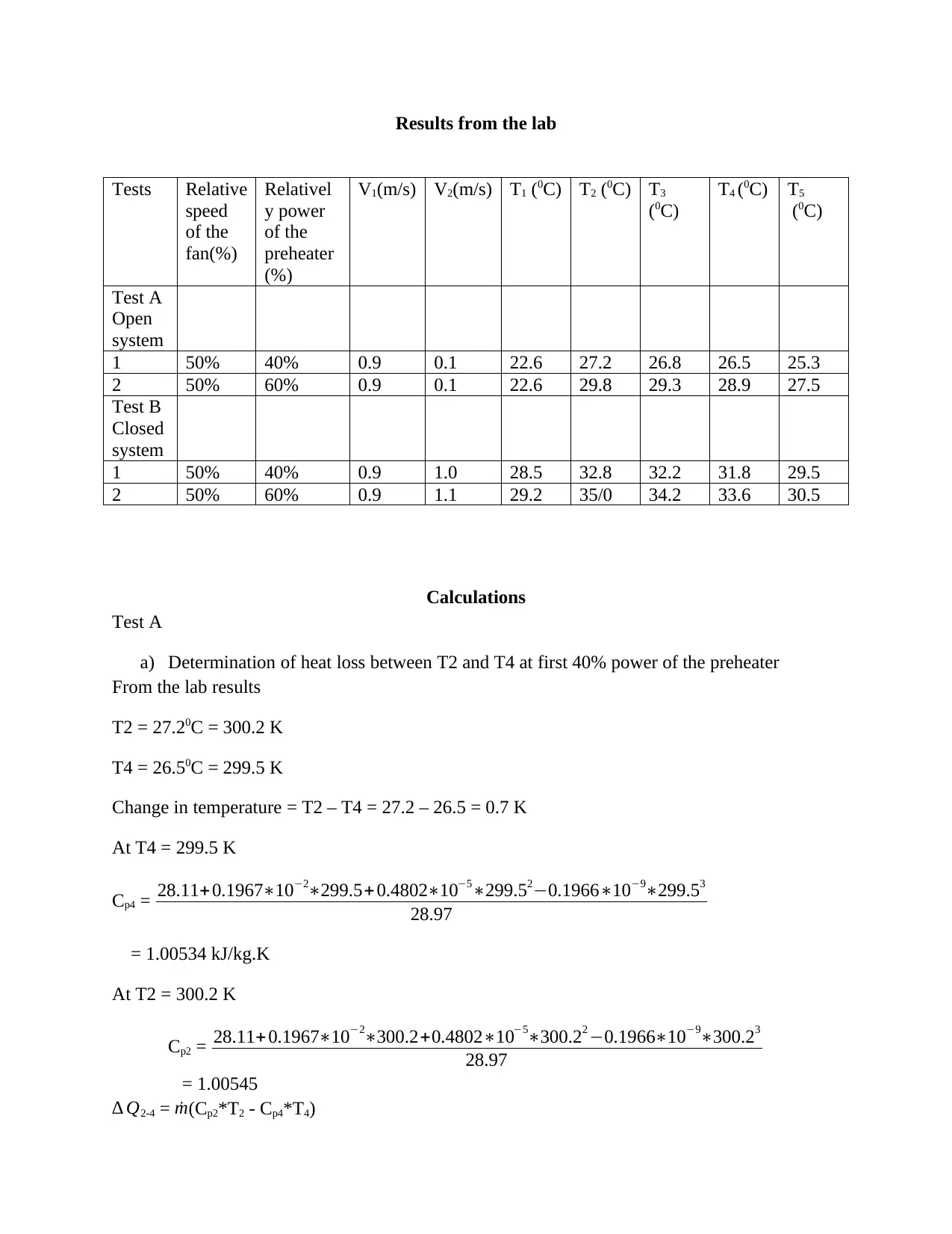
Results from the lab
Tests Relative
speed
of the
fan(%)
Relativel
y power
of the
preheater
(%)
V1(m/s) V2(m/s) T1 (0C) T2 (0C) T3
(0C)
T4 (0C) T5
(0C)
Test A
Open
system
1 50% 40% 0.9 0.1 22.6 27.2 26.8 26.5 25.3
2 50% 60% 0.9 0.1 22.6 29.8 29.3 28.9 27.5
Test B
Closed
system
1 50% 40% 0.9 1.0 28.5 32.8 32.2 31.8 29.5
2 50% 60% 0.9 1.1 29.2 35/0 34.2 33.6 30.5
Calculations
Test A
a) Determination of heat loss between T2 and T4 at first 40% power of the preheater
From the lab results
T2 = 27.20C = 300.2 K
T4 = 26.50C = 299.5 K
Change in temperature = T2 – T4 = 27.2 – 26.5 = 0.7 K
At T4 = 299.5 K
Cp4 = 28.11+0.1967∗10−2∗299.5+ 0.4802∗10−5∗299.52−0.1966∗10−9∗299.53
28.97
= 1.00534 kJ/kg.K
At T2 = 300.2 K
Cp2 = 28.11+ 0.1967∗10−2∗300.2+0.4802∗10−5∗300.22 −0.1966∗10−9∗300.23
28.97
= 1.00545
∆ Q2-4 = ˙m(Cp2*T2 - Cp4*T4)
Secure Best Marks with AI Grader
Need help grading? Try our AI Grader for instant feedback on your assignments.
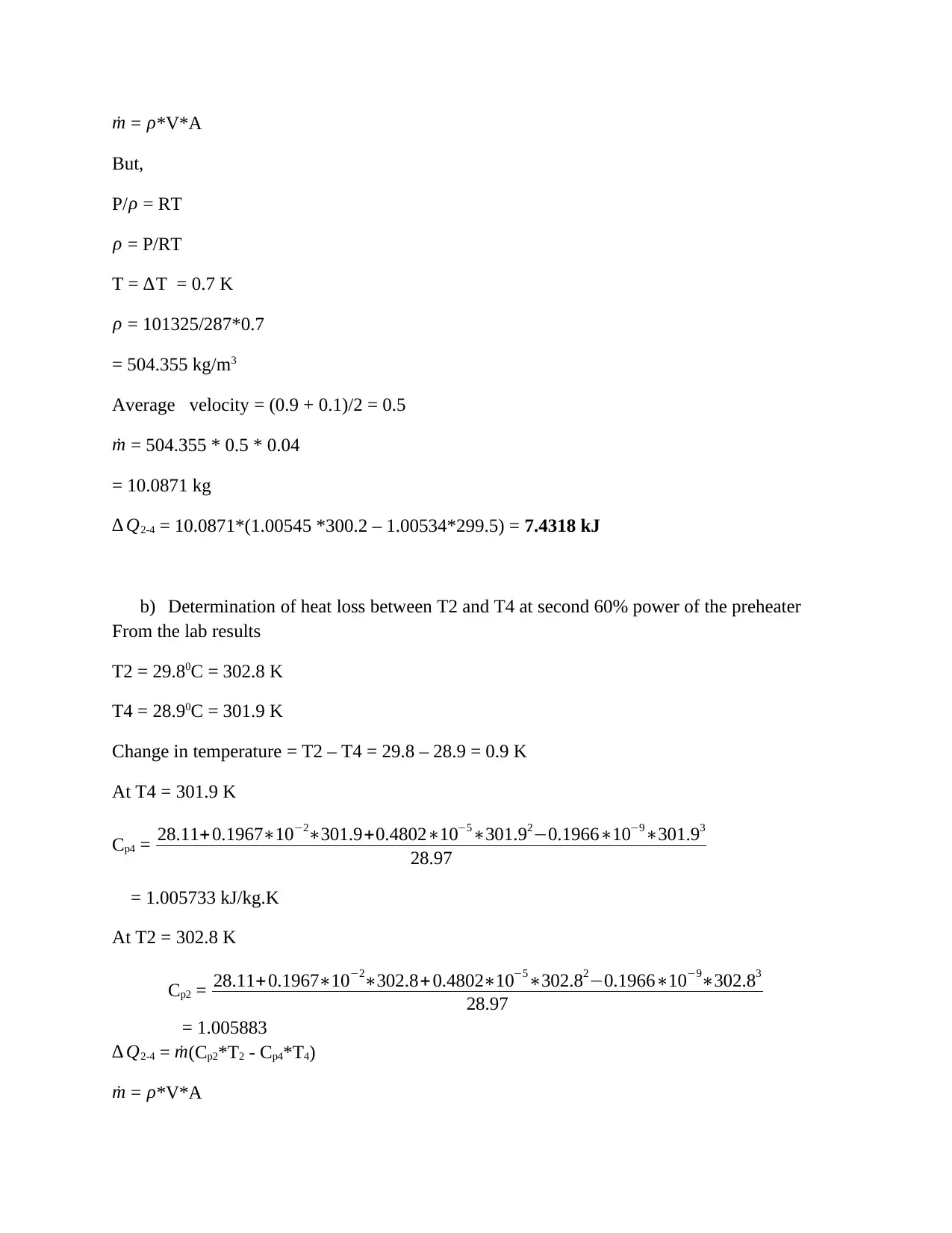
˙m = ρ*V*A
But,
P/ ρ = RT
ρ = P/RT
T = ∆T = 0.7 K
ρ = 101325/287*0.7
= 504.355 kg/m3
Average velocity = (0.9 + 0.1)/2 = 0.5
˙m = 504.355 * 0.5 * 0.04
= 10.0871 kg
∆ Q2-4 = 10.0871*(1.00545 *300.2 – 1.00534*299.5) = 7.4318 kJ
b) Determination of heat loss between T2 and T4 at second 60% power of the preheater
From the lab results
T2 = 29.80C = 302.8 K
T4 = 28.90C = 301.9 K
Change in temperature = T2 – T4 = 29.8 – 28.9 = 0.9 K
At T4 = 301.9 K
Cp4 = 28.11+0.1967∗10−2∗301.9+0.4802∗10−5∗301.92−0.1966∗10−9∗301.93
28.97
= 1.005733 kJ/kg.K
At T2 = 302.8 K
Cp2 = 28.11+0.1967∗10−2∗302.8+ 0.4802∗10−5∗302.82−0.1966∗10−9∗302.83
28.97
= 1.005883
∆ Q2-4 = ˙m(Cp2*T2 - Cp4*T4)
˙m = ρ*V*A
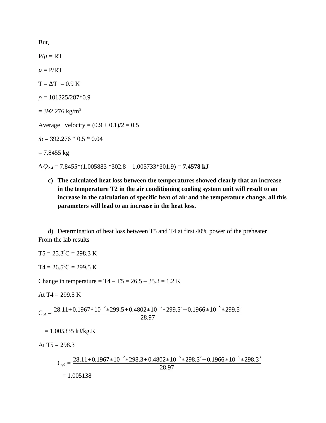
But,
P/ ρ = RT
ρ = P/RT
T = ∆T = 0.9 K
ρ = 101325/287*0.9
= 392.276 kg/m3
Average velocity = (0.9 + 0.1)/2 = 0.5
˙m = 392.276 * 0.5 * 0.04
= 7.8455 kg
∆ Q2-4 = 7.8455*(1.005883 *302.8 – 1.005733*301.9) = 7.4578 kJ
c) The calculated heat loss between the temperatures showed clearly that an increase
in the temperature T2 in the air conditioning cooling system unit will result to an
increase in the calculation of specific heat of air and the temperature change, all this
parameters will lead to an increase in the heat loss.
d) Determination of heat loss between T5 and T4 at first 40% power of the preheater
From the lab results
T5 = 25.30C = 298.3 K
T4 = 26.50C = 299.5 K
Change in temperature = T4 – T5 = 26.5 – 25.3 = 1.2 K
At T4 = 299.5 K
Cp4 = 28.11+0.1967∗10−2∗299.5+ 0.4802∗10−5∗299.52−0.1966∗10−9∗299.53
28.97
= 1.005335 kJ/kg.K
At T5 = 298.3
Cp5 = 28.11+0.1967∗10−2∗298.3+ 0.4802∗10−5∗298.32−0.1966∗10−9∗298.33
28.97
= 1.005138
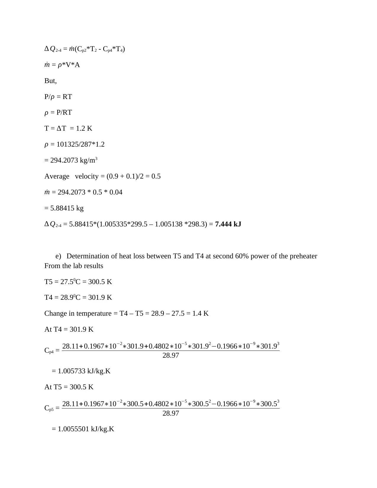
∆ Q2-4 = ˙m(Cp2*T2 - Cp4*T4)
˙m = ρ*V*A
But,
P/ ρ = RT
ρ = P/RT
T = ∆T = 1.2 K
ρ = 101325/287*1.2
= 294.2073 kg/m3
Average velocity = (0.9 + 0.1)/2 = 0.5
˙m = 294.2073 * 0.5 * 0.04
= 5.88415 kg
∆ Q2-4 = 5.88415*(1.005335*299.5 – 1.005138 *298.3) = 7.444 kJ
e) Determination of heat loss between T5 and T4 at second 60% power of the preheater
From the lab results
T5 = 27.50C = 300.5 K
T4 = 28.90C = 301.9 K
Change in temperature = T4 – T5 = 28.9 – 27.5 = 1.4 K
At T4 = 301.9 K
Cp4 = 28.11+0.1967∗10−2∗301.9+0.4802∗10−5∗301.92−0.1966∗10−9∗301.93
28.97
= 1.005733 kJ/kg.K
At T5 = 300.5 K
Cp5 = 28.11+0.1967∗10−2∗300.5+0.4802∗10−5∗300.52−0.1966∗10−9∗300.53
28.97
= 1.0055501 kJ/kg.K
Paraphrase This Document
Need a fresh take? Get an instant paraphrase of this document with our AI Paraphraser
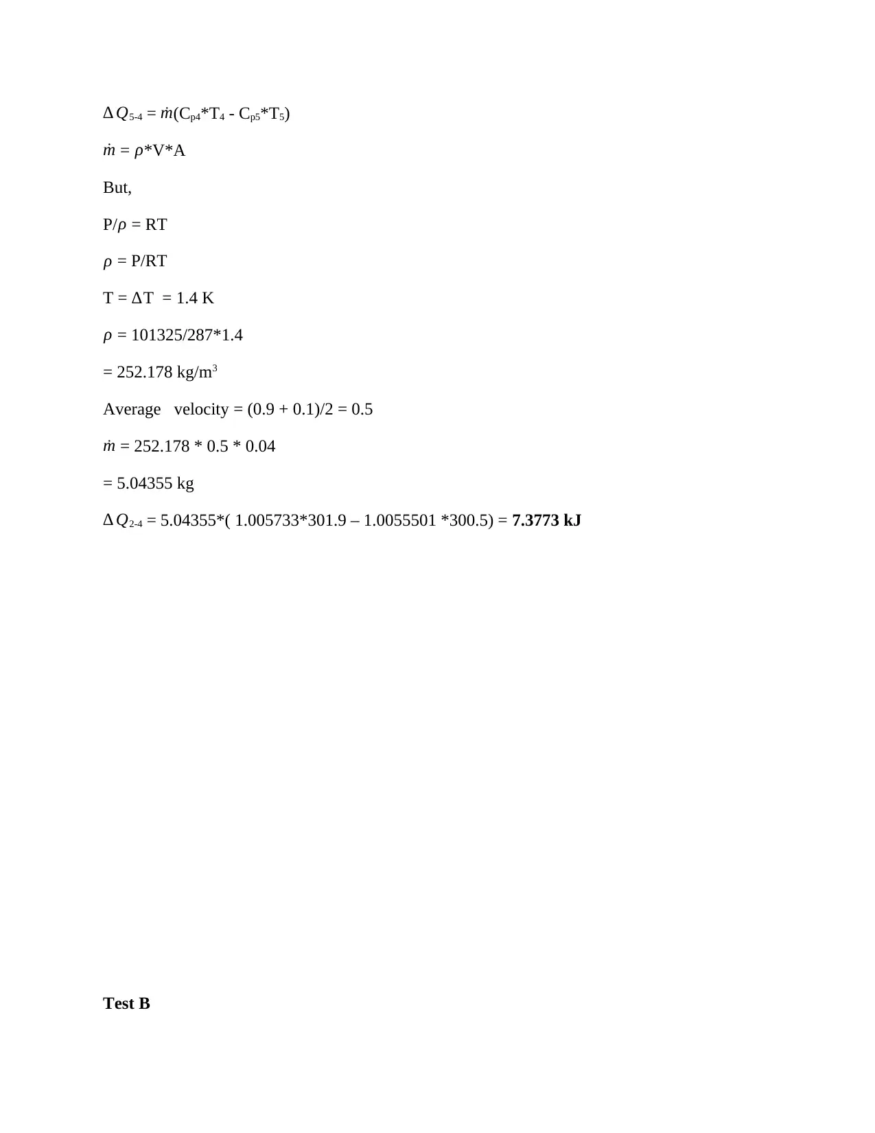
∆ Q5-4 = ˙m(Cp4*T4 - Cp5*T5)
˙m = ρ*V*A
But,
P/ ρ = RT
ρ = P/RT
T = ∆T = 1.4 K
ρ = 101325/287*1.4
= 252.178 kg/m3
Average velocity = (0.9 + 0.1)/2 = 0.5
˙m = 252.178 * 0.5 * 0.04
= 5.04355 kg
∆ Q2-4 = 5.04355*( 1.005733*301.9 – 1.0055501 *300.5) = 7.3773 kJ
Test B
˙m = ρ*V*A
But,
P/ ρ = RT
ρ = P/RT
T = ∆T = 1.4 K
ρ = 101325/287*1.4
= 252.178 kg/m3
Average velocity = (0.9 + 0.1)/2 = 0.5
˙m = 252.178 * 0.5 * 0.04
= 5.04355 kg
∆ Q2-4 = 5.04355*( 1.005733*301.9 – 1.0055501 *300.5) = 7.3773 kJ
Test B
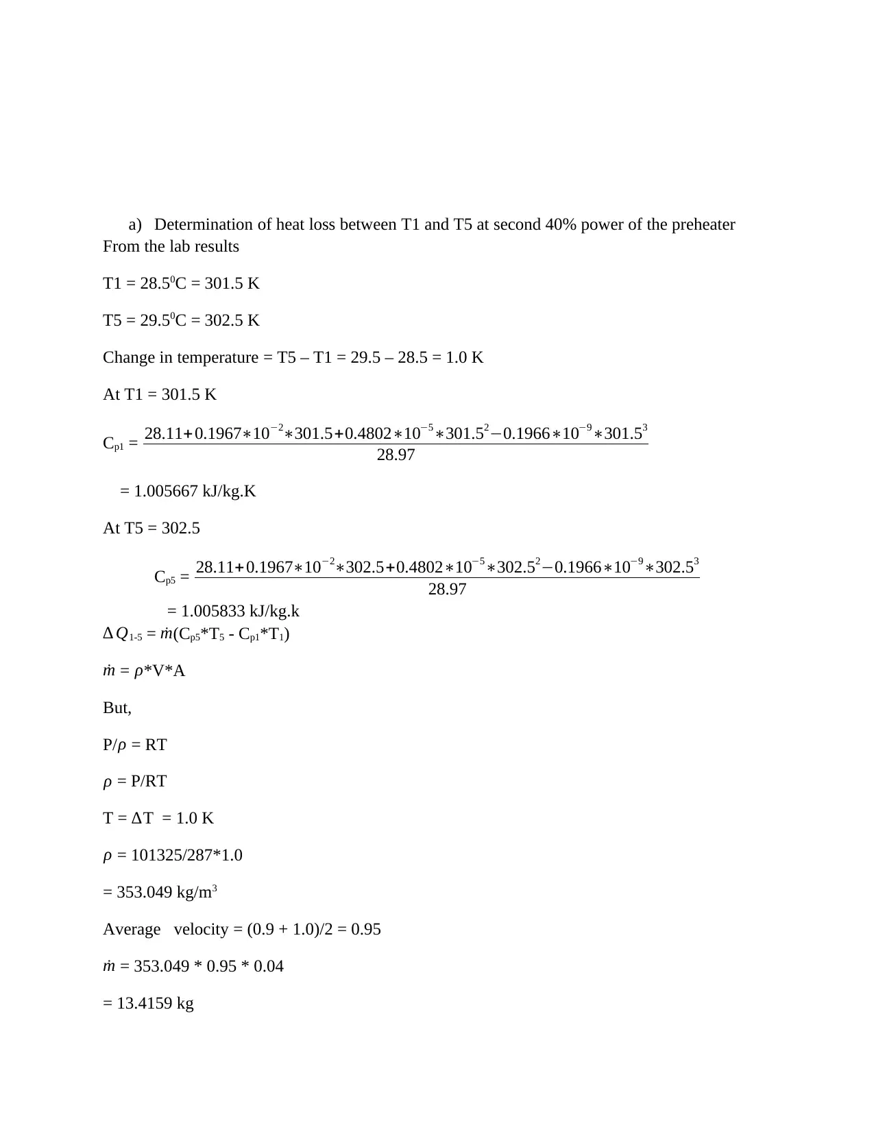
a) Determination of heat loss between T1 and T5 at second 40% power of the preheater
From the lab results
T1 = 28.50C = 301.5 K
T5 = 29.50C = 302.5 K
Change in temperature = T5 – T1 = 29.5 – 28.5 = 1.0 K
At T1 = 301.5 K
Cp1 = 28.11+0.1967∗10−2∗301.5+0.4802∗10−5∗301.52−0.1966∗10−9∗301.53
28.97
= 1.005667 kJ/kg.K
At T5 = 302.5
Cp5 = 28.11+0.1967∗10−2∗302.5+0.4802∗10−5∗302.52−0.1966∗10−9∗302.53
28.97
= 1.005833 kJ/kg.k
∆ Q1-5 = ˙m(Cp5*T5 - Cp1*T1)
˙m = ρ*V*A
But,
P/ ρ = RT
ρ = P/RT
T = ∆T = 1.0 K
ρ = 101325/287*1.0
= 353.049 kg/m3
Average velocity = (0.9 + 1.0)/2 = 0.95
˙m = 353.049 * 0.95 * 0.04
= 13.4159 kg
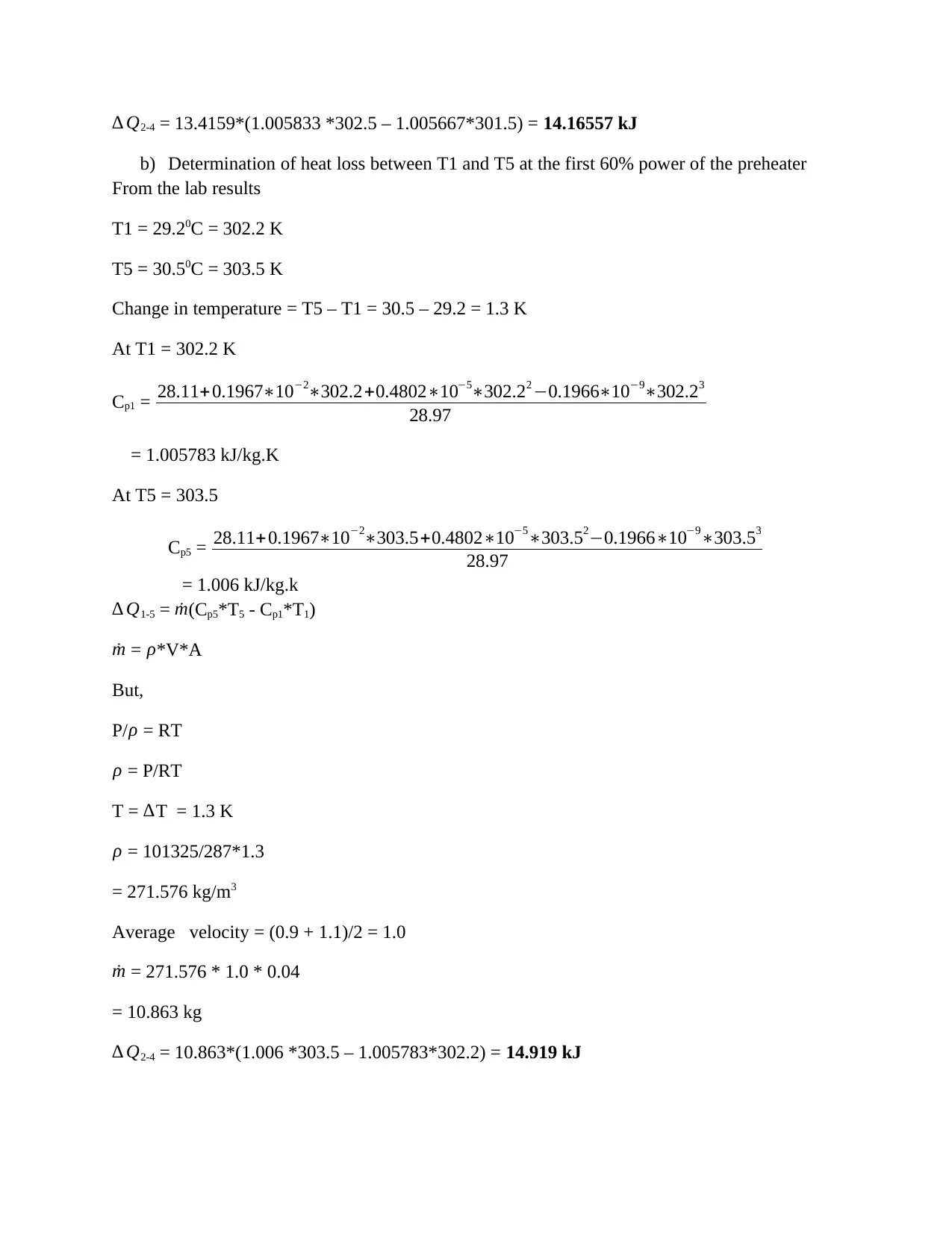
∆ Q2-4 = 13.4159*(1.005833 *302.5 – 1.005667*301.5) = 14.16557 kJ
b) Determination of heat loss between T1 and T5 at the first 60% power of the preheater
From the lab results
T1 = 29.20C = 302.2 K
T5 = 30.50C = 303.5 K
Change in temperature = T5 – T1 = 30.5 – 29.2 = 1.3 K
At T1 = 302.2 K
Cp1 = 28.11+ 0.1967∗10−2∗302.2+0.4802∗10−5∗302.22 −0.1966∗10−9∗302.23
28.97
= 1.005783 kJ/kg.K
At T5 = 303.5
Cp5 = 28.11+0.1967∗10−2∗303.5+0.4802∗10−5∗303.52−0.1966∗10−9∗303.53
28.97
= 1.006 kJ/kg.k
∆ Q1-5 = ˙m(Cp5*T5 - Cp1*T1)
˙m = ρ*V*A
But,
P/ρ = RT
ρ = P/RT
T = ∆T = 1.3 K
ρ = 101325/287*1.3
= 271.576 kg/m3
Average velocity = (0.9 + 1.1)/2 = 1.0
˙m = 271.576 * 1.0 * 0.04
= 10.863 kg
∆ Q2-4 = 10.863*(1.006 *303.5 – 1.005783*302.2) = 14.919 kJ
Secure Best Marks with AI Grader
Need help grading? Try our AI Grader for instant feedback on your assignments.
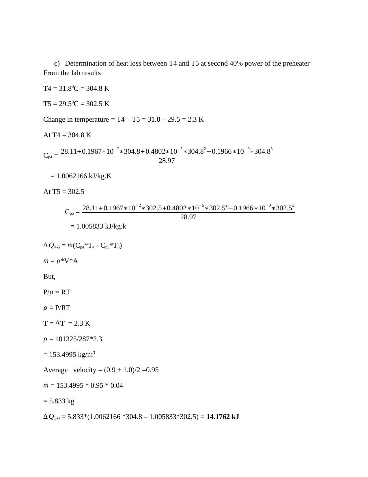
c) Determination of heat loss between T4 and T5 at second 40% power of the preheater
From the lab results
T4 = 31.80C = 304.8 K
T5 = 29.50C = 302.5 K
Change in temperature = T4 – T5 = 31.8 – 29.5 = 2.3 K
At T4 = 304.8 K
Cp4 = 28.11+0.1967∗10−2∗304.8+ 0.4802∗10−5∗304.82−0.1966∗10−9∗304.83
28.97
= 1.0062166 kJ/kg.K
At T5 = 302.5
Cp5 = 28.11+0.1967∗10−2∗302.5+0.4802∗10−5∗302.52−0.1966∗10−9∗302.53
28.97
= 1.005833 kJ/kg.k
∆ Q4-5 = ˙m(Cp4*T4 - Cp5*T5)
˙m = ρ*V*A
But,
P/ρ = RT
ρ = P/RT
T = ∆T = 2.3 K
ρ = 101325/287*2.3
= 153.4995 kg/m3
Average velocity = (0.9 + 1.0)/2 =0.95
˙m = 153.4995 * 0.95 * 0.04
= 5.833 kg
∆ Q5-4 = 5.833*(1.0062166 *304.8 – 1.005833*302.5) = 14.1762 kJ
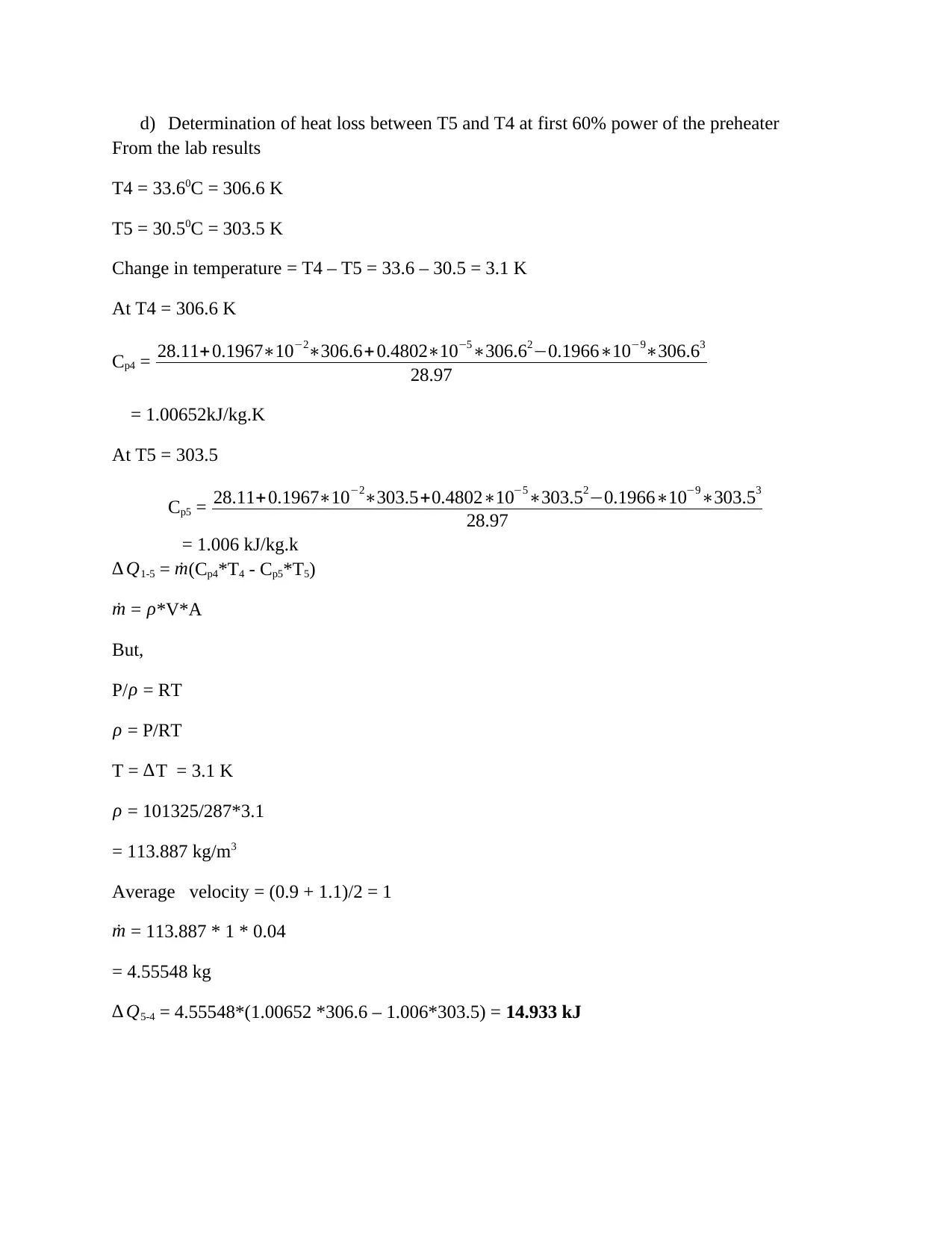
d) Determination of heat loss between T5 and T4 at first 60% power of the preheater
From the lab results
T4 = 33.60C = 306.6 K
T5 = 30.50C = 303.5 K
Change in temperature = T4 – T5 = 33.6 – 30.5 = 3.1 K
At T4 = 306.6 K
Cp4 = 28.11+0.1967∗10−2∗306.6+ 0.4802∗10−5∗306.62−0.1966∗10−9∗306.63
28.97
= 1.00652kJ/kg.K
At T5 = 303.5
Cp5 = 28.11+0.1967∗10−2∗303.5+0.4802∗10−5∗303.52−0.1966∗10−9∗303.53
28.97
= 1.006 kJ/kg.k
∆ Q1-5 = ˙m(Cp4*T4 - Cp5*T5)
˙m = ρ*V*A
But,
P/ρ = RT
ρ = P/RT
T = ∆T = 3.1 K
ρ = 101325/287*3.1
= 113.887 kg/m3
Average velocity = (0.9 + 1.1)/2 = 1
˙m = 113.887 * 1 * 0.04
= 4.55548 kg
∆ Q5-4 = 4.55548*(1.00652 *306.6 – 1.006*303.5) = 14.933 kJ
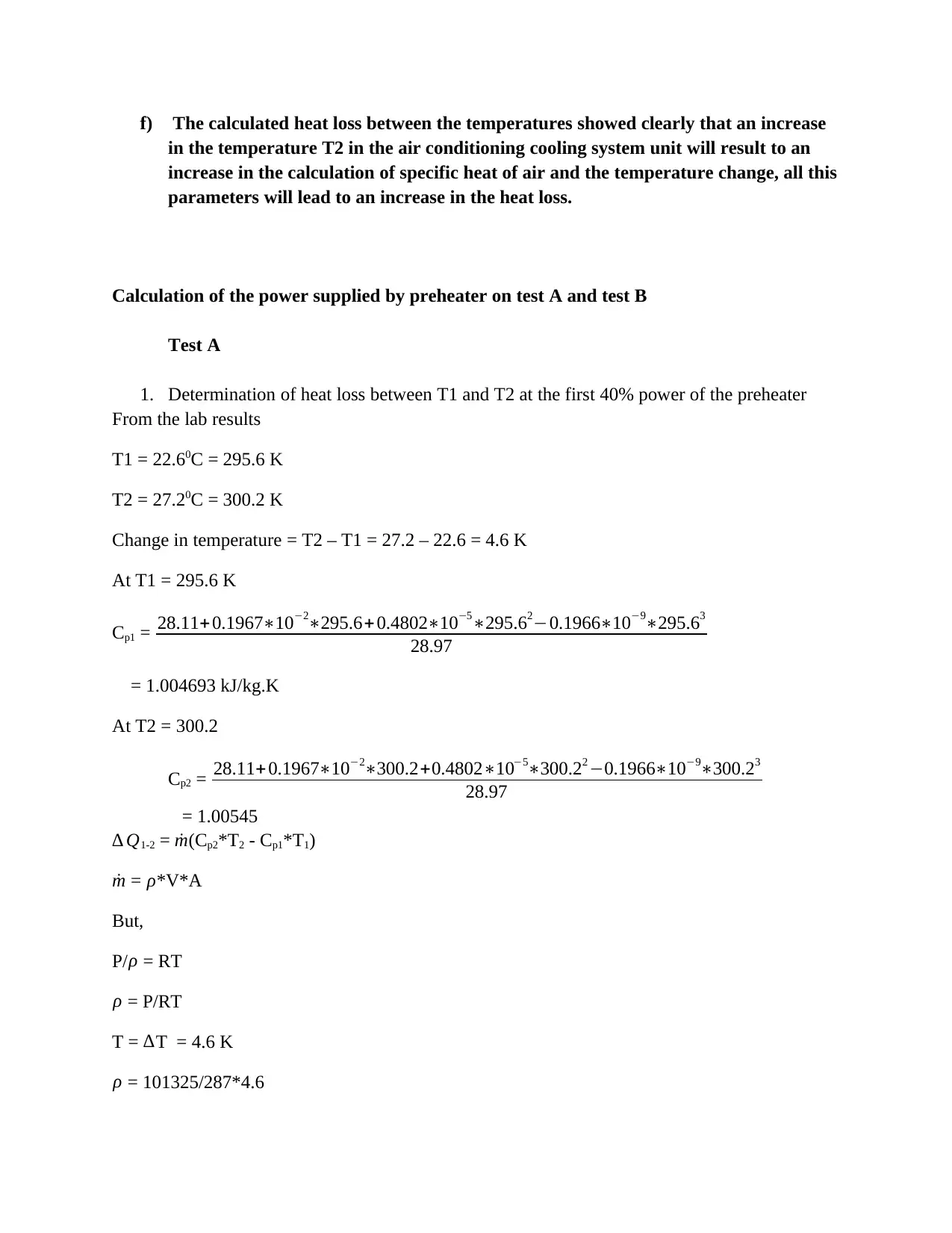
f) The calculated heat loss between the temperatures showed clearly that an increase
in the temperature T2 in the air conditioning cooling system unit will result to an
increase in the calculation of specific heat of air and the temperature change, all this
parameters will lead to an increase in the heat loss.
Calculation of the power supplied by preheater on test A and test B
Test A
1. Determination of heat loss between T1 and T2 at the first 40% power of the preheater
From the lab results
T1 = 22.60C = 295.6 K
T2 = 27.20C = 300.2 K
Change in temperature = T2 – T1 = 27.2 – 22.6 = 4.6 K
At T1 = 295.6 K
Cp1 = 28.11+0.1967∗10−2∗295.6+ 0.4802∗10−5∗295.62−0.1966∗10−9∗295.63
28.97
= 1.004693 kJ/kg.K
At T2 = 300.2
Cp2 = 28.11+ 0.1967∗10−2∗300.2+0.4802∗10−5∗300.22 −0.1966∗10−9∗300.23
28.97
= 1.00545
∆ Q1-2 = ˙m(Cp2*T2 - Cp1*T1)
˙m = ρ*V*A
But,
P/ ρ = RT
ρ = P/RT
T = ∆T = 4.6 K
ρ = 101325/287*4.6
Paraphrase This Document
Need a fresh take? Get an instant paraphrase of this document with our AI Paraphraser
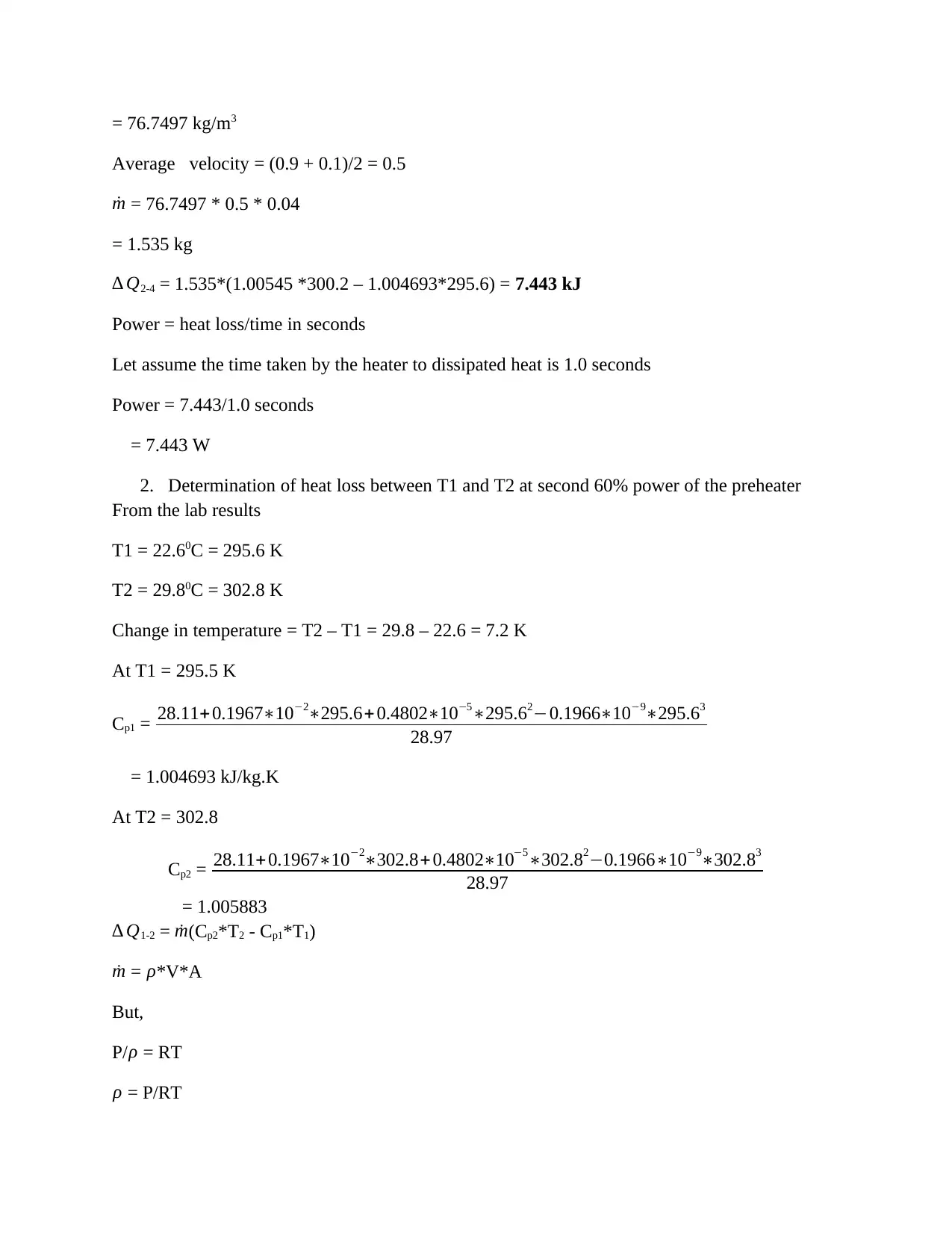
= 76.7497 kg/m3
Average velocity = (0.9 + 0.1)/2 = 0.5
˙m = 76.7497 * 0.5 * 0.04
= 1.535 kg
∆ Q2-4 = 1.535*(1.00545 *300.2 – 1.004693*295.6) = 7.443 kJ
Power = heat loss/time in seconds
Let assume the time taken by the heater to dissipated heat is 1.0 seconds
Power = 7.443/1.0 seconds
= 7.443 W
2. Determination of heat loss between T1 and T2 at second 60% power of the preheater
From the lab results
T1 = 22.60C = 295.6 K
T2 = 29.80C = 302.8 K
Change in temperature = T2 – T1 = 29.8 – 22.6 = 7.2 K
At T1 = 295.5 K
Cp1 = 28.11+0.1967∗10−2∗295.6+ 0.4802∗10−5∗295.62−0.1966∗10−9∗295.63
28.97
= 1.004693 kJ/kg.K
At T2 = 302.8
Cp2 = 28.11+0.1967∗10−2∗302.8+ 0.4802∗10−5∗302.82−0.1966∗10−9∗302.83
28.97
= 1.005883
∆ Q1-2 = ˙m(Cp2*T2 - Cp1*T1)
˙m = ρ*V*A
But,
P/ ρ = RT
ρ = P/RT
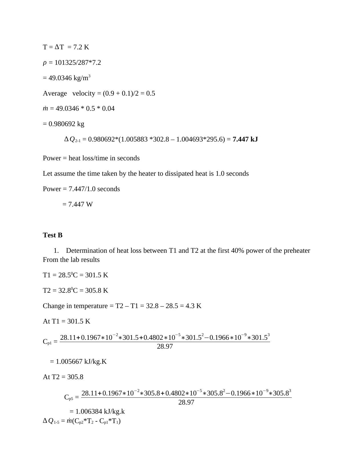
T = ∆T = 7.2 K
ρ = 101325/287*7.2
= 49.0346 kg/m3
Average velocity = (0.9 + 0.1)/2 = 0.5
˙m = 49.0346 * 0.5 * 0.04
= 0.980692 kg
∆ Q2-1 = 0.980692*(1.005883 *302.8 – 1.004693*295.6) = 7.447 kJ
Power = heat loss/time in seconds
Let assume the time taken by the heater to dissipated heat is 1.0 seconds
Power = 7.447/1.0 seconds
= 7.447 W
Test B
1. Determination of heat loss between T1 and T2 at the first 40% power of the preheater
From the lab results
T1 = 28.50C = 301.5 K
T2 = 32.80C = 305.8 K
Change in temperature = T2 – T1 = 32.8 – 28.5 = 4.3 K
At T1 = 301.5 K
Cp1 = 28.11+0.1967∗10−2∗301.5+0.4802∗10−5∗301.52−0.1966∗10−9∗301.53
28.97
= 1.005667 kJ/kg.K
At T2 = 305.8
Cp5 = 28.11+0.1967∗10−2∗305.8+ 0.4802∗10−5∗305.82−0.1966∗10−9∗305.83
28.97
= 1.006384 kJ/kg.k
∆ Q1-5 = ˙m(Cp2*T2 - Cp1*T1)
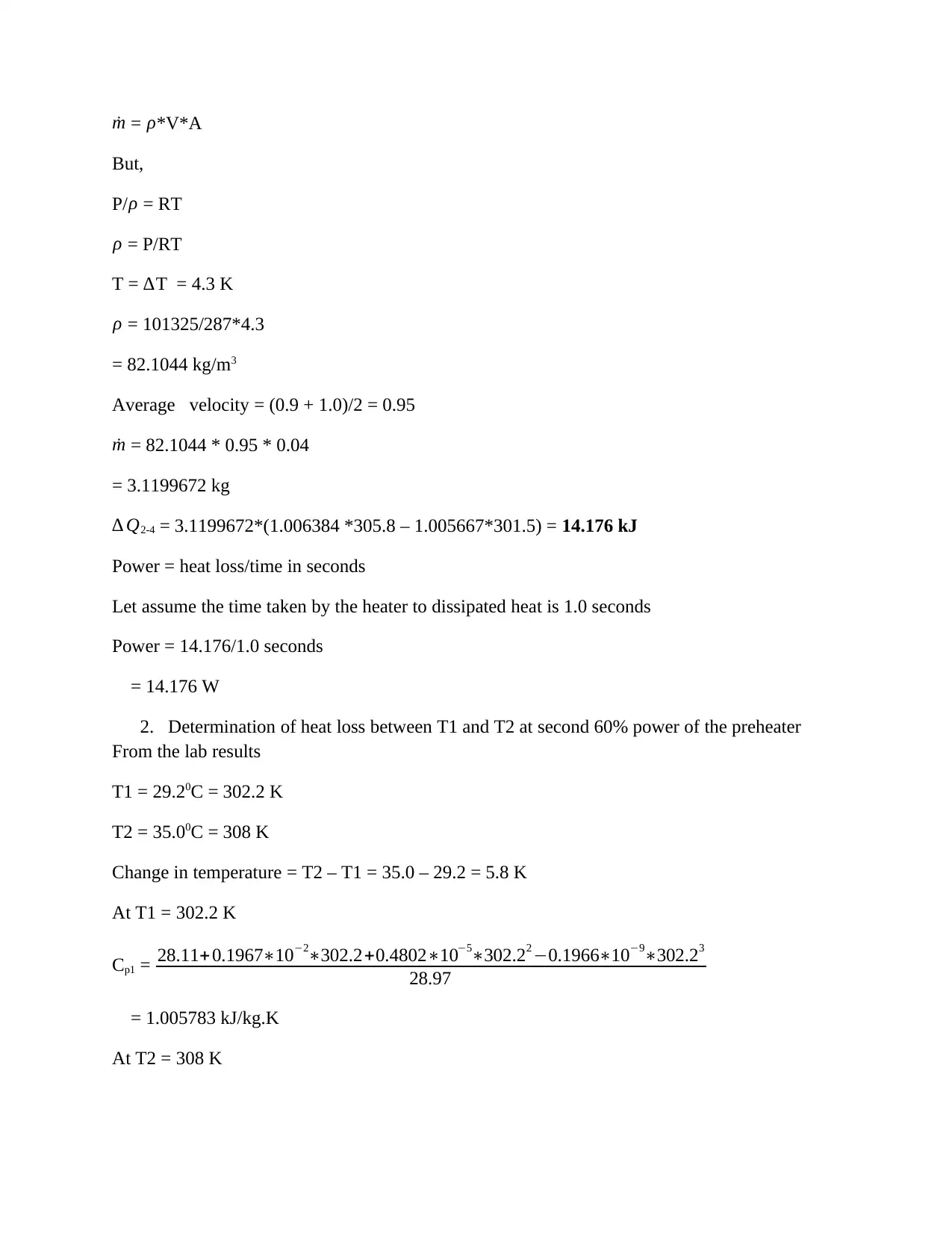
˙m = ρ*V*A
But,
P/ ρ = RT
ρ = P/RT
T = ∆T = 4.3 K
ρ = 101325/287*4.3
= 82.1044 kg/m3
Average velocity = (0.9 + 1.0)/2 = 0.95
˙m = 82.1044 * 0.95 * 0.04
= 3.1199672 kg
∆ Q2-4 = 3.1199672*(1.006384 *305.8 – 1.005667*301.5) = 14.176 kJ
Power = heat loss/time in seconds
Let assume the time taken by the heater to dissipated heat is 1.0 seconds
Power = 14.176/1.0 seconds
= 14.176 W
2. Determination of heat loss between T1 and T2 at second 60% power of the preheater
From the lab results
T1 = 29.20C = 302.2 K
T2 = 35.00C = 308 K
Change in temperature = T2 – T1 = 35.0 – 29.2 = 5.8 K
At T1 = 302.2 K
Cp1 = 28.11+ 0.1967∗10−2∗302.2+0.4802∗10−5∗302.22 −0.1966∗10−9∗302.23
28.97
= 1.005783 kJ/kg.K
At T2 = 308 K
Secure Best Marks with AI Grader
Need help grading? Try our AI Grader for instant feedback on your assignments.
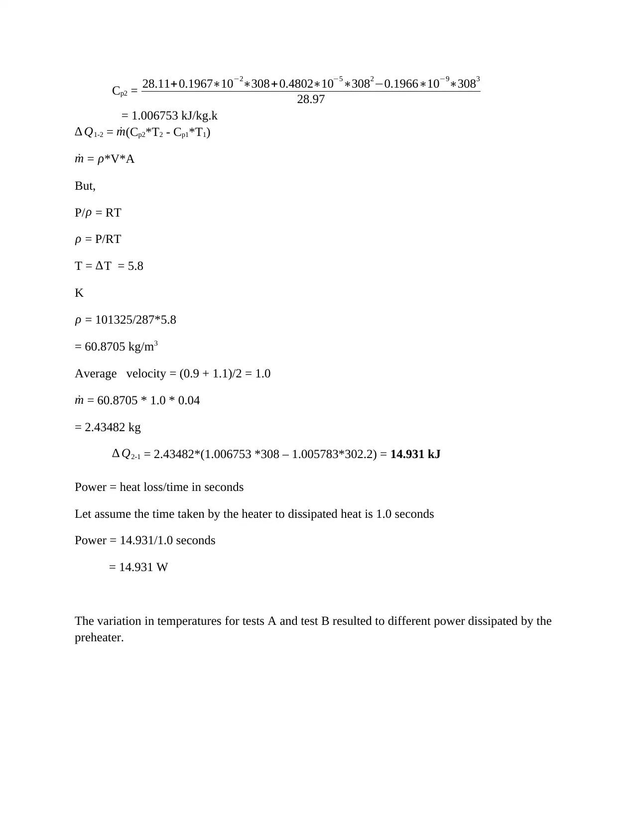
Cp2 = 28.11+0.1967∗10−2∗308+0.4802∗10−5∗3082−0.1966∗10−9∗3083
28.97
= 1.006753 kJ/kg.k
∆ Q1-2 = ˙m(Cp2*T2 - Cp1*T1)
˙m = ρ*V*A
But,
P/ ρ = RT
ρ = P/RT
T = ∆T = 5.8
K
ρ = 101325/287*5.8
= 60.8705 kg/m3
Average velocity = (0.9 + 1.1)/2 = 1.0
˙m = 60.8705 * 1.0 * 0.04
= 2.43482 kg
∆ Q2-1 = 2.43482*(1.006753 *308 – 1.005783*302.2) = 14.931 kJ
Power = heat loss/time in seconds
Let assume the time taken by the heater to dissipated heat is 1.0 seconds
Power = 14.931/1.0 seconds
= 14.931 W
The variation in temperatures for tests A and test B resulted to different power dissipated by the
preheater.
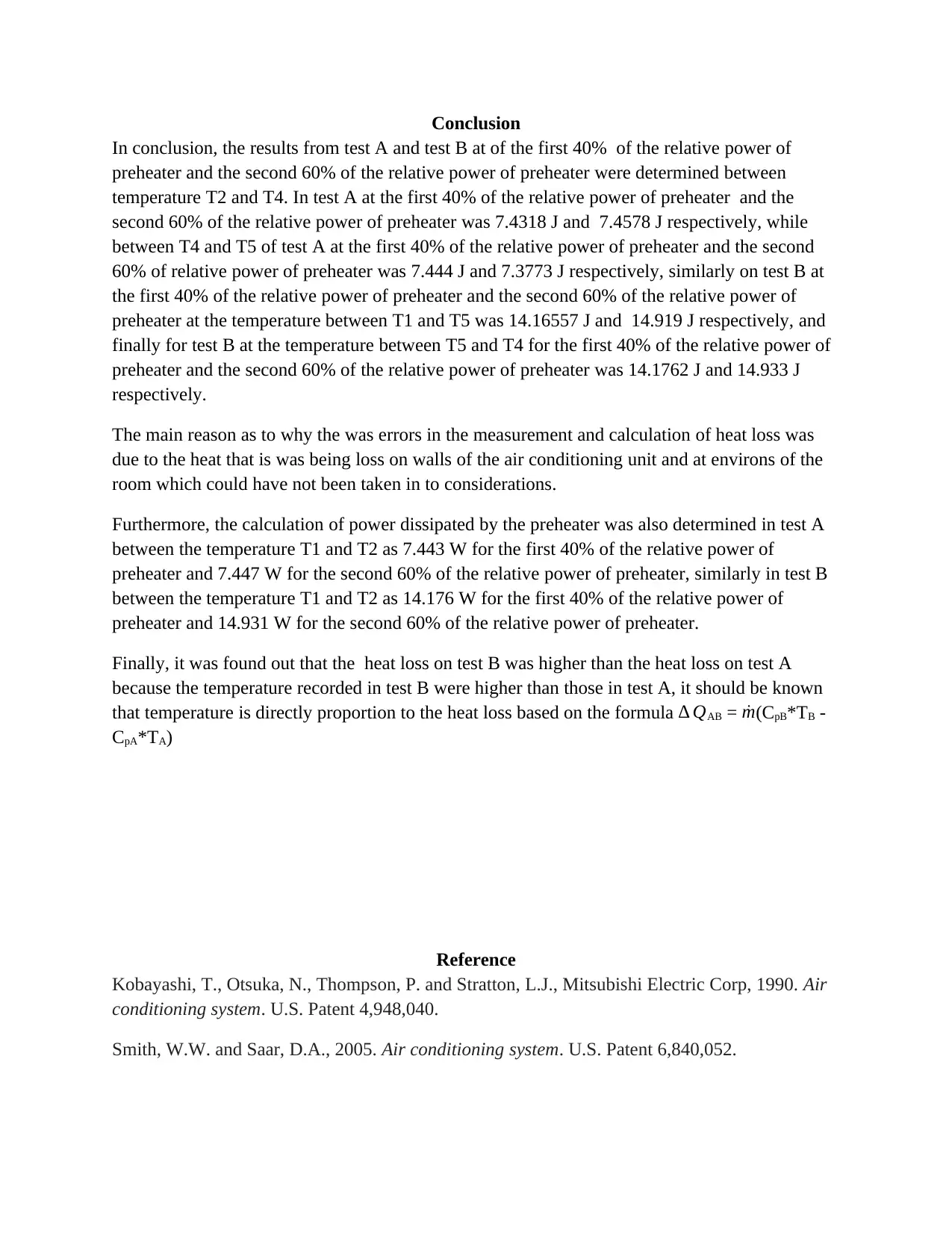
Conclusion
In conclusion, the results from test A and test B at of the first 40% of the relative power of
preheater and the second 60% of the relative power of preheater were determined between
temperature T2 and T4. In test A at the first 40% of the relative power of preheater and the
second 60% of the relative power of preheater was 7.4318 J and 7.4578 J respectively, while
between T4 and T5 of test A at the first 40% of the relative power of preheater and the second
60% of relative power of preheater was 7.444 J and 7.3773 J respectively, similarly on test B at
the first 40% of the relative power of preheater and the second 60% of the relative power of
preheater at the temperature between T1 and T5 was 14.16557 J and 14.919 J respectively, and
finally for test B at the temperature between T5 and T4 for the first 40% of the relative power of
preheater and the second 60% of the relative power of preheater was 14.1762 J and 14.933 J
respectively.
The main reason as to why the was errors in the measurement and calculation of heat loss was
due to the heat that is was being loss on walls of the air conditioning unit and at environs of the
room which could have not been taken in to considerations.
Furthermore, the calculation of power dissipated by the preheater was also determined in test A
between the temperature T1 and T2 as 7.443 W for the first 40% of the relative power of
preheater and 7.447 W for the second 60% of the relative power of preheater, similarly in test B
between the temperature T1 and T2 as 14.176 W for the first 40% of the relative power of
preheater and 14.931 W for the second 60% of the relative power of preheater.
Finally, it was found out that the heat loss on test B was higher than the heat loss on test A
because the temperature recorded in test B were higher than those in test A, it should be known
that temperature is directly proportion to the heat loss based on the formula ∆ QAB = ˙m(CpB*TB -
CpA*TA)
Reference
Kobayashi, T., Otsuka, N., Thompson, P. and Stratton, L.J., Mitsubishi Electric Corp, 1990. Air
conditioning system. U.S. Patent 4,948,040.
Smith, W.W. and Saar, D.A., 2005. Air conditioning system. U.S. Patent 6,840,052.
Funakoshi, S., Matsuo, K., Nakamura, H., Matsushima, H., Hisajima, D., Nishiguchi, A.,
Yamamoto, T., Umeda, T. and Hashimoto, K., Hitachi Ltd, 1992. Air conditioning system. U.S.
Patent 5,156,203.
Mcgrath, W.L., Carrier Corp, 1972. Air conditioning system. U.S. Patent 3,653,589.
Mcfarlan, A.I., MCFARLAN ALDEN I, 1957. Air conditioning system. U.S. Patent 2,797,068.
Hiden, E. and Salmio, E., Flakt Woods AB, 2004. Air-conditioning duct system. U.S. Patent
Application 10/257,250
1 out of 19
Related Documents


Your All-in-One AI-Powered Toolkit for Academic Success.
+13062052269
info@desklib.com
Available 24*7 on WhatsApp / Email
![[object Object]](/_next/static/media/star-bottom.7253800d.svg)
Unlock your academic potential
© 2024 | Zucol Services PVT LTD | All rights reserved.