HEV Engine Optimization: Performance, Configuration, and Modeling
VerifiedAdded on 2022/08/18
|31
|5267
|17
Project
AI Summary
This project delves into the optimization of Hybrid Electric Vehicle (HEV) engines, addressing the critical balance between high performance, emissions, and fuel efficiency. The research investigates the relationship between energy recuperation and driving cycles within HEVs, focusing on the integration of electric vehicles into simulated programs and the proposition of methods to enhance overall vehicle performance. It covers detailed engine component analysis, including electric motors and batteries, and discusses key issues such as energy management and HEV control. The paper also explores engine modeling processes, including mathematical modeling and the analysis of different driving modes and their impact on performance validation. By reconfiguring combustion components and introducing a multi-piston combustion chamber, the project aims to optimize engine configurations for improved efficiency and reduced emissions. The project utilizes an optimization design framework to identify the most suitable strategies for battery recharge energy recuperation in hybrid electric cars, with the ultimate goal of enhancing fuel economy and reducing emissions. The study emphasizes the importance of component configuration and the use of algorithms to reduce costs and limitations associated with prototype development. The project highlights the potential of HEVs to mitigate environmental pollution through efficient engine configurations.

HEV Engine Optimization 1
School Name
Name of class
Professor
School Location
Date
School Name
Name of class
Professor
School Location
Date
Paraphrase This Document
Need a fresh take? Get an instant paraphrase of this document with our AI Paraphraser
HEV Engine Optimization 2
Executive summary
Environmentally friendly cars having a wide range of performance abilities exceeding ordinary
and conventional vehicles need a careful and well-maintained balance among the most
competing objectives that will ensure high performance, emissions, and fuel efficiency. The
energy of deceleration can be recuperated for the vehicle to utilize it in battery recharge in the
energy storage hybrid electric vehicle (HEV) and boost the overall state of the batteries
depending on the new prevailing conditions of the braking phase of the vehicle. HEVs have
inbuilt power storage unit, which is used in reducing the needed peak power value from the
prime mover of the car, which forms part of the engine’s internal combustion chamber. This
paper investigates the existing relationship between recuperating energy and the driving cycle
stages of the Hybrid Electric vehicles to the inbuilt battery system of these cars. This works will
also offer various ways to integrate this electric vehicle into a simulated program. Different
methods of improving the overall performance of the vehicle will be posited. An optimization
design framework is used in the research paper to identify the most suitable position that can be
adopted to recuperate the energy of battery recharge in hybrid electric cars.
HEV Engine Optimization 3
Contents
Executive summary.........................................................................................................................2
Introduction......................................................................................................................................5
Problem statement.......................................................................................................................6
Objectives....................................................................................................................................8
Conceptual engine diagram.............................................................................................................8
Configuration description of an HEV..............................................................................................9
Detailed engine components analysis........................................................................................11
Electric motor........................................................................................................................11
Batteries.................................................................................................................................13
Main issues................................................................................................................................14
HEV Control..........................................................................................................................15
HEV energy management......................................................................................................19
Transmission..........................................................................................................................20
Assembled Drawing.......................................................................................................................21
HEV engine optimization..............................................................................................................21
Overview....................................................................................................................................21
Engine modeling process...........................................................................................................22
Mathematical modeling.........................................................................................................22
⊘ This is a preview!⊘
Do you want full access?
Subscribe today to unlock all pages.

Trusted by 1+ million students worldwide
HEV Engine Optimization 4
Engine mathematical modeling.............................................................................................23
Gera shift process and working modes of the optimized powertrain....................................23
Engine working modes..............................................................................................................24
Electric Vehicle driving mode...............................................................................................24
HEV overpowered and underpowered driving modes...........................................................25
Performance validation..............................................................................................................27
Conclusion.....................................................................................................................................27
Future studies.............................................................................................................................28
References......................................................................................................................................29
Paraphrase This Document
Need a fresh take? Get an instant paraphrase of this document with our AI Paraphraser
HEV Engine Optimization 5
Introduction
Engine emission in automobiles is considered a significant factor in the discharge of
concentrated pollution in the world, especially in cities. However, the internal combustion engine
has remained the most preferred and the dominant automobile mover for technological adoption
and overall cost of production reasons (Zhang and Sheng 2016). Further, the ever-growing
dependency on fossil oil among the increasing concern regarding its overall environmental
impact of personal means of transportation has led to a global need by the governments to initiate
and sponsor various research into the creation of alternative vehicles to save on the overall
amount of the energy consumed, (Jeong, Kim, Lim, Park, Cha, and Jang, 2017). One of the new
automobiles is the creation of hybrid electric vehicles, typically including both the electric motor
and an internal combustion engine, with the primary objective of producing low emissions while
establishing a superior fuel economy around the globe.
As for engine improvement and optimization, numerous actions need to be taken, which include
optimization of the structure of the engine and the use of highly sophisticated engine control
approaches. Currently, HEV technology uses the Atkinson cycle as a mode of energy transfer in
the engine to obtain useful work. The Atkinson sequence is a tool of compensation for the engine
weakness observed in the Atkinson engine with the aid of the motor. Apart from the utilization
of the Atkinson cycle, other systems and technologies, which include the use of cold Exhaust
Gas Recirculation (EGR) and the installation of an optimized cylinder structure, are highly useful
in enhancing engine efficiency. Most of these technologies have been explored by companies
like Honda, Toyota, Hyundai, and Chevrolet.
HEV Engine Optimization 6
In addition to the use of spark ignition, the use of low-temperature combustion has shown signs
of improving the general motor fuel economic performance especially targeting hybrid vehicles,
where electrocution of the powertrain of the engine can give extra amounts of energy units to
propel the car and decouple the driver making the engine to function effectively and efficiently.
Great exploration has been conducted on the LTC engine in different perspectives. In a more
homogeneous charge compression ignition, the cell arrangement was put in a series form, and
three different energy management control was employed to gauge its influence on the fuel
consumption of the car.
In the modern technology-driven engineering modification world, an electro-mechanical
compound hybrid transmission offers an optimum mechanism to improve engine optimization
and maximize the overall performance of the vehicle. In relation to the traits of fast response,
pollution-free and increased adoption of LTC engine, the engine motor is highly suitable to serve
as an alternative source of power to the vehicle. Commonly, HEVs can be subdivided into three
different categories according to the cell’s arrangement in its electric engine compartment;
parallel configuration, series configuration, and series-parallel configuration.
Problem statement
HEV is an automobile having at least two propulsion means. One of these sources is the electric
energy. Most of the common designs in the market today include; electric motor, power control,
and a peaking device that comes in combination with the power units that include: sterling
engine/fuel cell, diesel engine, or spark ignition, (Kim, Kim and Kum 2015). Once the desired
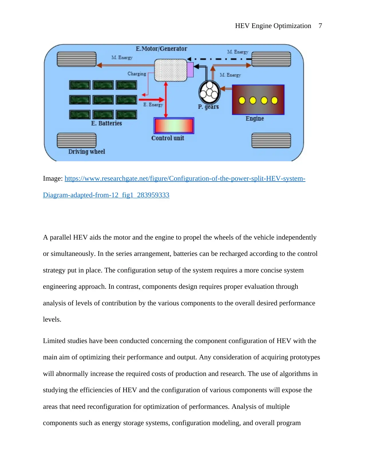
components have been picked, they can be setup in several configurations. The components
arrangements can be put in the form of parallel and series
⊘ This is a preview!⊘
Do you want full access?
Subscribe today to unlock all pages.

Trusted by 1+ million students worldwide
HEV Engine Optimization 7
Image: https://www.researchgate.net/figure/Configuration-of-the-power-split-HEV-system-
Diagram-adapted-from-12_fig1_283959333
A parallel HEV aids the motor and the engine to propel the wheels of the vehicle independently
or simultaneously. In the series arrangement, batteries can be recharged according to the control
strategy put in place. The configuration setup of the system requires a more concise system
engineering approach. In contrast, components design requires proper evaluation through
analysis of levels of contribution by the various components to the overall desired performance
levels.
Limited studies have been conducted concerning the component configuration of HEV with the
main aim of optimizing their performance and output. Any consideration of acquiring prototypes
will abnormally increase the required costs of production and research. The use of algorithms in
studying the efficiencies of HEV and the configuration of various components will expose the
areas that need reconfiguration for optimization of performances. Analysis of multiple
components such as energy storage systems, configuration modeling, and overall program
Paraphrase This Document
Need a fresh take? Get an instant paraphrase of this document with our AI Paraphraser
HEV Engine Optimization 8
simulation will require high costs to acquire their prototypes (Pei, Su and Zhang 2017).
Therefore, the adoption of the use of algorithms will help to decrease the total costs with reduced
limitations on carrying repeated research exercise. The purpose of the algorithm is preferred over
the use of expensive prototypes. It can be used to carry out simulations and identify the areas that
require reconfiguration to optimize the overall performance of the HEV.
Environmental pollution has attracted global attention, and the manufacturing of HEV offers a
solution to this menace. With the current efforts put in place to tackle the danger, it is essential to
adopt efficient and highly reliable HEVs to help in the reduction of strong emissions. Therefore,
it is crucial to upgrade the current engine configuration that will ensure performance
optimization.
Objectives
1. Understand the overall analysis of the hybrid engine
2. To reconfigure the arrangements of combustion components by modifying the engine
with the introduction of a multi-piston combustion chamber
3. Justify the findings and conclusion
Conceptual engine diagram
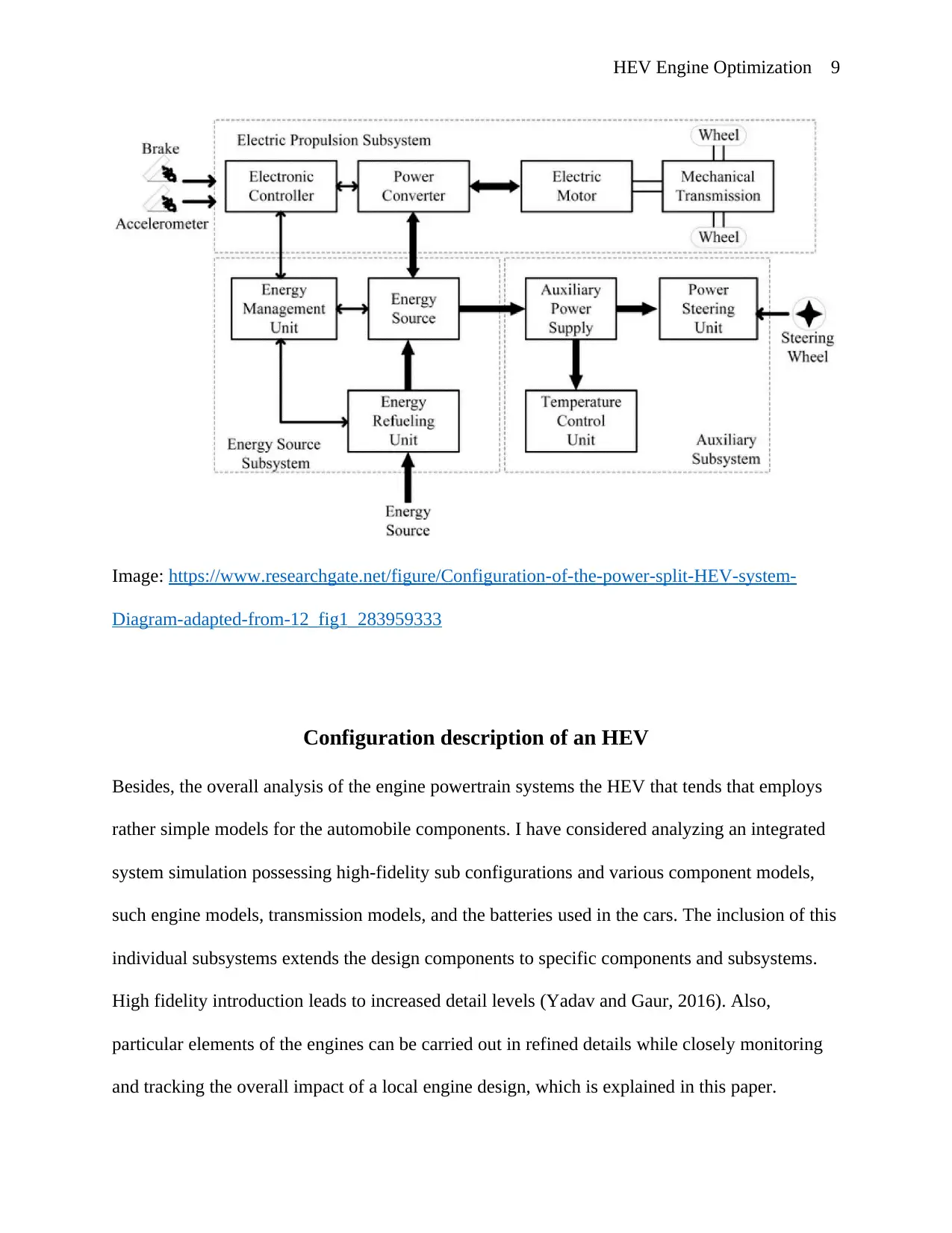
Energy and fuel combustion are initiated by the driver through the acceleration piston and during
the deceleration periods while driving. A contemporary image of the HEVs engine is illustrated
in the picture below, showing the flow of command that initiates the acceleration and
deceleration hence calling for energy combustion.
HEV Engine Optimization 9
Image: https://www.researchgate.net/figure/Configuration-of-the-power-split-HEV-system-
Diagram-adapted-from-12_fig1_283959333
Configuration description of an HEV
Besides, the overall analysis of the engine powertrain systems the HEV that tends that employs
rather simple models for the automobile components. I have considered analyzing an integrated
system simulation possessing high-fidelity sub configurations and various component models,
such engine models, transmission models, and the batteries used in the cars. The inclusion of this
individual subsystems extends the design components to specific components and subsystems.
High fidelity introduction leads to increased detail levels (Yadav and Gaur, 2016). Also,
particular elements of the engines can be carried out in refined details while closely monitoring
and tracking the overall impact of a local engine design, which is explained in this paper.
⊘ This is a preview!⊘
Do you want full access?
Subscribe today to unlock all pages.

Trusted by 1+ million students worldwide
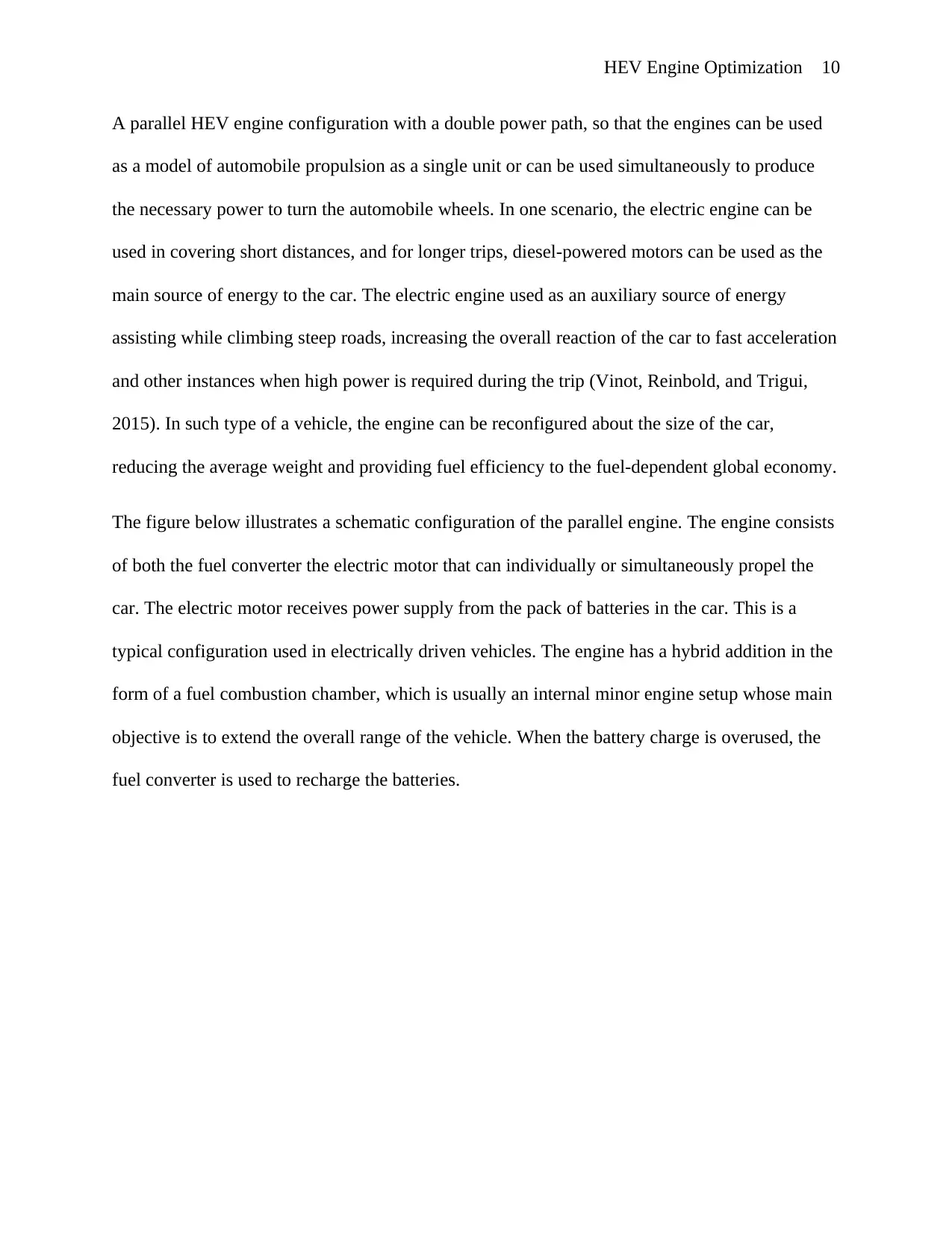
HEV Engine Optimization 10
A parallel HEV engine configuration with a double power path, so that the engines can be used
as a model of automobile propulsion as a single unit or can be used simultaneously to produce
the necessary power to turn the automobile wheels. In one scenario, the electric engine can be
used in covering short distances, and for longer trips, diesel-powered motors can be used as the
main source of energy to the car. The electric engine used as an auxiliary source of energy
assisting while climbing steep roads, increasing the overall reaction of the car to fast acceleration
and other instances when high power is required during the trip (Vinot, Reinbold, and Trigui,
2015). In such type of a vehicle, the engine can be reconfigured about the size of the car,
reducing the average weight and providing fuel efficiency to the fuel-dependent global economy.
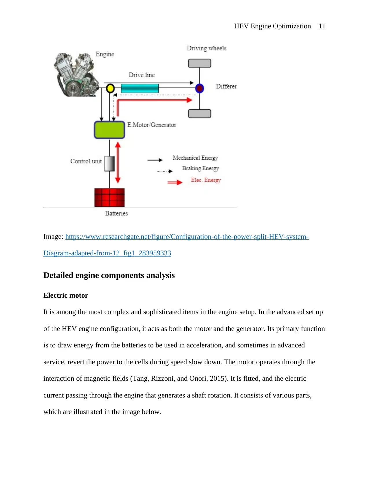
The figure below illustrates a schematic configuration of the parallel engine. The engine consists
of both the fuel converter the electric motor that can individually or simultaneously propel the
car. The electric motor receives power supply from the pack of batteries in the car. This is a
typical configuration used in electrically driven vehicles. The engine has a hybrid addition in the
form of a fuel combustion chamber, which is usually an internal minor engine setup whose main
objective is to extend the overall range of the vehicle. When the battery charge is overused, the
fuel converter is used to recharge the batteries.
Paraphrase This Document
Need a fresh take? Get an instant paraphrase of this document with our AI Paraphraser
HEV Engine Optimization 11
Image: https://www.researchgate.net/figure/Configuration-of-the-power-split-HEV-system-
Diagram-adapted-from-12_fig1_283959333
Detailed engine components analysis
Electric motor
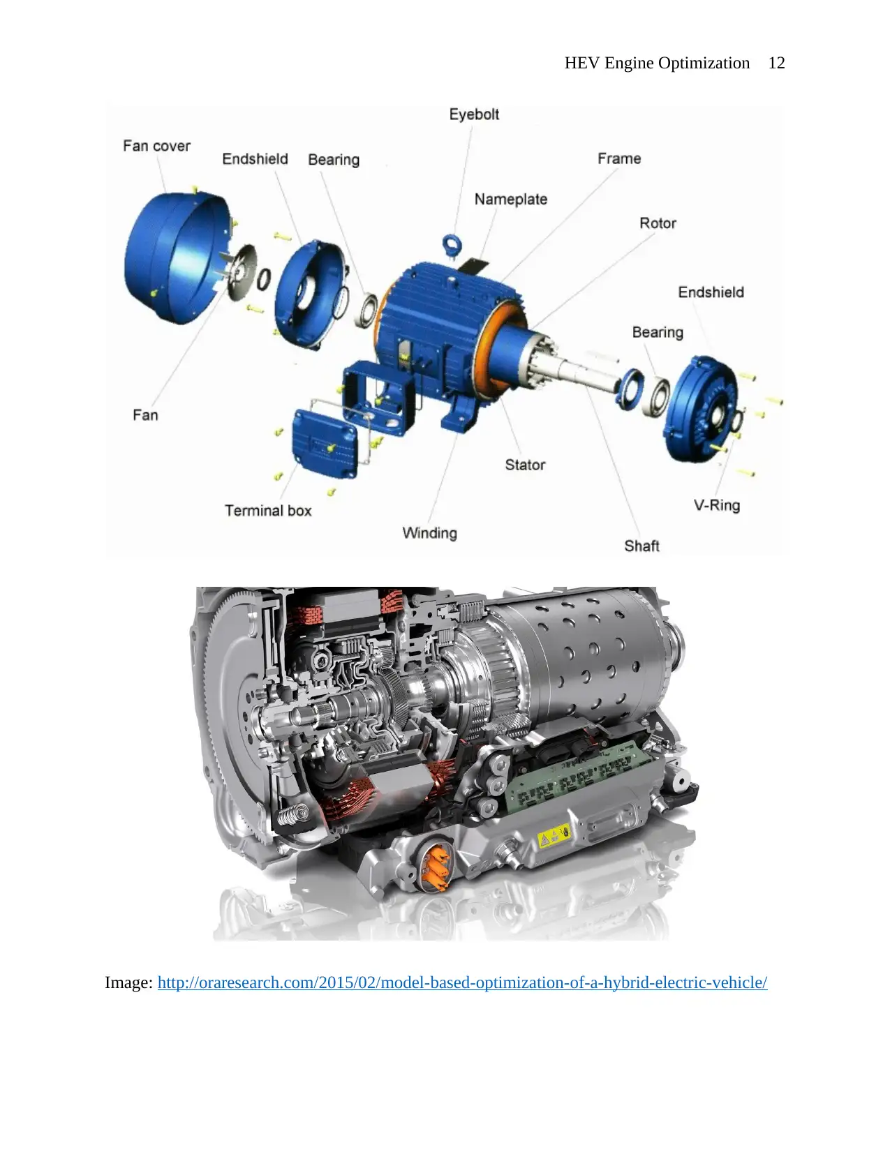
It is among the most complex and sophisticated items in the engine setup. In the advanced set up
of the HEV engine configuration, it acts as both the motor and the generator. Its primary function
is to draw energy from the batteries to be used in acceleration, and sometimes in advanced
service, revert the power to the cells during speed slow down. The motor operates through the
interaction of magnetic fields (Tang, Rizzoni, and Onori, 2015). It is fitted, and the electric
current passing through the engine that generates a shaft rotation. It consists of various parts,
which are illustrated in the image below.
HEV Engine Optimization 12
Image: http://oraresearch.com/2015/02/model-based-optimization-of-a-hybrid-electric-vehicle/
Image: http://oraresearch.com/2015/02/model-based-optimization-of-a-hybrid-electric-vehicle/
⊘ This is a preview!⊘
Do you want full access?
Subscribe today to unlock all pages.

Trusted by 1+ million students worldwide
1 out of 31
Related Documents
Your All-in-One AI-Powered Toolkit for Academic Success.
+13062052269
info@desklib.com
Available 24*7 on WhatsApp / Email
![[object Object]](/_next/static/media/star-bottom.7253800d.svg)
Unlock your academic potential
Copyright © 2020–2026 A2Z Services. All Rights Reserved. Developed and managed by ZUCOL.

![Hybrid and Electric Vehicles: Battery Power Report - [University Name]](/_next/image/?url=https%3A%2F%2Fdesklib.com%2Fmedia%2Fimages%2Foz%2Fe29569c874f844d2874f09f043debbd5.jpg&w=256&q=75)


