Cisco Packet Tracer: TCP/IP Networking & Hierarchical Network Design
VerifiedAdded on 2023/06/11
|17
|1921
|277
Practical Assignment
AI Summary
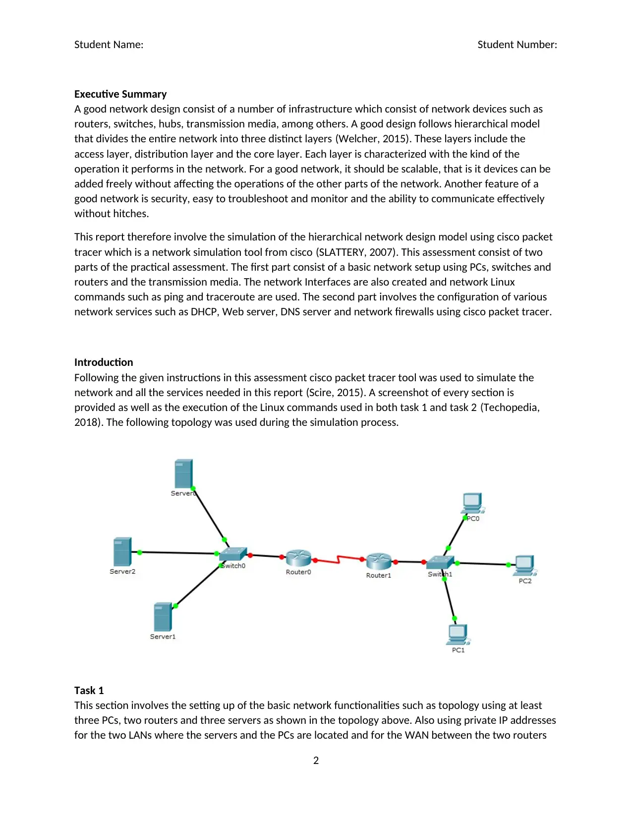
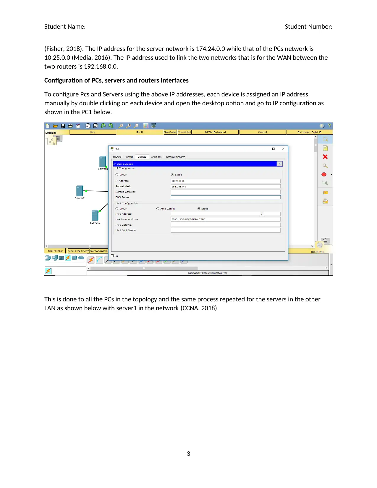
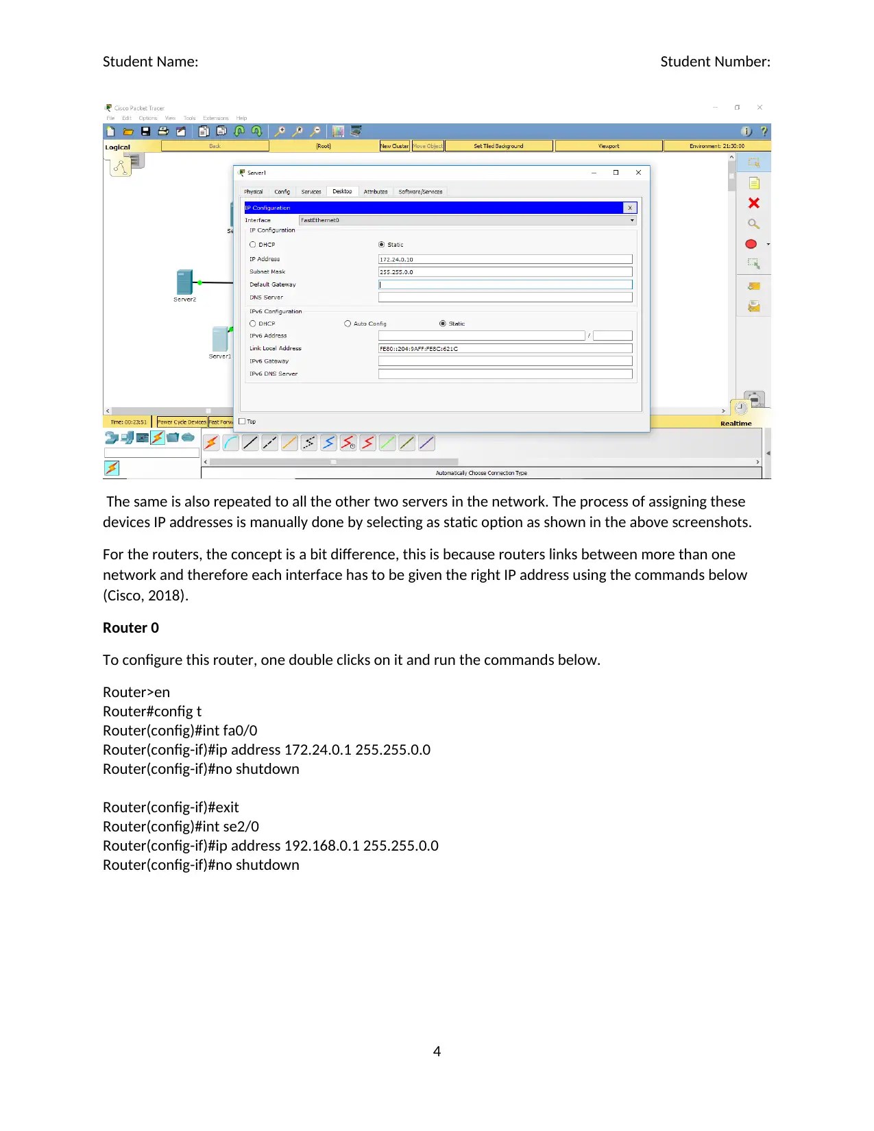
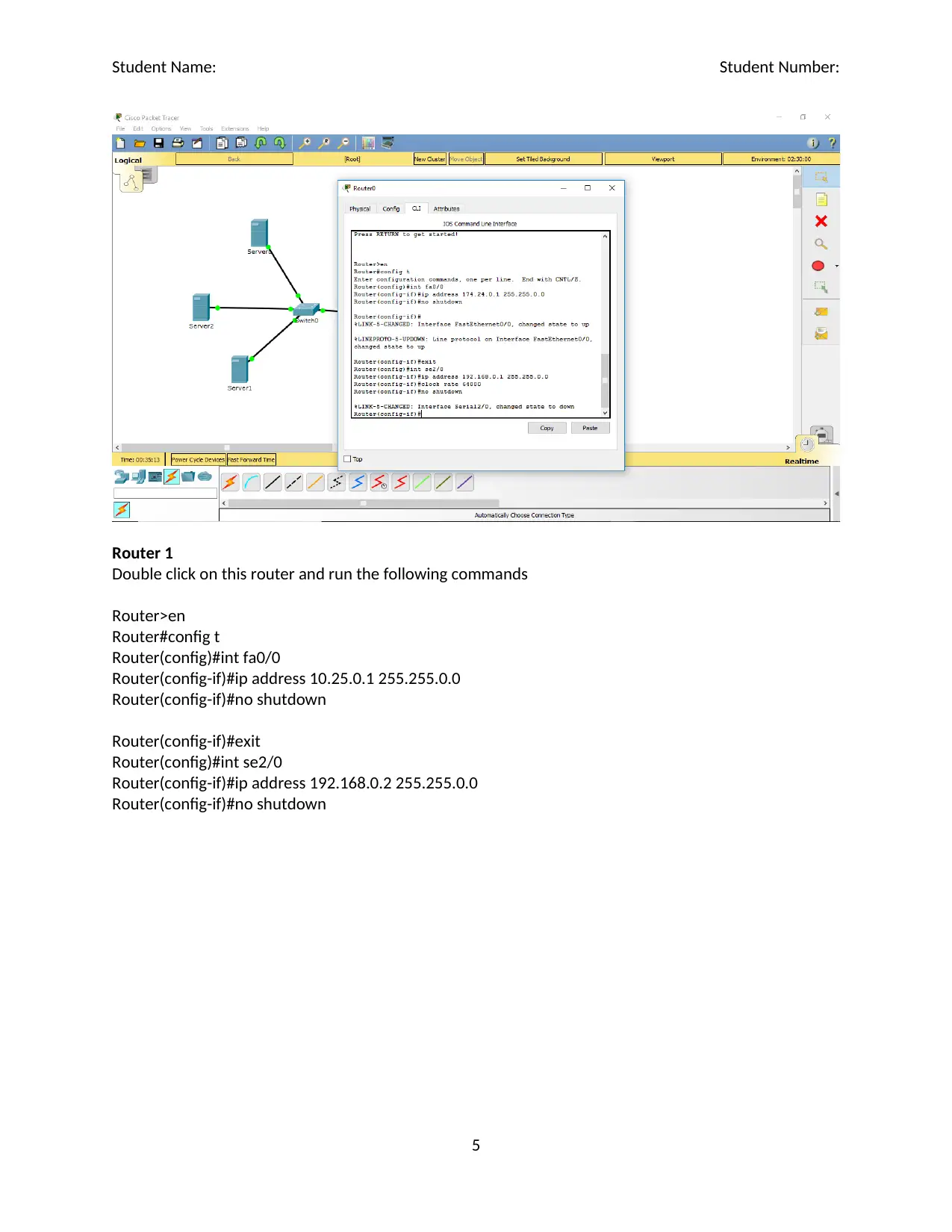
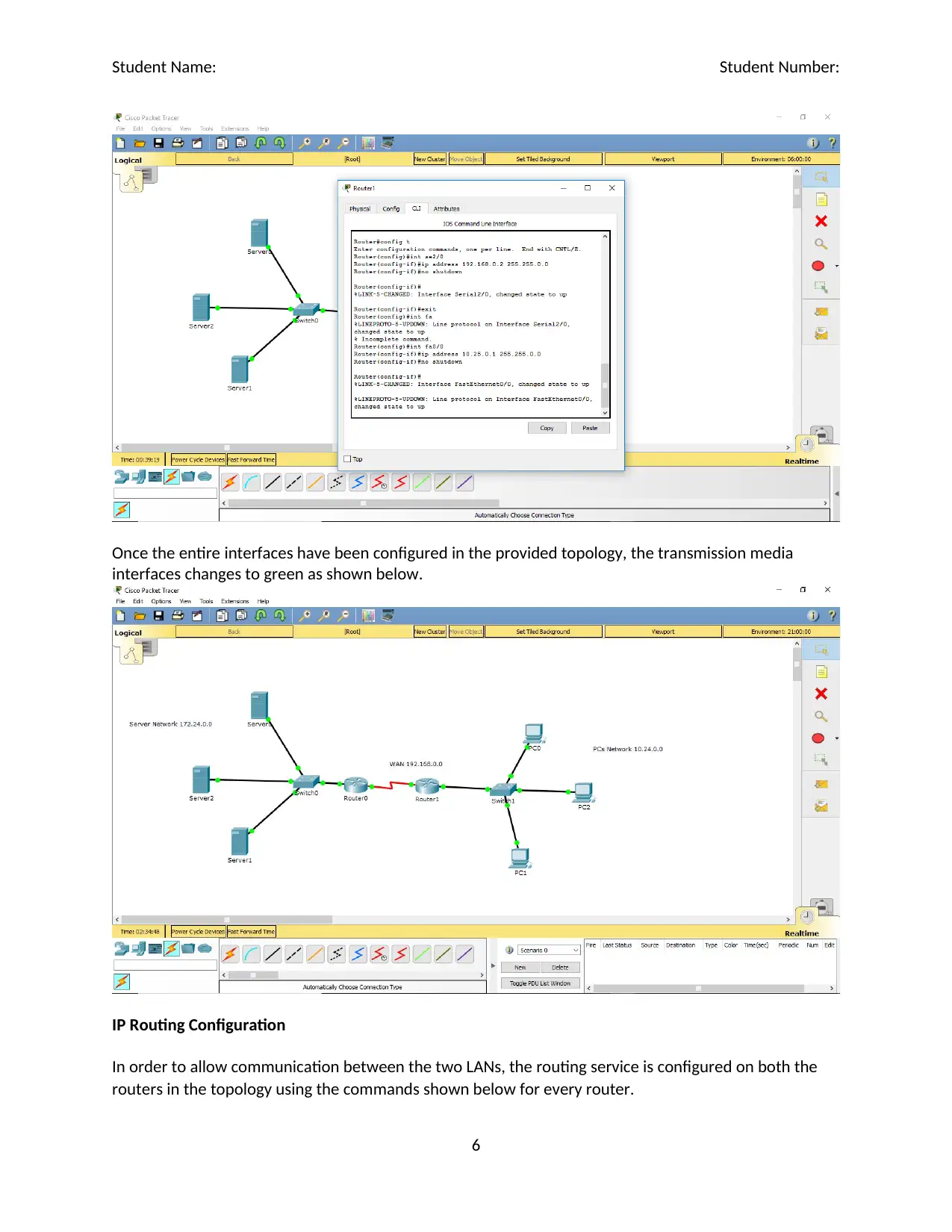
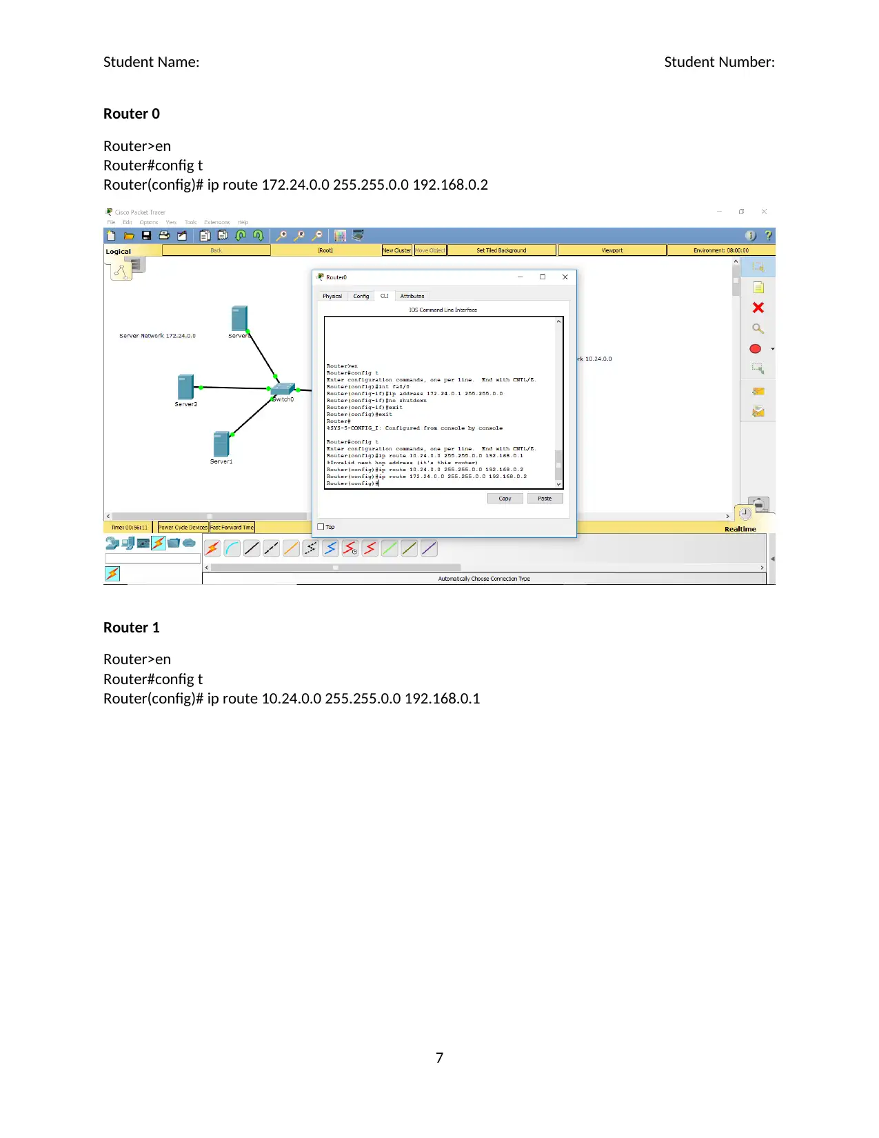
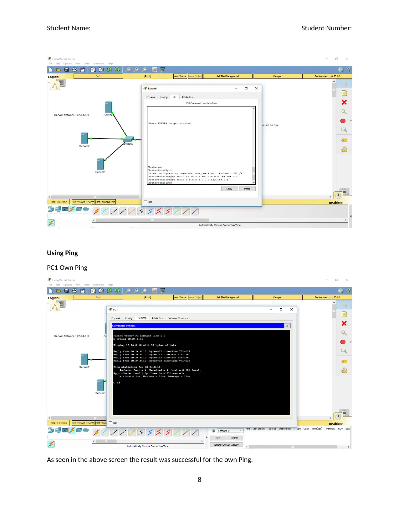
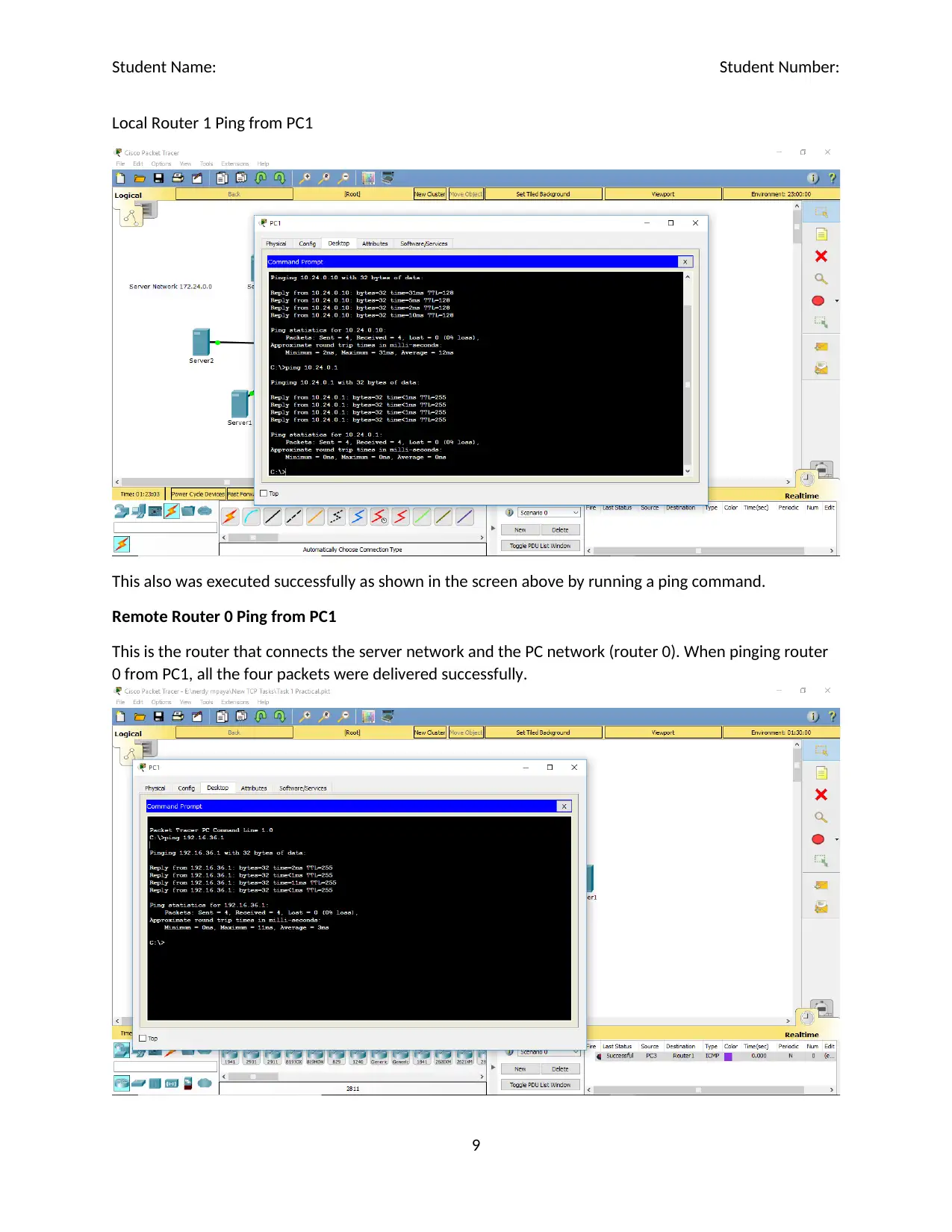
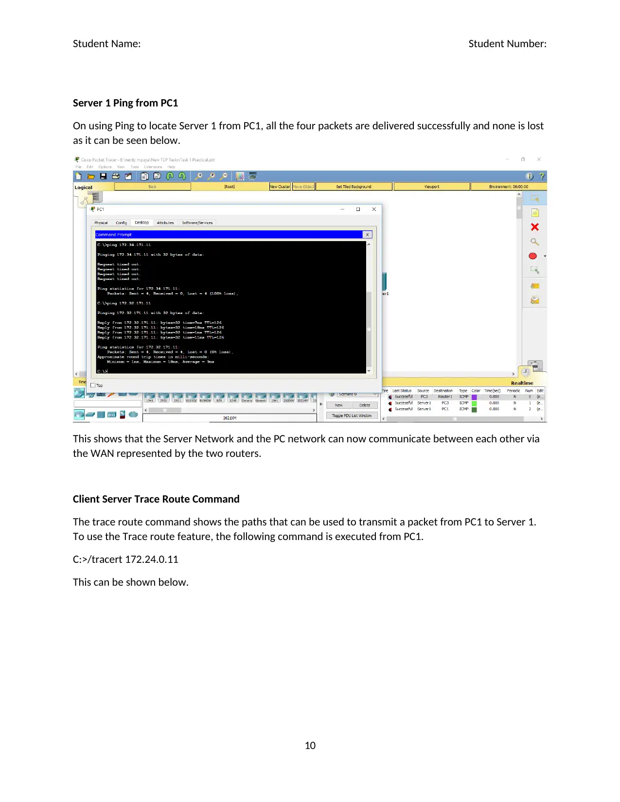
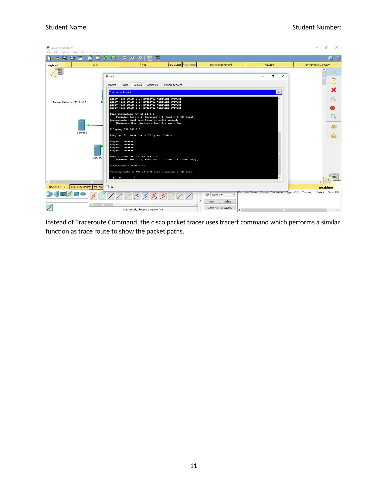
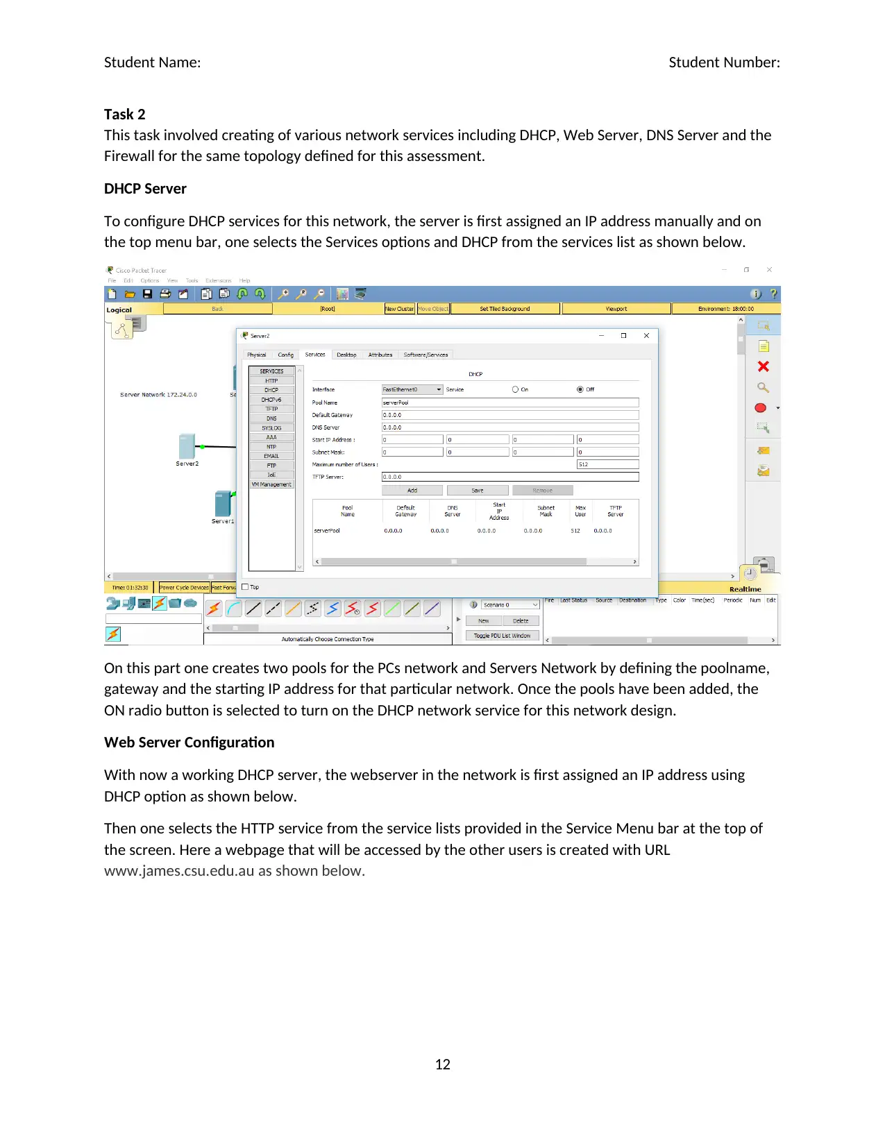
This practical assignment focuses on simulating a hierarchical network model using Cisco Packet Tracer, demonstrating key networking concepts and configurations. The solution details the setup of a network topology with PCs, routers, and servers, utilizing private IP addresses for LANs and a WAN. It covers the configuration of PC, server, and router interfaces, along with IP routing to enable communication between networks. The assignment also includes configuring network services such as DHCP, a web server, DNS server, and network firewalls, illustrating how to implement these services within the simulated environment. Linux commands like ping and traceroute are used to test network connectivity and trace packet paths, while firewall configurations are implemented to block TCP traffic. This comprehensive simulation provides a hands-on understanding of network design and configuration using Cisco Packet Tracer. Desklib offers similar solved assignments for students.

1 out of 17
Related Documents


Your All-in-One AI-Powered Toolkit for Academic Success.
+13062052269
info@desklib.com
Available 24*7 on WhatsApp / Email
![[object Object]](/_next/static/media/star-bottom.7253800d.svg)
Copyright © 2020–2026 A2Z Services. All Rights Reserved. Developed and managed by ZUCOL.