Career Episode 2 Report: Soap Sprayer and Dryer Control System Project
VerifiedAdded on 2020/03/16
|13
|1685
|58
Report
AI Summary
This report details a student's project on the development of a soap sprayer and dryer control system for an industrial plant, focusing on the application of Programmable Logic Controllers (PLCs) and Human Machine Interfaces (HMIs) to automate the soap production process. The project, conducted at N.E.D University of Engineering and Technology, involved designing a system to collect data from various points in the plant, monitor, control, and set off alarms. The student, acting as Team Leader, used SIMATIC S7-300 PLC and STEP7 programming software with ladder logic to automate electrochemical procedures. The report covers the project's objectives, which included designing the control system, collecting plant data, utilizing PLC for automation, and surveying other automation projects. The student's responsibilities included PLC configuration, hardware implementation, and HMI graphic design for both the pan and dryer areas. The report also addresses identified issues, such as the complexity of the user interface, and provides solutions like implementing a proper system hierarchy. The project incorporated PID controllers for precise control of soap ingredients, temperature, and pressure. The report concludes with a review of the project's contribution to increased production efficiency and reduced human errors, highlighting the use of collaborative work and literature surveys to enhance the student's knowledge in electronics engineering.
Competency Demonstration Report
Career Episode 2
Career Episode 2
Paraphrase This Document
Need a fresh take? Get an instant paraphrase of this document with our AI Paraphraser
CE 2.1 Project Information
Name of the project: Soap sprayer and dryer control system
Location of the project: Karachi
Project Duration: (Please fill)
Organization: N.E.D University of Engineering and Technology
Role and Designation during the time: Team Leader
CE 2.2 Project Background
CE 2.2.1 Characteristics of the project
I had conducted the project on development of soap spraying and drying control system
which is considered as the mostly used industrial process for formation of soap. I had designed
this project to collect information from different points of industrial plant and present control
area that permits to monitor, control and set off alarms. Human Machine Interface (HMI)
presented the collected data from operating system and permitted the operator to take quick
decisions. The feature of this system is to reduce higher operational cost, improvement over
entire performance of industry plant and permit remote monitoring of data.
CE 2.2.2 Objectives developed for the project
Following are the objectives of this project study:
To design of soap sprayer and dryer control system
To collect information from different points of industrial plant
To use of PLC for automation of industrial electromechanical procedures
To conduct of survey of other PLC SCADA based automation projects
CE 2.2.3 My Area of work
I had involved in the project to use PLC for automating the electrochemical procedures of
the industrial plant. I had chosen SIMATIC S7-300 as PLC for our project work. PLC is
developed for substituting the relay logic systems. I had configured it with use of ladder logic. I
had focused to meet the project aim of developing commands on the control system with less
training. I had analyzed that use of microcontroller for design of soap sprayer and dryer control
system is suitable where there is achievement of mass production such that expansion price
would outweigh the sales.
CE 2.2.4 Project Group
ProjectSupervisorInternalSupervisorElectronicsEngineerOperatorExternalSupervisor
⊘ This is a preview!⊘
Do you want full access?
Subscribe today to unlock all pages.

Trusted by 1+ million students worldwide

Figure 1: People involved in the project
Paraphrase This Document
Need a fresh take? Get an instant paraphrase of this document with our AI Paraphraser
CE 2.2.5 My responsibilities throughout the project
My main responsibility is to conduct this project with use of PLC microcontroller such as
SIMATIC S7-300 for serving universal definitive automation system. I had chosen this particular
PLC as it is designed for system solutions. This system secures of conservation cost and
investment. I had chosen STEP7 as a programming software for hardware configuration,
programming, operational functions, documentation and communication.
CE 2.3 Distinctive Activity
CE 2.3.1 Comprehending the Theory of the project
I had divided the project work into two parts: Pan Area and Dryer Area.
Pan Area: I had analyzed the pan area such as I had taken six pans (2, 3, 9, 10, 16 and
17). The concept behind working with the pan is that certain soap is made and release of
ingredients from the storage pots upon the valves. The operator set point on weight transmitter
(WT01) for overhead the load cell. It helps to verify if limit switch (LS01) for the pan is open.
After setting of the charge weight, pneumatic actuated valve (VA01) is opened to release the
material from the pan. The valve is interlocked with WT01, and shut once set point weight of
material is dropped. Recirculation is started when the operator selected Recirculation ON’ on
pump, then it opened two actuated three-way valves (VA08 & VA09) back into the pan. At the
screen of the pan, I had observed both bottom and side temperatures (TI01 & TI02) at the time.
Dryer area: I had selected screen of the dryer to start and set the temperature (T101) and
from that screen, liquid soap is fed into the dryer; TI01 is interlocked with the steam control
valve (VA100) at the heat exchanger inlet, VA100 should not unlock in anticipation of soap feed
pump (e.g. PU14) started running. I had selected recirculation that shut valve (VA101) and open
the recycle valve (VA102). I had started the motor for spray chamber; the motor for the dust
extruder is interlocked with spray chamber motor plus started automatically. The feeding valve
(VA101) opened the motor, then it started and the operator can manually start the noodle motor
(M03).
CE 2.3.2 Engineering Knowledge and Skills applied in the project
I have knowledge about the PLC hardware, its mechanism and respective functionality to
achieve the project objectives and reduce the issues into the project work. I have knowledge to
do project implementation for pan area and dryer area using graphic designer in HMI.
CE 2.3.3 Accomplishment and task performed
I had performed the graphic designer of the pan and dryer area in HMI. I had followed
some of the steps to do my work:
PAN AREA:
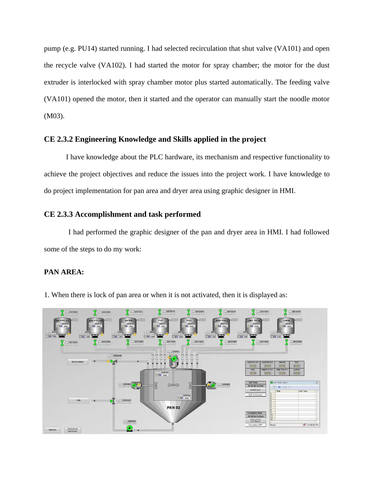
1. When there is lock of pan area or when it is not activated, then it is displayed as:
⊘ This is a preview!⊘
Do you want full access?
Subscribe today to unlock all pages.

Trusted by 1+ million students worldwide
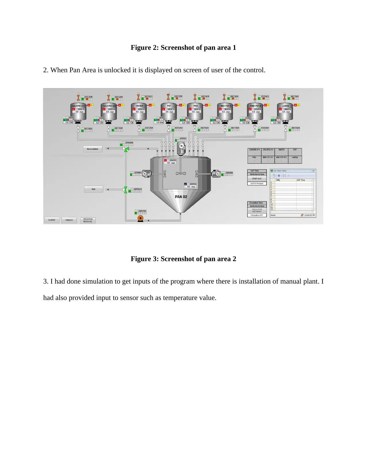
Figure 2: Screenshot of pan area 1
2. When Pan Area is unlocked it is displayed on screen of user of the control.
Figure 3: Screenshot of pan area 2
3. I had done simulation to get inputs of the program where there is installation of manual plant. I
had also provided input to sensor such as temperature value.
2. When Pan Area is unlocked it is displayed on screen of user of the control.
Figure 3: Screenshot of pan area 2
3. I had done simulation to get inputs of the program where there is installation of manual plant. I
had also provided input to sensor such as temperature value.
Paraphrase This Document
Need a fresh take? Get an instant paraphrase of this document with our AI Paraphraser
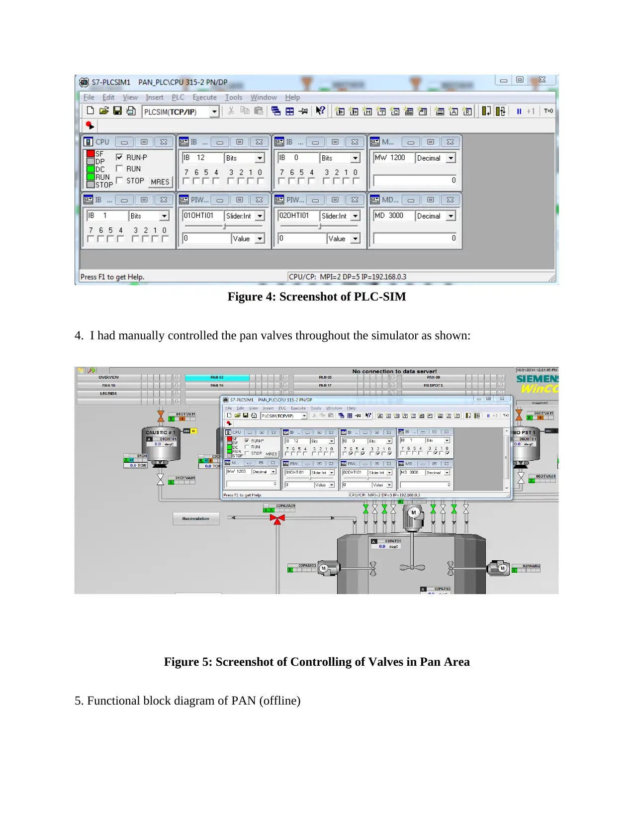
Figure 4: Screenshot of PLC-SIM
4. I had manually controlled the pan valves throughout the simulator as shown:
Figure 5: Screenshot of Controlling of Valves in Pan Area
5. Functional block diagram of PAN (offline)
4. I had manually controlled the pan valves throughout the simulator as shown:
Figure 5: Screenshot of Controlling of Valves in Pan Area
5. Functional block diagram of PAN (offline)
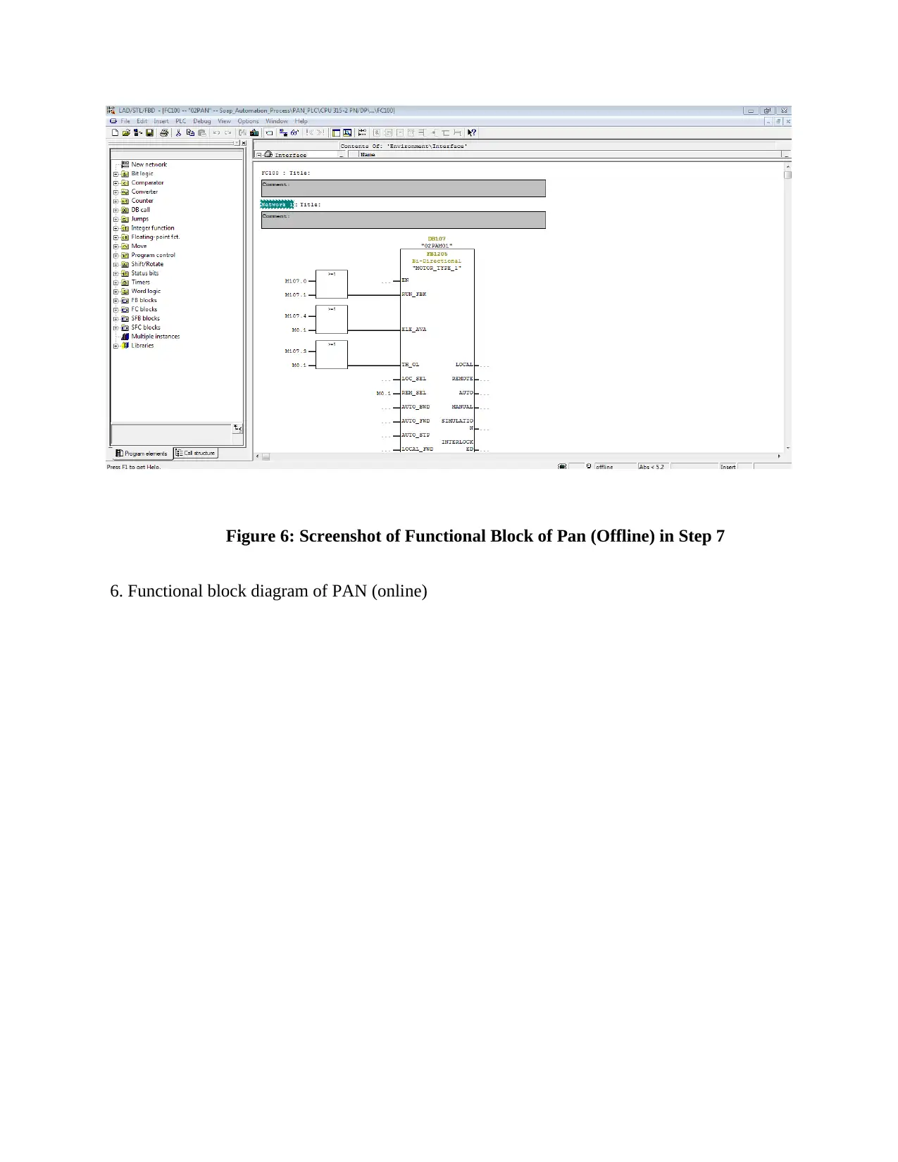
Figure 6: Screenshot of Functional Block of Pan (Offline) in Step 7
6. Functional block diagram of PAN (online)
6. Functional block diagram of PAN (online)
⊘ This is a preview!⊘
Do you want full access?
Subscribe today to unlock all pages.

Trusted by 1+ million students worldwide
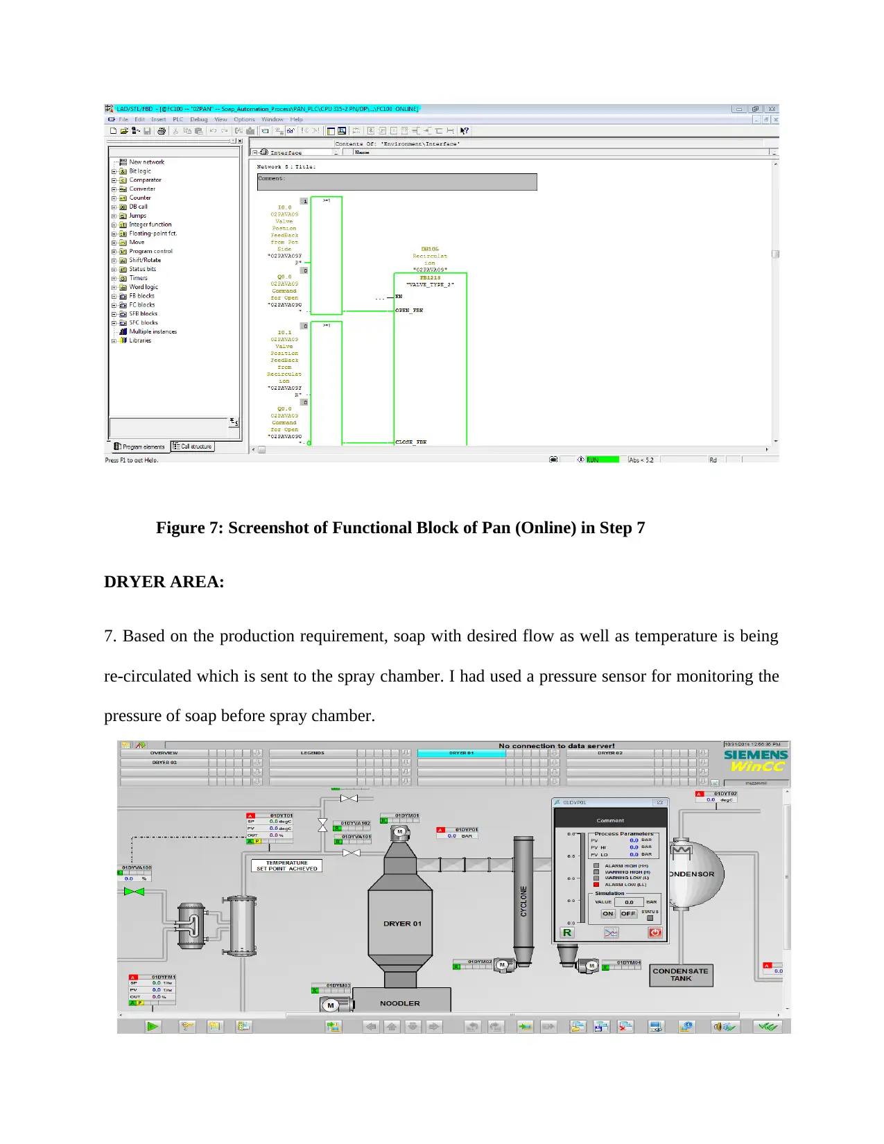
Figure 7: Screenshot of Functional Block of Pan (Online) in Step 7
DRYER AREA:
7. Based on the production requirement, soap with desired flow as well as temperature is being
re-circulated which is sent to the spray chamber. I had used a pressure sensor for monitoring the
pressure of soap before spray chamber.
DRYER AREA:
7. Based on the production requirement, soap with desired flow as well as temperature is being
re-circulated which is sent to the spray chamber. I had used a pressure sensor for monitoring the
pressure of soap before spray chamber.
Paraphrase This Document
Need a fresh take? Get an instant paraphrase of this document with our AI Paraphraser
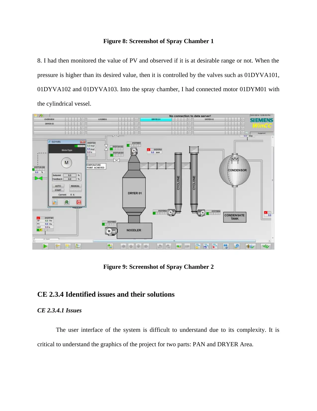
Figure 8: Screenshot of Spray Chamber 1
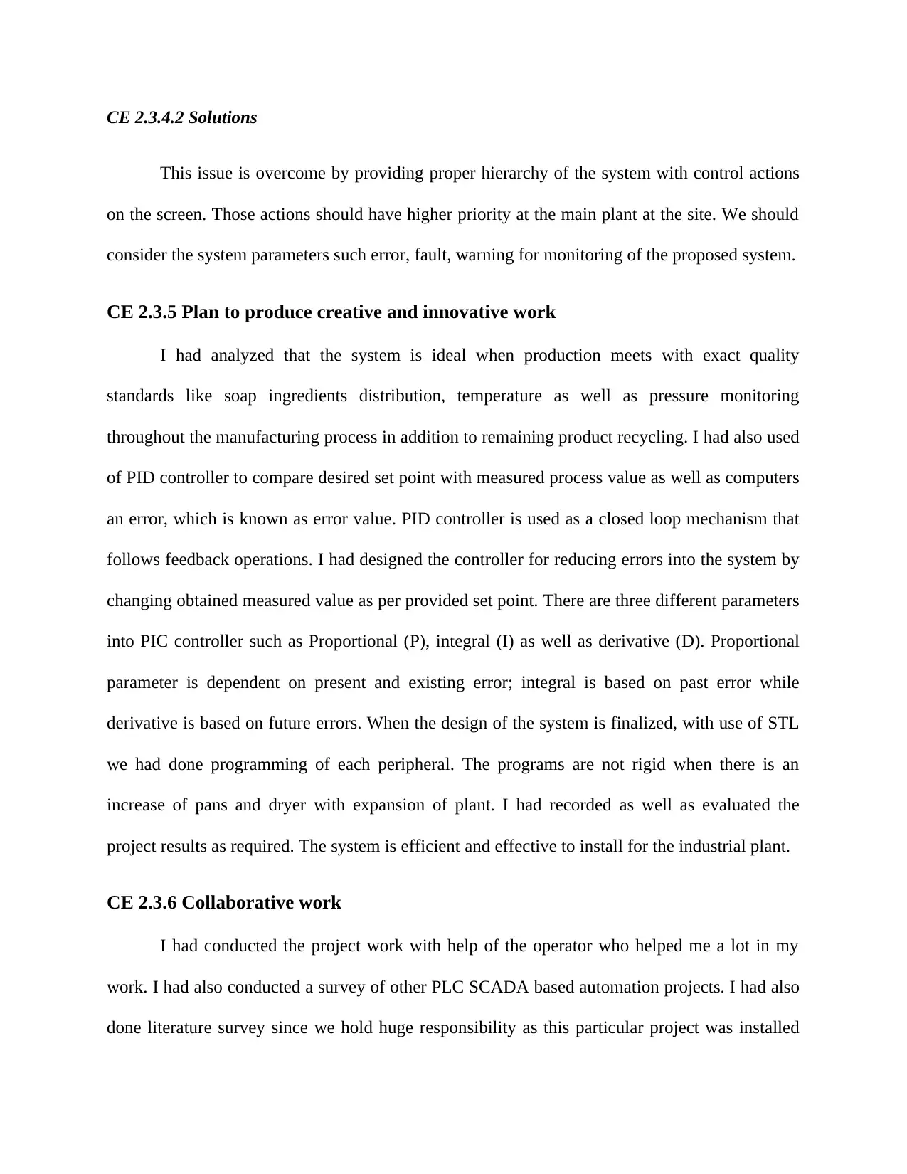
8. I had then monitored the value of PV and observed if it is at desirable range or not. When the
pressure is higher than its desired value, then it is controlled by the valves such as 01DYVA101,
01DYVA102 and 01DYVA103. Into the spray chamber, I had connected motor 01DYM01 with
the cylindrical vessel.
Figure 9: Screenshot of Spray Chamber 2
CE 2.3.4 Identified issues and their solutions
CE 2.3.4.1 Issues
The user interface of the system is difficult to understand due to its complexity. It is
critical to understand the graphics of the project for two parts: PAN and DRYER Area.
CE 2.3.4.2 Solutions
This issue is overcome by providing proper hierarchy of the system with control actions
on the screen. Those actions should have higher priority at the main plant at the site. We should
consider the system parameters such error, fault, warning for monitoring of the proposed system.
CE 2.3.5 Plan to produce creative and innovative work
I had analyzed that the system is ideal when production meets with exact quality
standards like soap ingredients distribution, temperature as well as pressure monitoring
throughout the manufacturing process in addition to remaining product recycling. I had also used
of PID controller to compare desired set point with measured process value as well as computers
an error, which is known as error value. PID controller is used as a closed loop mechanism that
follows feedback operations. I had designed the controller for reducing errors into the system by
changing obtained measured value as per provided set point. There are three different parameters
into PIC controller such as Proportional (P), integral (I) as well as derivative (D). Proportional
parameter is dependent on present and existing error; integral is based on past error while
derivative is based on future errors. When the design of the system is finalized, with use of STL
we had done programming of each peripheral. The programs are not rigid when there is an
increase of pans and dryer with expansion of plant. I had recorded as well as evaluated the
project results as required. The system is efficient and effective to install for the industrial plant.
CE 2.3.6 Collaborative work
I had conducted the project work with help of the operator who helped me a lot in my
work. I had also conducted a survey of other PLC SCADA based automation projects. I had also
done literature survey since we hold huge responsibility as this particular project was installed
⊘ This is a preview!⊘
Do you want full access?
Subscribe today to unlock all pages.

Trusted by 1+ million students worldwide
1 out of 13
Related Documents
Your All-in-One AI-Powered Toolkit for Academic Success.
+13062052269
info@desklib.com
Available 24*7 on WhatsApp / Email
![[object Object]](/_next/static/media/star-bottom.7253800d.svg)
Unlock your academic potential
Copyright © 2020–2026 A2Z Services. All Rights Reserved. Developed and managed by ZUCOL.


