logo

Hydraulic Design for Gravity-Driven Piping System: Calculations, Pipe Selection, and Friction Analysis

12 Pages1492 Words495 Views
   

Added on  2023-04-25

About This Document

The given paragraph describes the hydraulic design for a gravity-driven piping system. It includes calculations for determining the diameter of the pipe, selecting the pipe material, calculating the gradient, friction losses, and pressure drop. The flow is determined to be turbulent, and the friction coefficient is calculated using the Blasius equation. The paragraph also mentions the magnitude and location of the hydrostatic force acting on the gate valve.

Hydraulic Design for Gravity-Driven Piping System: Calculations, Pipe Selection, and Friction Analysis

   Added on 2023-04-25

ShareRelated Documents
Hydraulic Design Calculations 1
Hydraulic Design for Gravity driven Piping System
By
Student Name
Name of Class
Professsor
Name of Institution
(Date)
Hydraulic Design for Gravity-Driven Piping System: Calculations, Pipe Selection, and Friction Analysis_1
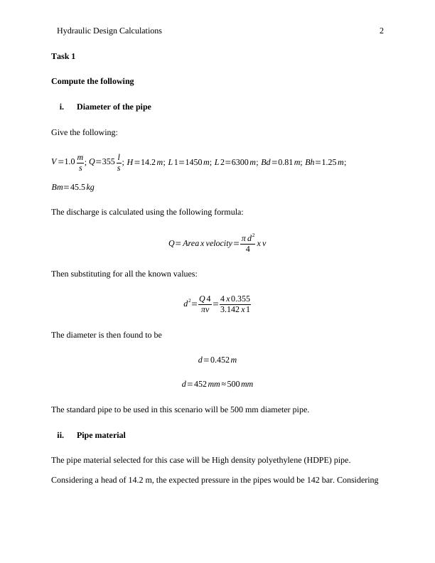
Hydraulic Design Calculations 2
Task 1
Compute the following
i. Diameter of the pipe
Give the following:
V =1.0 m
s ; Q=355 l
s ; H=14.2 m; L 1=1450 m; L 2=6300 m; Bd=0.81 m; Bh=1.25 m;
Bm=45.5 kg
The discharge is calculated using the following formula:
Q= Area x velocity= π d2
4 x v
Then substituting for all the known values:
d2= Q 4
πv = 4 x 0.355
3.142 x 1
The diameter is then found to be
d=0.452 m
d=452 mm 500 mm
The standard pipe to be used in this scenario will be 500 mm diameter pipe.
ii. Pipe material
The pipe material selected for this case will be High density polyethylene (HDPE) pipe.
Considering a head of 14.2 m, the expected pressure in the pipes would be 142 bar. Considering
Hydraulic Design for Gravity-Driven Piping System: Calculations, Pipe Selection, and Friction Analysis_2
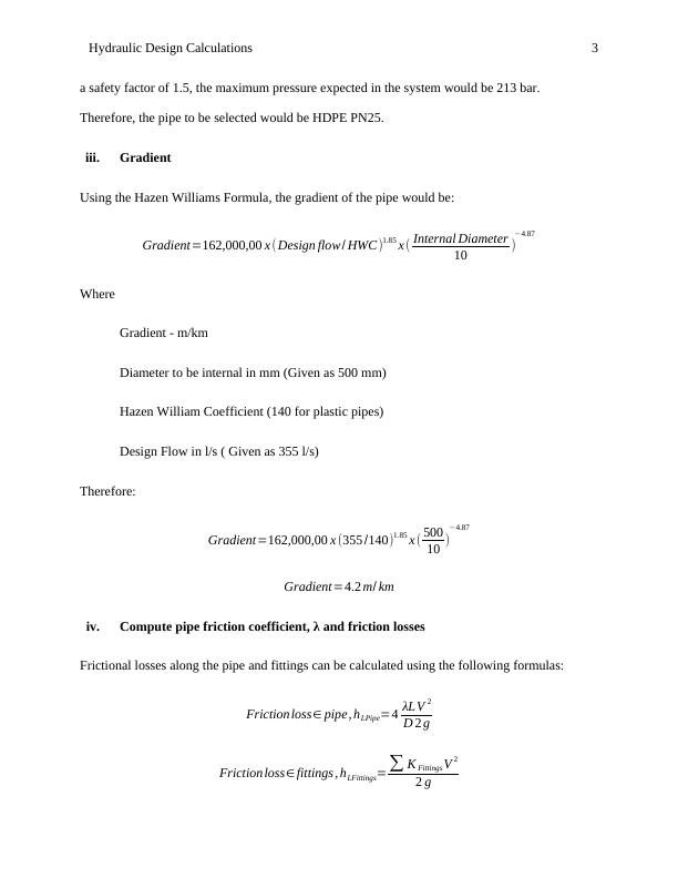
Hydraulic Design Calculations 3
a safety factor of 1.5, the maximum pressure expected in the system would be 213 bar.
Therefore, the pipe to be selected would be HDPE PN25.
iii. Gradient
Using the Hazen Williams Formula, the gradient of the pipe would be:
Gradient=162,000,00 x (Design flow/ HWC)1.85 x ( Internal Diameter
10 )
4.87
Where
Gradient - m/km
Diameter to be internal in mm (Given as 500 mm)
Hazen William Coefficient (140 for plastic pipes)
Design Flow in l/s ( Given as 355 l/s)
Therefore:
Gradient=162,000,00 x (355 /140)1.85 x ( 500
10 )
4.87
Gradient=4.2 m/ km
iv. Compute pipe friction coefficient, λ and friction losses
Frictional losses along the pipe and fittings can be calculated using the following formulas:
Friction loss pipe, hLPipe=4 λLV 2
D 2 g
Friction loss fittings , hLFittings= K Fittings V 2
2 g
Hydraulic Design for Gravity-Driven Piping System: Calculations, Pipe Selection, and Friction Analysis_3
Hydraulic Design Calculations 4
Where
V - Velocity
D - Inner diameter of pipe
L - Pipe Length
g – Gravity
K - Resistance coefficient for fittings
λ - Pipe friction coefficient
hL - Pressure drop;
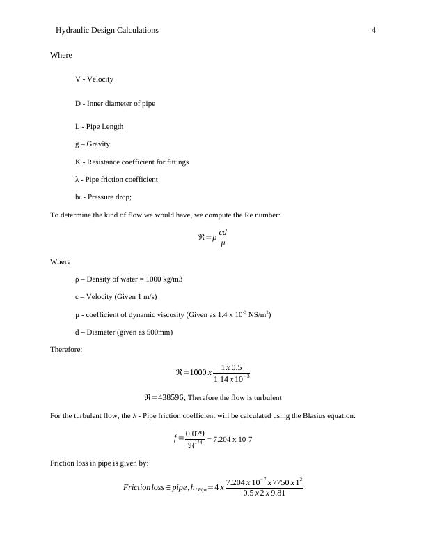
To determine the kind of flow we would have, we compute the Re number:
=ρ cd
μ
Where
ρ – Density of water = 1000 kg/m3
c – Velocity (Given 1 m/s)
μ - coefficient of dynamic viscosity (Given as 1.4 x 10⁻³ NS/m2)
d – Diameter (given as 500mm)
Therefore:
=1000 x 1 x 0.5
1.14 x 103
=438596; Therefore the flow is turbulent
For the turbulent flow, the λ - Pipe friction coefficient will be calculated using the Blasius equation:
f = 0.079
1 / 4 = 7.204 x 10⁻⁷
Friction loss in pipe is given by:
Friction loss pipe, hLPipe=4 x 7.204 x 107 x 7750 x 12
0.5 x 2 x 9.81
Hydraulic Design for Gravity-Driven Piping System: Calculations, Pipe Selection, and Friction Analysis_4

End of preview

Want to access all the pages? Upload your documents or become a member.

Related Documents
Solutions 1.1 Provided information V = 1.15 m/s Q =315 L/s =
|5
|485
|308

Pump System Design - Task 1-5
|14
|1189
|440

Fluid Mechanics: Solutions for Pump Selection, System Characteristic Curve, NPSH Calculation, and Pipe Selection
|11
|2113
|126