Hydraulic for civil engineering
VerifiedAdded on 2022/08/14
|12
|2300
|13
AI Summary
Contribute Materials
Your contribution can guide someone’s learning journey. Share your
documents today.
Hydraulic for civil engineering
Introduction
Water is always considered as a vital and essential commodity that human being and animals in
general cannot forego. In order to ensure this essential commodity would reach everyone either
in towns or rural areas its supply and distributions through pipes or open channel would always
be considered.
Several factors would always be considered while distributing water in each and every section of
a particular region. In order to avoid barriers that may be encountered by the water being
distributed calculations of the rate of water, the size of the pipes and open channel, the slope of
the land, the pressure exerted and factors that may cause water flow resistance would be
calculated and its effectiveness ensured.
The system of water distribution that facilitates transportation of fresh drinking water from a
treatment plant would consists of pumps, pipes, storage tanks, valves, meters, fittings, reservoirs
and other appurtenances.
The system always would require maintenances of its hydraulic integrity in order to ensure that
water with high acceptable standards of both the quantity and quality would be delivered. The
vital hydraulic integrity element would be existence of adequate pressure of water inside the
distribution pipes. The low water pressure would indicate that either there would be significant
leakages, pipes have break, head loss on the walls of the pipes are excessive, failure of valves or
pressure have surge. The occurrence of the low pressure would deter the delivery of water which
may increase the contamination risks through intrusion. The other hydraulic element would be
detention time of water within the distribution system. Large detention time would be as a result
of low flows which may result to accumulation of sediments inside the pipes and therefore
reducing the disinfectant residual, in addition the sediment deposits would increase pipe
roughness and this would increase the cost of pumping and reduce the capacity of hydraulic.
Objectives
The core objectives that would be achieved at the end study would include
1. To determine hydrostatic and hydrodynamic problems
2. To determine forces exerted on fluids on rest and in motion
3. To determine appropriate sizes of water distribution pipes
4. To determine hydrostatic pressure that would be exerted on substructures.
Secure Best Marks with AI Grader
Need help grading? Try our AI Grader for instant feedback on your assignments.
Calculations
Task 1
ai) Pressure in the pipe
Height = 100 m
Pressure = gravitational pull * density of water * height (Zhang and Sarica, 2011)
P = ρ * g * h
Where,
Density of water = 1000 kg/m3
g = 9.81 N/kg
P = 9.81 * 1000 * 100
= 981,000 N/m2
= 9.81 bar
ii) Pressure in the open channel
Height = 100 m
Pressure = gravitational pull * density of water * height
P = ρ * g * h
Where,
Density of water = 1000 kg/m3
g = 9.81 N/kg
P = 9.81 * 1000 * 100
= 981,000 N/m2
= 9.81 bar
iii) Explanation of equivalent in water presssure in both the pipe and open channel
The formula for calculating pressure in liquid normally would be presented as, P = ρ * g * h, the
variable ‘h’ is an indpendent variable with constant values of ρ and g. since the height has not
changed then the pressure would remain the same in both the cases (Cheng and Nguyen, 2011).
b) Types of forces that resists water flow in pipes
i) Viscosity
Viscosity refers to the resistance measure of a fluid to flow. It describes the existence ofan
internal friction of the moving fluid along the pipe. Always fluids with large viscosity would
resist fluid motion since the molecular nature of the fluid would result to large internal friction.
Similarly, fluids with low viscosity would result to less friction on the liquid flow (Nejad, Berg
and Ringen, 2011).
ii) Boundaries
Each boundary layer would have a shear stress equivalent to τ and this stress would increase by
dτ on each layer based on the larger thickness of δ (Massey, Bernards and Ward-Smith, 2012)
c) Effects of water temperatures on forces that resists water flow in pipes
Increase in temperature would decrease viscosity and boundaries of the liquid throuh impacting
water molecular structure, therefore, molecules would move faster and overcome molecules
binding force (Holmes, Parker and Povey, 2011).
d) Difference between laminar and turbulent flow
In lamina flow
Fluids normally would flow in the same directions
No fluid mixing would occur
It occurs when the fluid moves slow, the depth of the fluid is shallow and the fluid is very
viscous
It occurs when Rehnolds number would be high
In turbulent flow
It occurs when Rehnolds number would be high
It occurs when the flow have a fluctuated velocity and high disorder
e) Reynolds number and its relation to turbulent flow
Reynolds number is defined as the ratio between inertial forces to viscous forces (Niu et al.,
2017)
This would be represented as;
Re = V avg D
v = ρV avg D
μ
Where,
Vavg = average velocity
D = diameter
v = μ
ρ = kinematic velocity
The flow in circular pipes would be turbulent for Re ≥ 4000
f) Boundary layer and how it is affected by water flow surface roughness
A fluid layer would be called boundary layer when its velocity would be affected by boundary
shear (Niu,Örlü and Schlatter, 2011).
As the roughness laminar layer increases in thickness, it would become unstable and
thereafter be able to be transformed to turbulent boundary layer where the fluid particles
would start moving haphazardly
g) Reduction of water flow resistance in pipes and open channel
It would be reduced by reducing viscosity
h) Methods involved in supply addition water in town without disrupting the current
water supply
An additional supply of water would only be piped in the town when more additional and larger
reservoirs would be constructed and their supplies directed to the initial pipes distributions
Task 2
a) Calculation of maximum depth of flow using Manning formula
Open channel
Manning formula (Song, et al., 2016)
Q = A R
2
3
h S
1
2
n
Wetted perimeter
P = L + 2w
P = 2 + 2w
Area = A = l * W
= 2 * w
= 2w
Rh = A/P
Secure Best Marks with AI Grader
Need help grading? Try our AI Grader for instant feedback on your assignments.
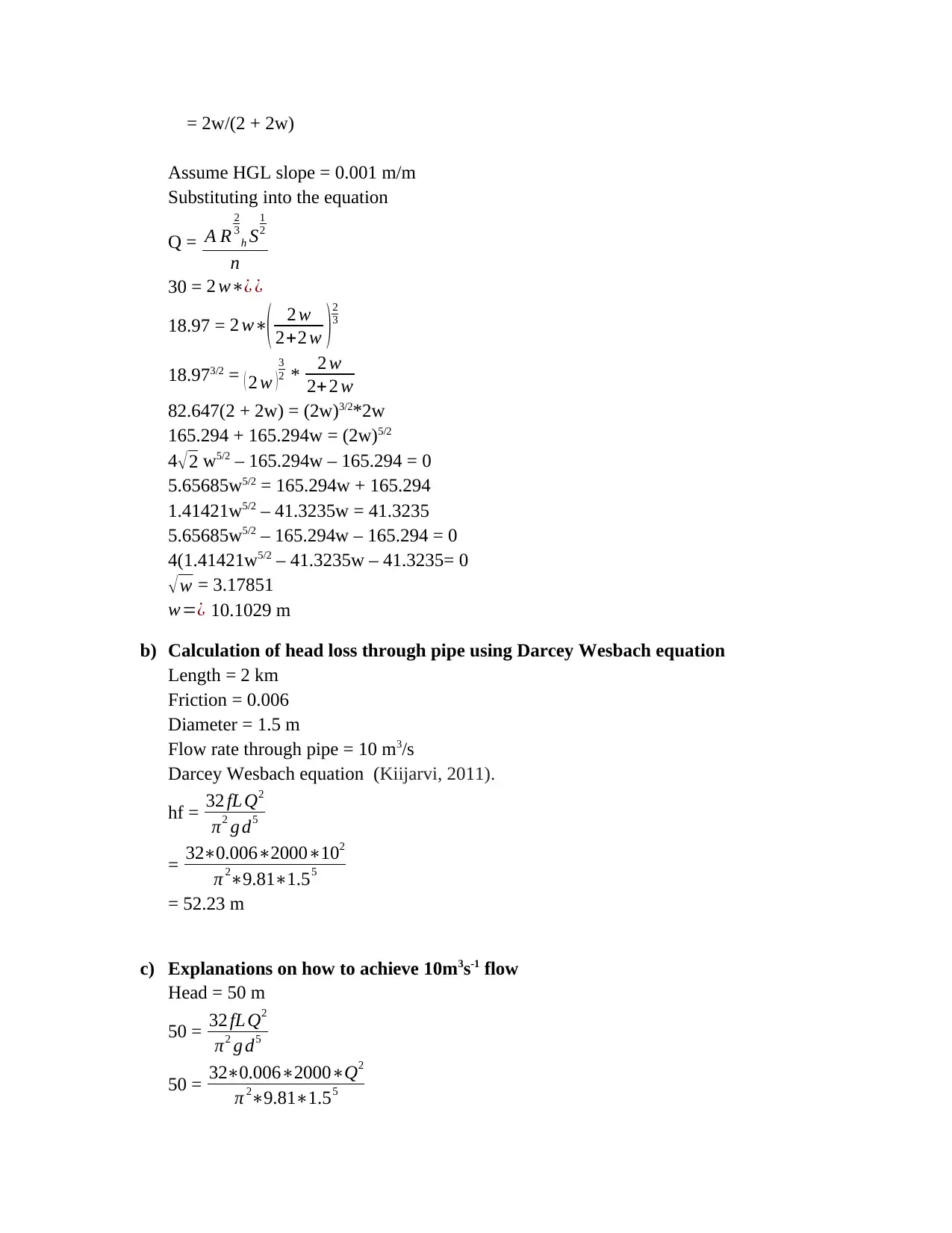
= 2w/(2 + 2w)
Assume HGL slope = 0.001 m/m
Substituting into the equation
Q = A R
2
3
h S
1
2
n
30 = 2 w∗¿ ¿
18.97 = 2 w∗( 2 w
2+2 w ) 2
3
18.973/2 = ( 2 w )
3
2 * 2 w
2+2 w
82.647(2 + 2w) = (2w)3/2*2w
165.294 + 165.294w = (2w)5/2
4√2 w5/2 – 165.294w – 165.294 = 0
5.65685w5/2 = 165.294w + 165.294
1.41421w5/2 – 41.3235w = 41.3235
5.65685w5/2 – 165.294w – 165.294 = 0
4(1.41421w5/2 – 41.3235w – 41.3235= 0
√ w = 3.17851
w=¿ 10.1029 m
b) Calculation of head loss through pipe using Darcey Wesbach equation
Length = 2 km
Friction = 0.006
Diameter = 1.5 m
Flow rate through pipe = 10 m3/s
Darcey Wesbach equation (Kiijarvi, 2011).
hf = 32 fL Q2
π2 g d5
= 32∗0.006∗2000∗102
π 2∗9.81∗1.55
= 52.23 m
c) Explanations on how to achieve 10m3s-1 flow
Head = 50 m
50 = 32 fL Q2
π2 g d5
50 = 32∗0.006∗2000∗Q2
π 2∗9.81∗1.55
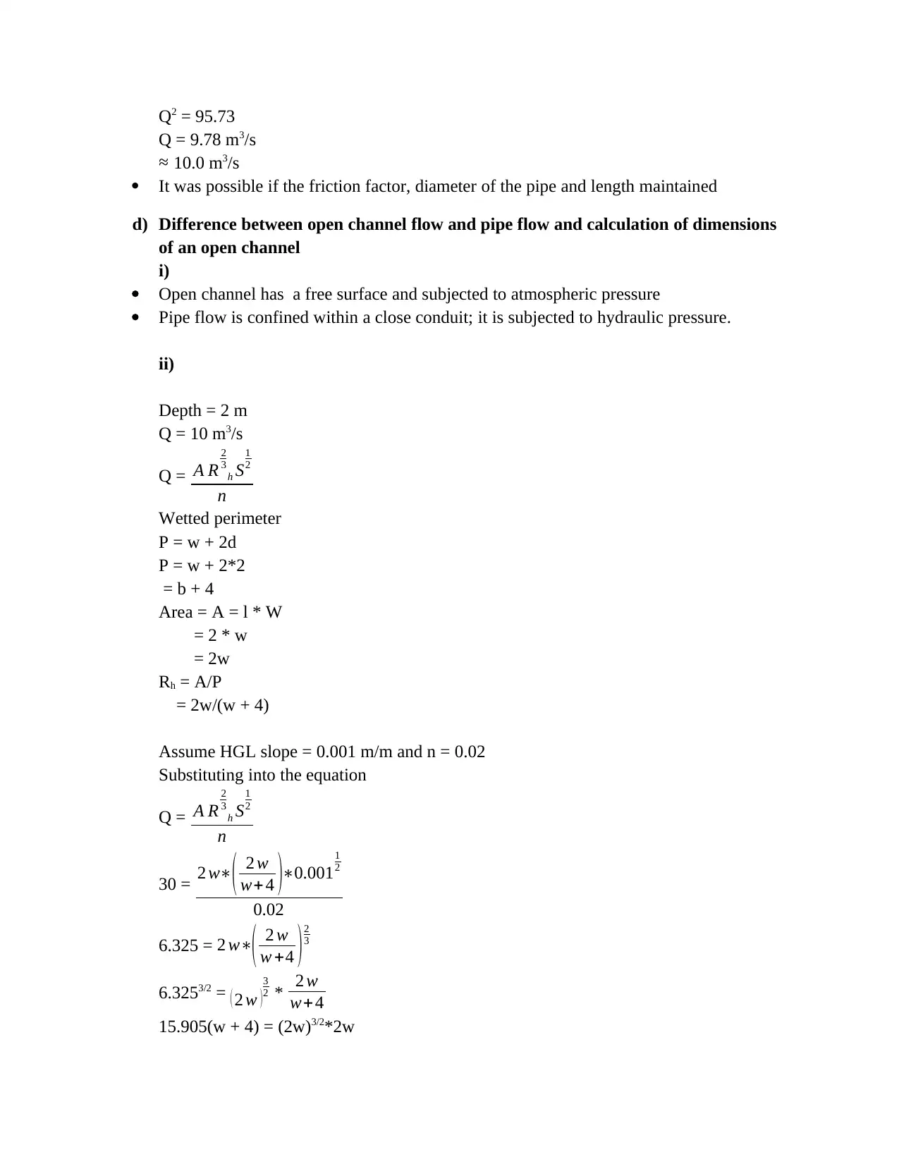
Q2 = 95.73
Q = 9.78 m3/s
≈ 10.0 m3/s
It was possible if the friction factor, diameter of the pipe and length maintained
d) Difference between open channel flow and pipe flow and calculation of dimensions
of an open channel
i)
Open channel has a free surface and subjected to atmospheric pressure
Pipe flow is confined within a close conduit; it is subjected to hydraulic pressure.
ii)
Depth = 2 m
Q = 10 m3/s
Q = A R
2
3
h S
1
2
n
Wetted perimeter
P = w + 2d
P = w + 2*2
= b + 4
Area = A = l * W
= 2 * w
= 2w
Rh = A/P
= 2w/(w + 4)
Assume HGL slope = 0.001 m/m and n = 0.02
Substituting into the equation
Q = A R
2
3
h S
1
2
n
30 = 2 w∗( 2 w
w+ 4 )∗0.001
1
2
0.02
6.325 = 2 w∗( 2 w
w +4 ) 2
3
6.3253/2 = ( 2 w )
3
2 * 2 w
w+4
15.905(w + 4) = (2w)3/2*2w
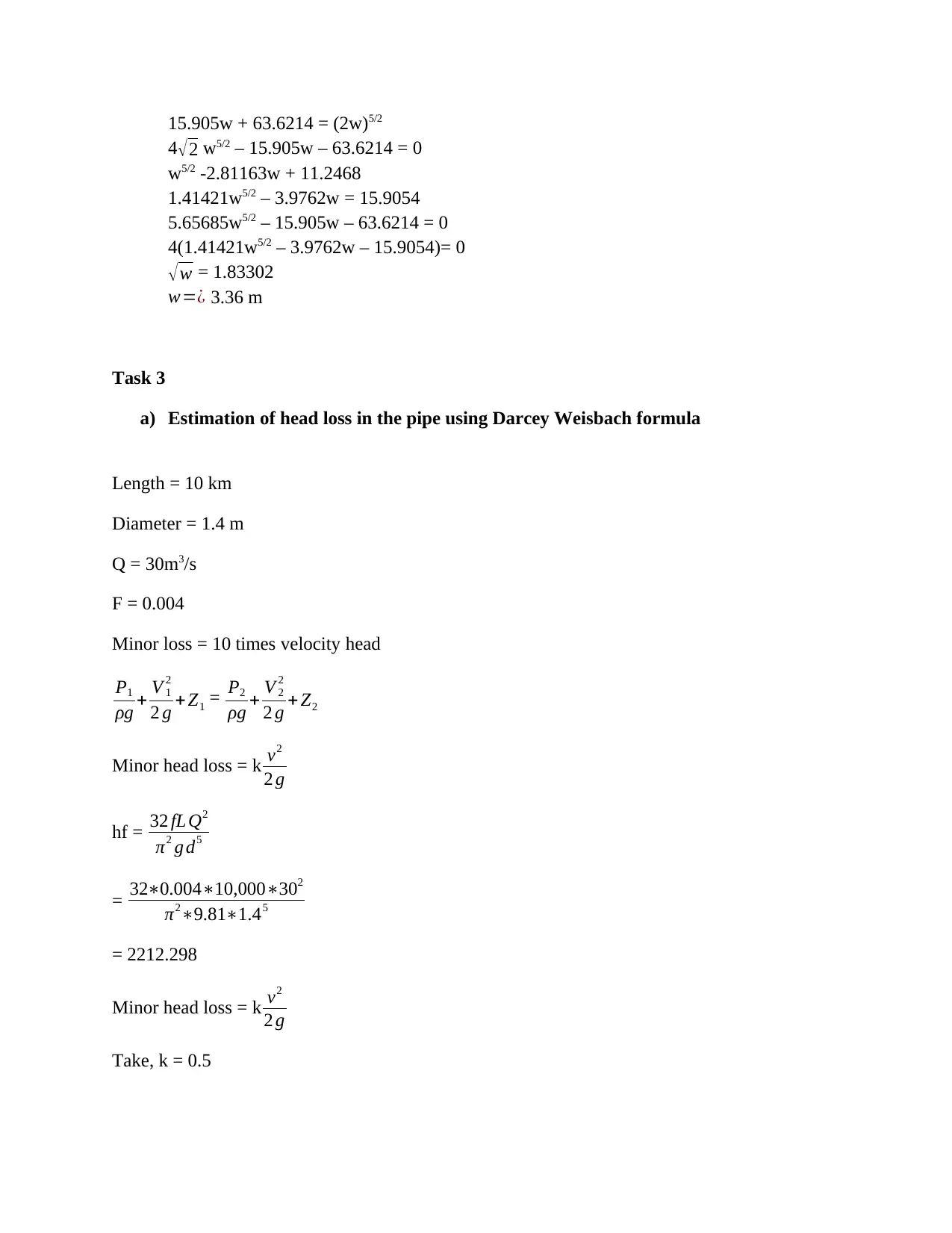
15.905w + 63.6214 = (2w)5/2
4√2 w5/2 – 15.905w – 63.6214 = 0
w5/2 -2.81163w + 11.2468
1.41421w5/2 – 3.9762w = 15.9054
5.65685w5/2 – 15.905w – 63.6214 = 0
4(1.41421w5/2 – 3.9762w – 15.9054)= 0
√ w = 1.83302
w=¿ 3.36 m
Task 3
a) Estimation of head loss in the pipe using Darcey Weisbach formula
Length = 10 km
Diameter = 1.4 m
Q = 30m3/s
F = 0.004
Minor loss = 10 times velocity head
P1
ρg + V 1
2
2 g + Z1 = P2
ρg + V 2
2
2 g + Z2
Minor head loss = k v2
2 g
hf = 32 fL Q2
π2 g d5
= 32∗0.004∗10,000∗302
π2∗9.81∗1.45
= 2212.298
Minor head loss = k v2
2 g
Take, k = 0.5
Paraphrase This Document
Need a fresh take? Get an instant paraphrase of this document with our AI Paraphraser
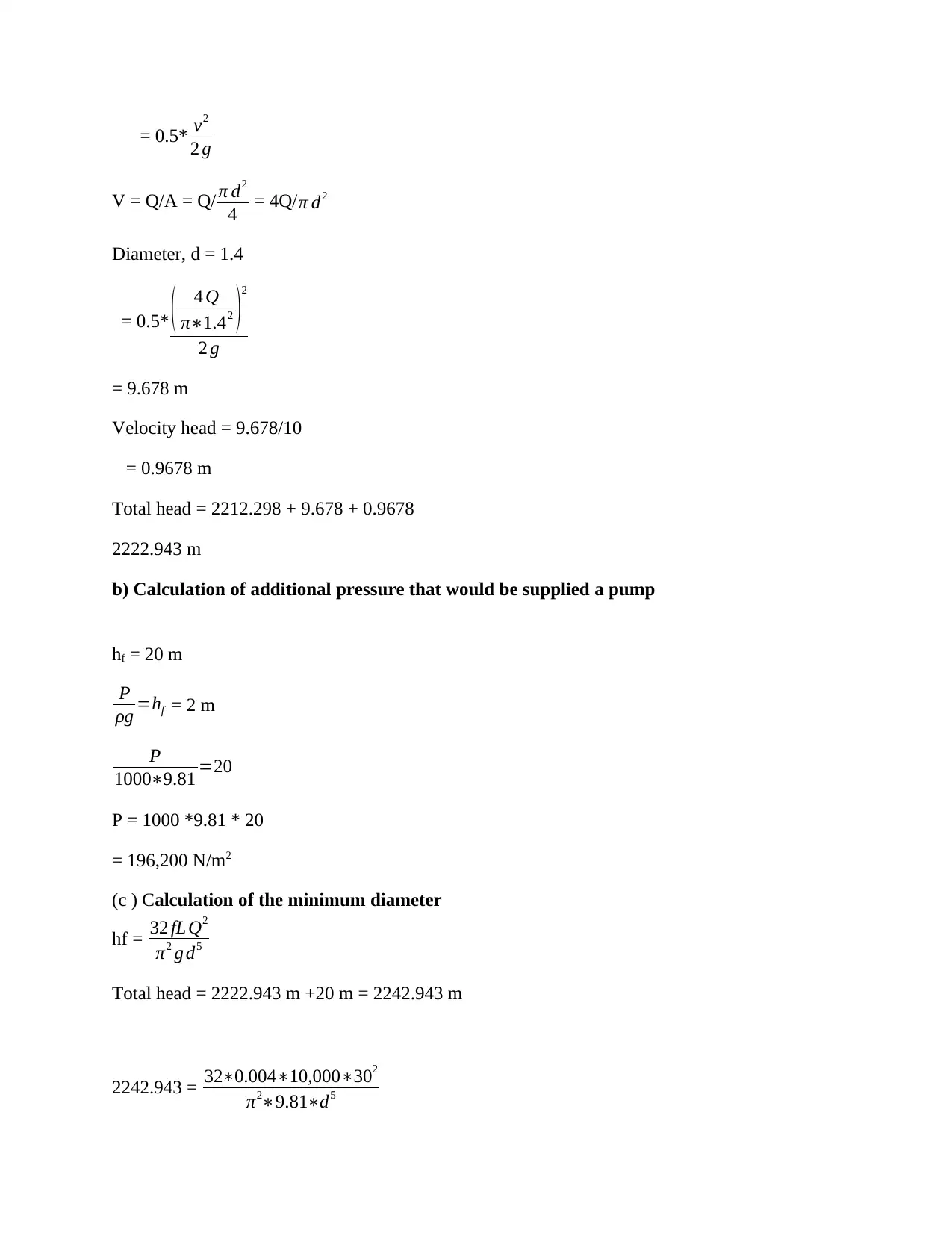
= 0.5* v2
2 g
V = Q/A = Q/ π d2
4 = 4Q/π d2
Diameter, d = 1.4
= 0.5* ( 4 Q
π∗1.42 )2
2 g
= 9.678 m
Velocity head = 9.678/10
= 0.9678 m
Total head = 2212.298 + 9.678 + 0.9678
2222.943 m
b) Calculation of additional pressure that would be supplied a pump
hf = 20 m
P
ρg =hf = 2 m
P
1000∗9.81 =20
P = 1000 *9.81 * 20
= 196,200 N/m2
(c ) Calculation of the minimum diameter
hf = 32 fL Q2
π2 g d5
Total head = 2222.943 m +20 m = 2242.943 m
2242.943 = 32∗0.004∗10,000∗302
π2∗9.81∗d5
2 g
V = Q/A = Q/ π d2
4 = 4Q/π d2
Diameter, d = 1.4
= 0.5* ( 4 Q
π∗1.42 )2
2 g
= 9.678 m
Velocity head = 9.678/10
= 0.9678 m
Total head = 2212.298 + 9.678 + 0.9678
2222.943 m
b) Calculation of additional pressure that would be supplied a pump
hf = 20 m
P
ρg =hf = 2 m
P
1000∗9.81 =20
P = 1000 *9.81 * 20
= 196,200 N/m2
(c ) Calculation of the minimum diameter
hf = 32 fL Q2
π2 g d5
Total head = 2222.943 m +20 m = 2242.943 m
2242.943 = 32∗0.004∗10,000∗302
π2∗9.81∗d5
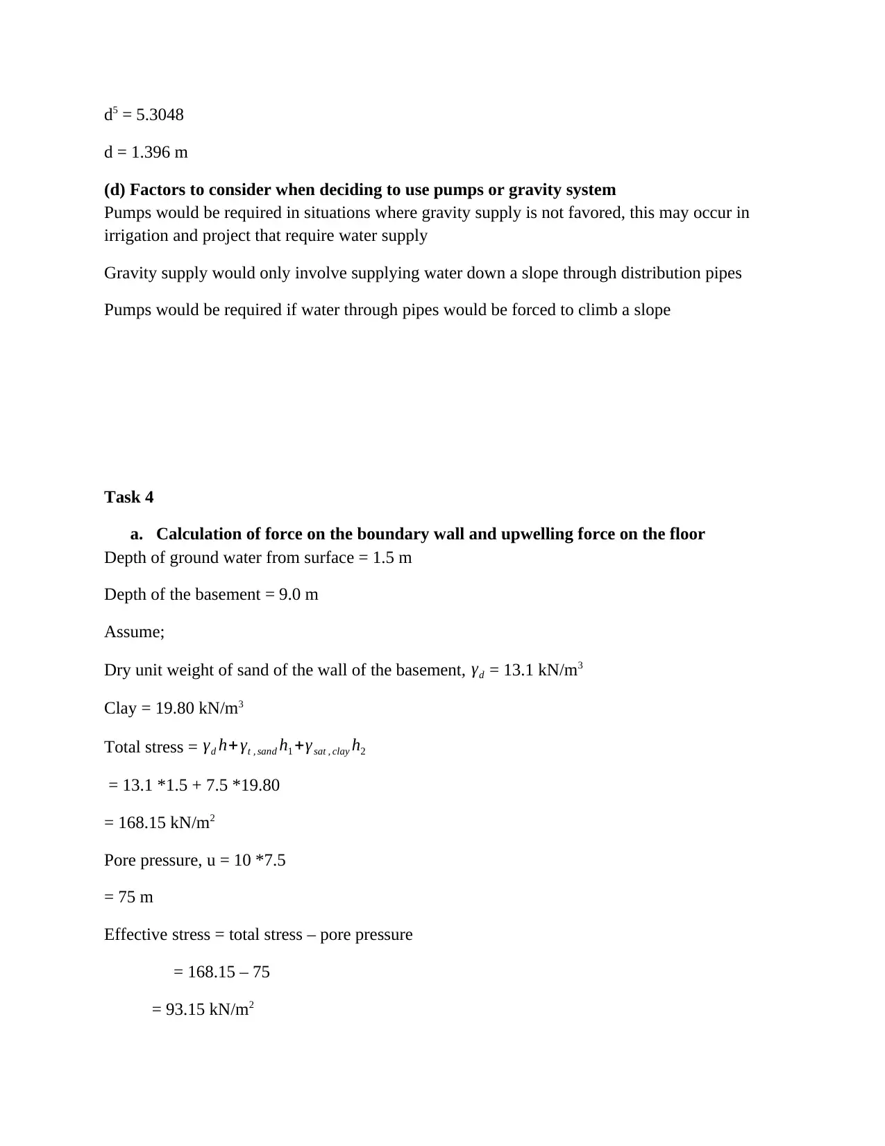
d5 = 5.3048
d = 1.396 m
(d) Factors to consider when deciding to use pumps or gravity system
Pumps would be required in situations where gravity supply is not favored, this may occur in
irrigation and project that require water supply
Gravity supply would only involve supplying water down a slope through distribution pipes
Pumps would be required if water through pipes would be forced to climb a slope
Task 4
a. Calculation of force on the boundary wall and upwelling force on the floor
Depth of ground water from surface = 1.5 m
Depth of the basement = 9.0 m
Assume;
Dry unit weight of sand of the wall of the basement, γd = 13.1 kN/m3
Clay = 19.80 kN/m3
Total stress = γd h+ γt , sand h1 +γsat , clay h2
= 13.1 *1.5 + 7.5 *19.80
= 168.15 kN/m2
Pore pressure, u = 10 *7.5
= 75 m
Effective stress = total stress – pore pressure
= 168.15 – 75
= 93.15 kN/m2
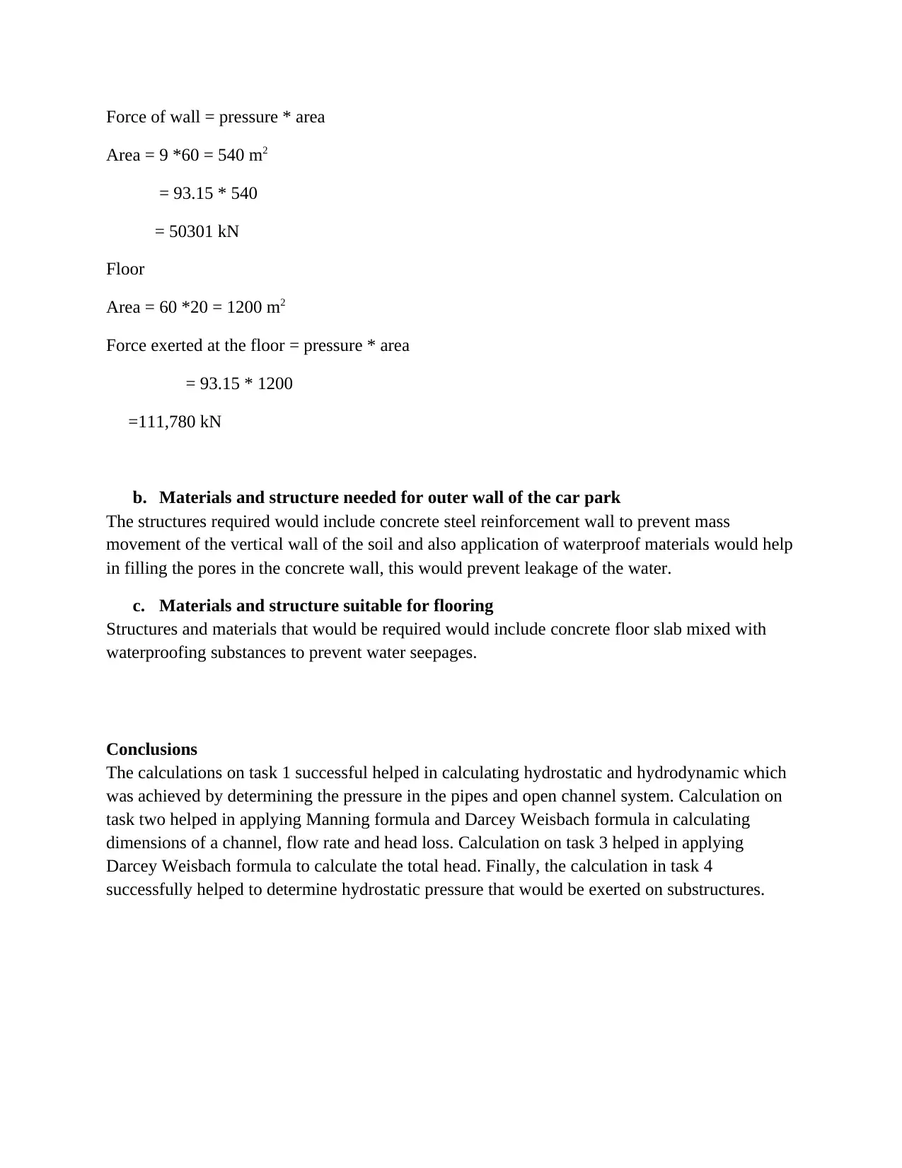
Force of wall = pressure * area
Area = 9 *60 = 540 m2
= 93.15 * 540
= 50301 kN
Floor
Area = 60 *20 = 1200 m2
Force exerted at the floor = pressure * area
= 93.15 * 1200
=111,780 kN
b. Materials and structure needed for outer wall of the car park
The structures required would include concrete steel reinforcement wall to prevent mass
movement of the vertical wall of the soil and also application of waterproof materials would help
in filling the pores in the concrete wall, this would prevent leakage of the water.
c. Materials and structure suitable for flooring
Structures and materials that would be required would include concrete floor slab mixed with
waterproofing substances to prevent water seepages.
Conclusions
The calculations on task 1 successful helped in calculating hydrostatic and hydrodynamic which
was achieved by determining the pressure in the pipes and open channel system. Calculation on
task two helped in applying Manning formula and Darcey Weisbach formula in calculating
dimensions of a channel, flow rate and head loss. Calculation on task 3 helped in applying
Darcey Weisbach formula to calculate the total head. Finally, the calculation in task 4
successfully helped to determine hydrostatic pressure that would be exerted on substructures.
Secure Best Marks with AI Grader
Need help grading? Try our AI Grader for instant feedback on your assignments.
References
Cheng, N.S. and Nguyen, H.T., 2011. Hydraulic radius for evaluating resistance induced by
simulated emergent vegetation in open-channel flows. Journal of hydraulic engineering, 137(9),
pp.995-1004.
Holmes, M.J., Parker, N.G. and Povey, M.J.W., 2011. Temperature dependence of bulk viscosity
in water using acoustic spectroscopy. In Journal of Physics: Conference Series (Vol. 269, No. 1,
p. 012011). IOP Publishing.
Kiijarvi, J., 2011. Darcy friction factor formulae in turbulent pipe flow. Lunowa Fluid Mechanics
Paper, 110727, pp.1-11.
Massey, B. S., Bernards and Ward-Smith. A. J., 2012. Mechanics of fluids. Spon Press, pp.298 - 358
Nejad, K.S., Berg, E.A. and Ringen, J.K., 2011, September. Effect of oil viscosity on water/oil
relative permeability. In International symposium of the society of core analysts, Austin, TX,
USA.
Niu, Z., Wang, R., Jiao, K., Du, Q. and Yin, Y., 2017. Direct numerical simulation of low
Reynolds number turbulent air-water transport in fuel cell flow channel. Science Bulletin, 62(1),
pp.31-39.
Niu, Z.,Örlü, R. and Schlatter, P., 2011. On the fluctuating wall-shear stress in zero pressure-
gradient turbulent boundary layer flows. Physics of fluids, 23(2), p.021704.
Song, S., Schmalz, B., Zhang, J.X., Li, G. and Fohrer, N., 2016. Application of modified
Manning formula in the determination of vertical profile velocity in natural rivers. Hydrology
Research, 48(1), pp.133-146.
Zhang, H.Q. and Sarica, C., 2011. Low liquid loading gas/liquid pipe flow. Journal of Natural
Gas Science and Engineering, 3(2), pp.413-422.

1 out of 12
Related Documents


Your All-in-One AI-Powered Toolkit for Academic Success.
+13062052269
info@desklib.com
Available 24*7 on WhatsApp / Email
![[object Object]](/_next/static/media/star-bottom.7253800d.svg)
Unlock your academic potential
© 2024 | Zucol Services PVT LTD | All rights reserved.