MECH202 Fluid Mechanics Lab: Bernoulli's Principle and Flow Analysis
VerifiedAdded on 2023/03/17
|6
|964
|53
Practical Assignment
AI Summary
This lab report analyzes Bernoulli's principle through an experiment using a Venturi meter. The experiment investigates the relationship between pressure and kinetic energy as dictated by Bernoulli's equation. The report includes calculations of inlet, throat, and outlet velocities for five different flow ...
HYDRAULIC GRADE LINES
1. Graph the hydraulic grade lines as given five flow rates. Tell the detail of types of energy
variation and effect. Show the different type of sections of the system.
Hydraulic Grade line (HGL), it is a sum of the hydraulic energy point below the total energy point
at a different section. Here we have different type of 5 run, with the help there are manometer
value given in the table below:
Run 1 Run 2 Run 3 Run 4 Run 5
Measuring bucket
Volume (L) 1 1 1 1 1
Discharge Time (sec)
27.26 15.3 9.27 6.53 5.13
27.14 16.4 10.74 6.62 5.1
27.86 15.5 10.7 7.09 6.17
Manometer A
(mm) 156 168 193 235 261
Manometer B
(mm) 155 160 173 195 207
Manometer C
(mm) 151 151 153 154 152
Manometer D
(mm) 146 143 132 110 94
Manometer E
(mm) 141 128 101 48 13
Manometer F
(mm) 145 142 130 115 110
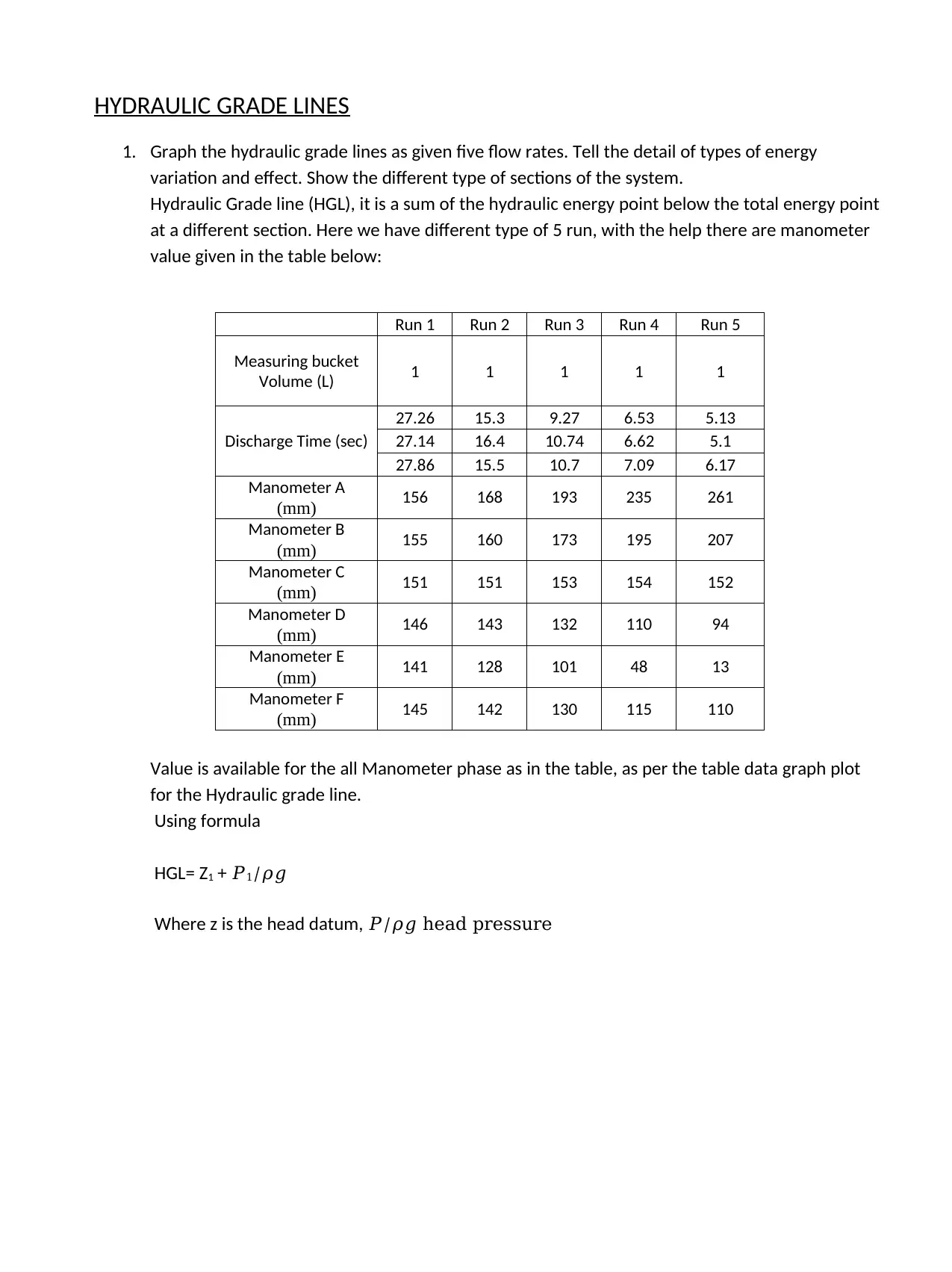
Value is available for the all Manometer phase as in the table, as per the table data graph plot
for the Hydraulic grade line.
Using formula
HGL= Z1 + 𝑃1/𝜌𝑔
Where z is the head datum, 𝑃/𝜌𝑔 head pressure
1. Graph the hydraulic grade lines as given five flow rates. Tell the detail of types of energy
variation and effect. Show the different type of sections of the system.
Hydraulic Grade line (HGL), it is a sum of the hydraulic energy point below the total energy point
at a different section. Here we have different type of 5 run, with the help there are manometer
value given in the table below:
Run 1 Run 2 Run 3 Run 4 Run 5
Measuring bucket
Volume (L) 1 1 1 1 1
Discharge Time (sec)
27.26 15.3 9.27 6.53 5.13
27.14 16.4 10.74 6.62 5.1
27.86 15.5 10.7 7.09 6.17
Manometer A
(mm) 156 168 193 235 261
Manometer B
(mm) 155 160 173 195 207
Manometer C
(mm) 151 151 153 154 152
Manometer D
(mm) 146 143 132 110 94
Manometer E
(mm) 141 128 101 48 13
Manometer F
(mm) 145 142 130 115 110
Value is available for the all Manometer phase as in the table, as per the table data graph plot
for the Hydraulic grade line.
Using formula
HGL= Z1 + 𝑃1/𝜌𝑔
Where z is the head datum, 𝑃/𝜌𝑔 head pressure
Paraphrase This Document
Need a fresh take? Get an instant paraphrase of this document with our AI Paraphraser
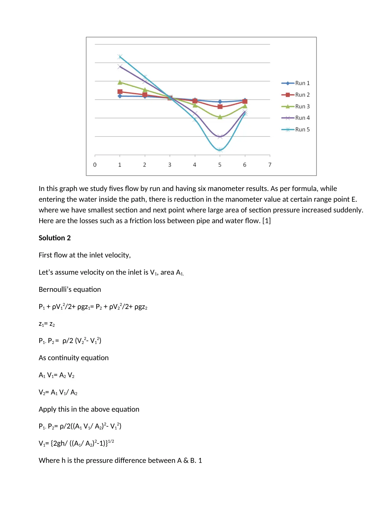
In this graph we study fives flow by run and having six manometer results. As per formula, while
entering the water inside the path, there is reduction in the manometer value at certain range point E.
where we have smallest section and next point where large area of section pressure increased suddenly.
Here are the losses such as a friction loss between pipe and water flow. [1]
Solution 2
First flow at the inlet velocity,
Let’s assume velocity on the inlet is V1, area A1,
Bernoulli’s equation
P1 + ρV12/2+ ρgz1= P2 + ρV22/2+ ρgz2
z1= z2
P1- P2 = ρ/2 (V22- V12)
As continuity equation
A1 V1= A2 V2
V2= A1 V1/ A2
Apply this in the above equation
P1- P2= ρ/2((A1 V1/ A2)2- V12)
V1= {2gh/ ((A1/ A2)2-1)}1/2
Where h is the pressure difference between A & B. 1
V1= {2*9.8*1/(( 25/ 13.9)4-1)}1/2
V1=1.44 m/s. Inlet Velocity
Similary for the throat velocity
V1= {2gh/(( A1/ A2)2-1)}1/2
Where h is 15
V1= {2*9.8*15/(( 10/ 25)4-1)}1/2
V1=17.41 m/s. throat Velocity
Similary for the outlet velocity
V1= {2gh/(( A1/ A2)2-1)}1/2
Where h is 4
V1= {2*9.8*4/(( 25/ 10)4-1)}1/2
V1=1.43 m/s. Outlet Velocity
For run 2
Inlet velocity 4.07m/s
Throat velocity 28.42m/s
Outlet velocity 2.68m/s
For run 3
Inlet velocity 6.43m/s
Throat velocity 43.11m/s
Outlet velocity 3.87m/s
For run 4
Inlet velocity 9.1m/s
Throat velocity 61.46m/s
Outlet velocity 5.87m/s
⊘ This is a preview!⊘
Do you want full access?
Subscribe today to unlock all pages.
Trusted by 1+ million students worldwide
Solution 3
Discharge rate
Qreal= CvQideal=
Cv(VtAt)=CvAt= CvAt(2g.p/pg+h)1/2/1-Dr/Dp4
For run 1 velocity 1.44m/s
Discharge rate 1/27.42= 3647 x 10-5
Qreal= CvQideal=Cv(VtAt)
Cv= Qreal/Qideal = (V*A)/ Qideal
=1.44*490.625 x 10-6/3647 x 10-5
=0.93
For run 2 velocity 4.07m/s
Discharge rate 1/15.73= 6350 x 10-5
Qreal= CvQideal=Cv(VtAt)
Cv= Qreal/Qideal = (V*A)/ Qideal
=4.07*490.625 x 10-6/6350 x 10-5
=0.83
For run 3 velocity 6.43m/s
Discharge rate 1/30.71= 3256 x 10-5
Qreal= CvQideal=Cv(VtAt)
Cv= Qreal/Qideal = (V*A)/ Qideal
=6.43*490.625 x 10-6/3256 x 10-5
=0.969
For run 4 velocity 9.1m/s
Discharge rate 1/20.24= 4940 x 10-5
Qreal= CvQideal=Cv(VtAt)
Cv= Qreal/Qideal = (V*A)/ Qideal
Paraphrase This Document
Need a fresh take? Get an instant paraphrase of this document with our AI Paraphraser
=9.1*490.625 x 10-6/4940 x 10-5=0.93
Here as per the calculation Cv we are getting value between 0.9 to 1.
Solution 4
Differences between the real flow rate (𝑄𝑟𝑒𝑎𝑙) and ideal flow rate (𝑄ideal)
Ideal flow has in viscid, incompressible, infinite bulk modulus, no head and no pressure loss
For real flow face head loss and friction effect, where the flow passes through the channel or pipe. With
Due to these losses fluid rate decreases with the increases the path. This is the practical example of
total energy line versus hydraulic grade line. [2]
Ideal flow, consider there is no loss of energy in flow. In other hand real flow count all type of losses
in the flow like head loss, friction loss etc. it can be defined by the plot of the Total energy line and
Hydraulic grade line.
Solution 5
Inside the channel and pipe where fluid flow, there is a head loss occur it should be counted, Effect of
this show the flow rate of the fluid and velocity.
Solution 6
Main important application of the equation of Bernoulli’s is Pitot tube. It is used in aircraft to calculate
the speed with the help of air flow. Spinning of balls (Magnus effect), aircraft lift, Venturimeter & efflux
speed. [2]
Reference:
[1] R. Rajput, Fluid Mechanics and Hydraulic Machines, S. Chand publication, 2016
[2] M. Raisinghania, Fluid Dynamics, S. Chand publication, 2009
[1] R. Rajput, Fluid Mechanics and Hydraulic Machines, S. Chand publication, 2016
[2] M. Raisinghania, Fluid Dynamics, S. Chand publication, 2009
⊘ This is a preview!⊘
Do you want full access?
Subscribe today to unlock all pages.
Trusted by 1+ million students worldwide
1 out of 6
Your All-in-One AI-Powered Toolkit for Academic Success.
+13062052269
info@desklib.com
Available 24*7 on WhatsApp / Email
![[object Object]](/_next/static/media/star-bottom.7253800d.svg)
Unlock your academic potential
© 2024 | Zucol Services PVT LTD | All rights reserved.