Advanced Pneumatic and Hydraulic Systems Design - TU Engineering
VerifiedAdded on 2023/06/11
|20
|2101
|384
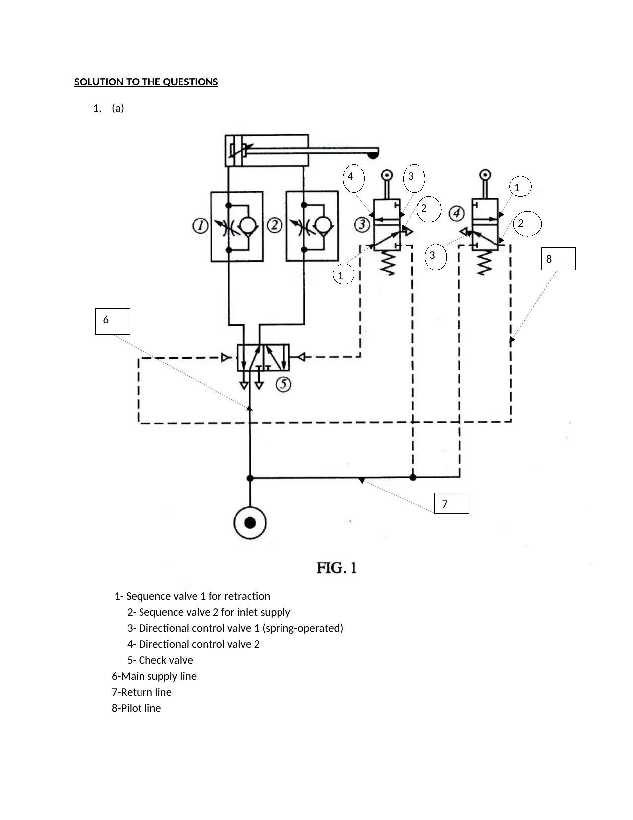
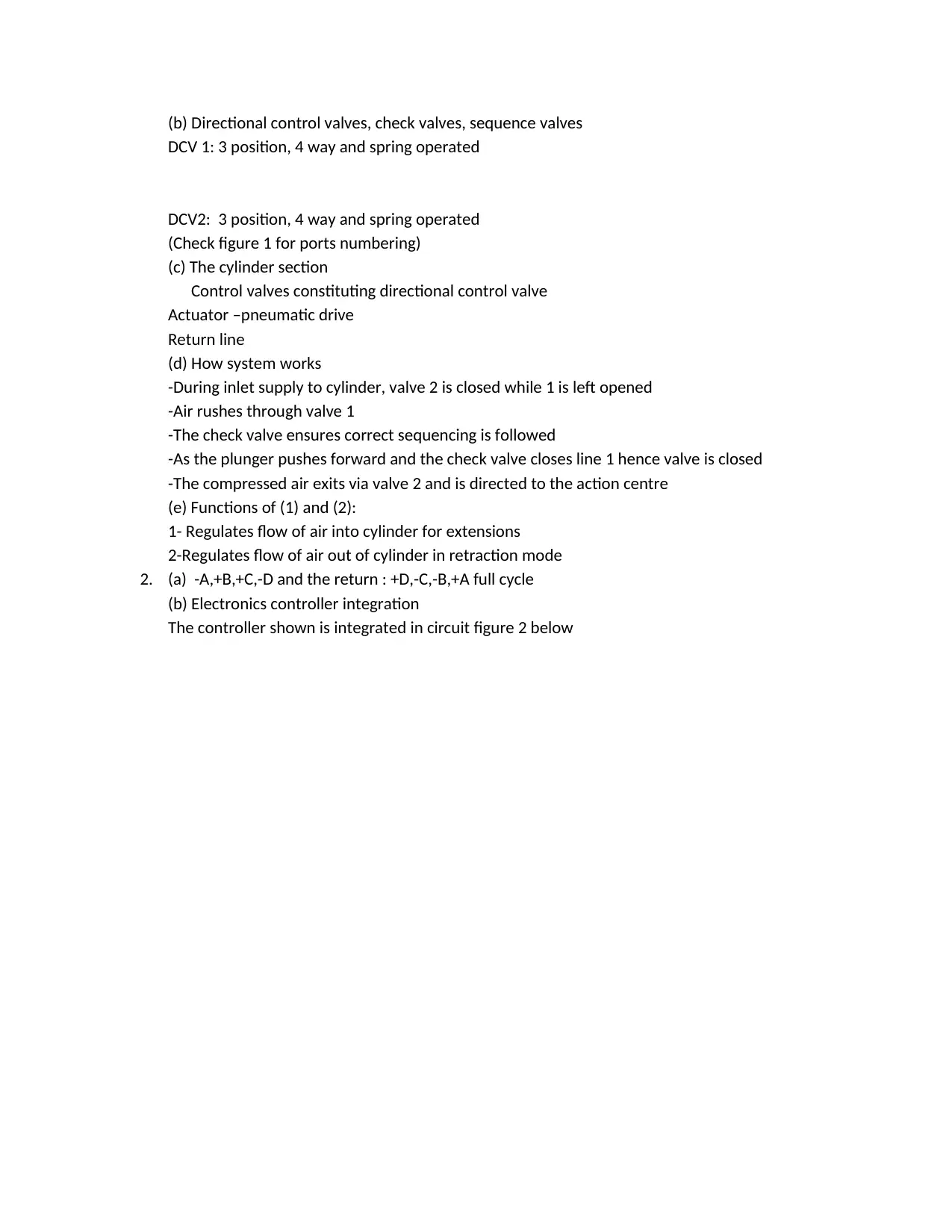
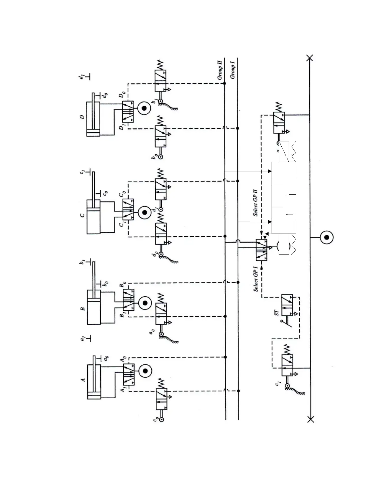
Practical Assignment
AI Summary
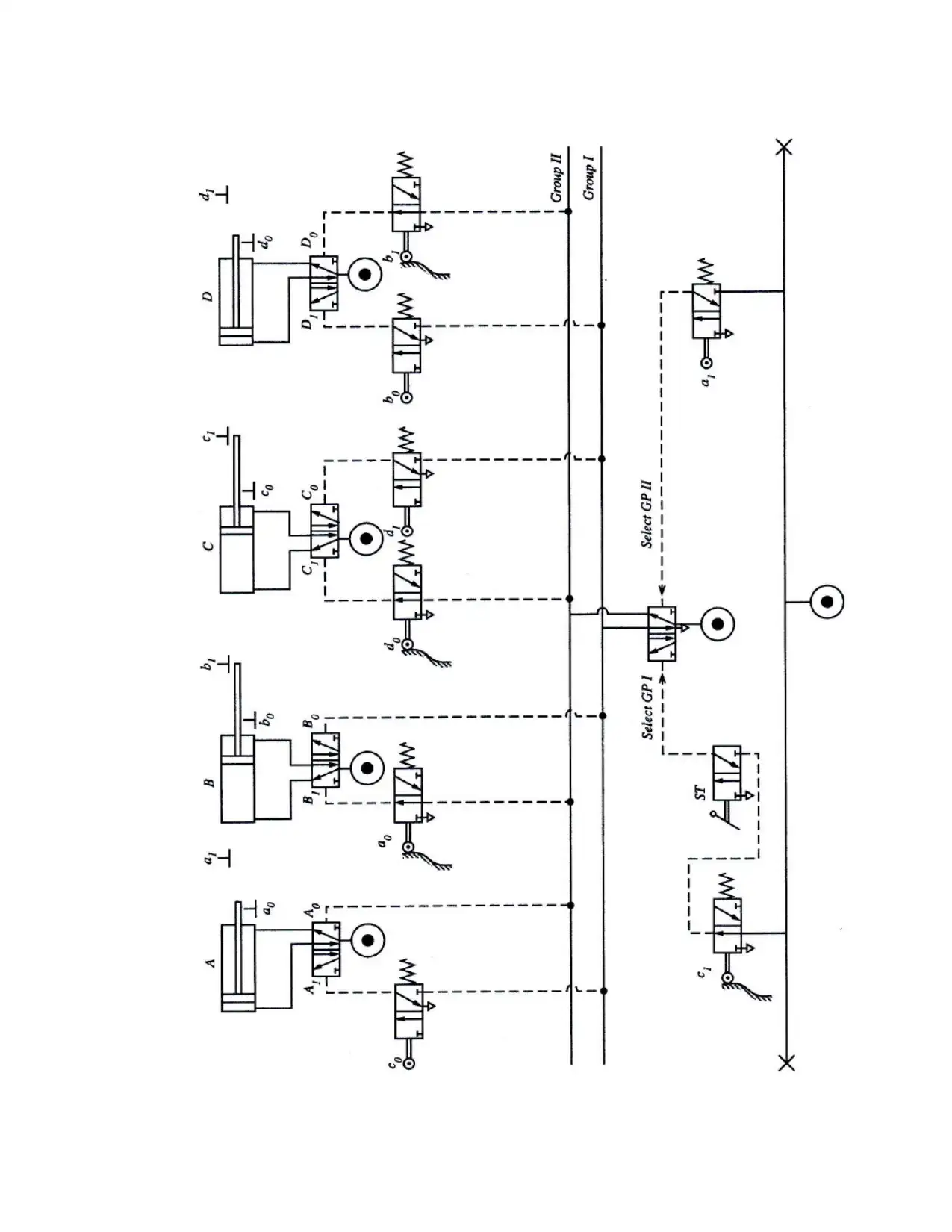
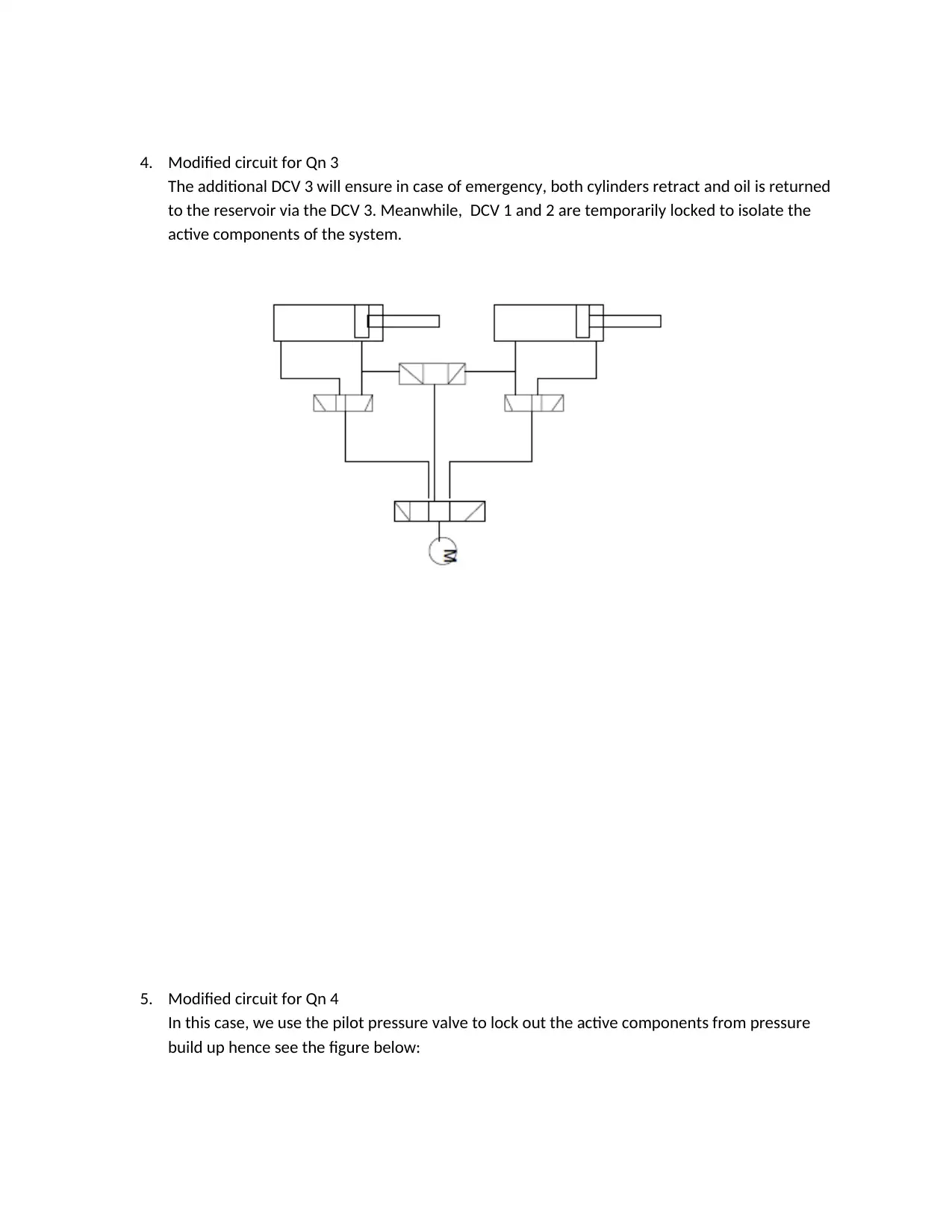
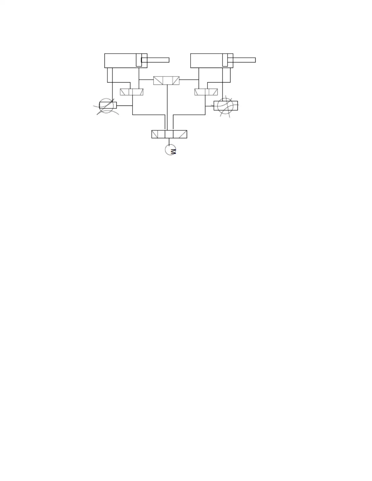
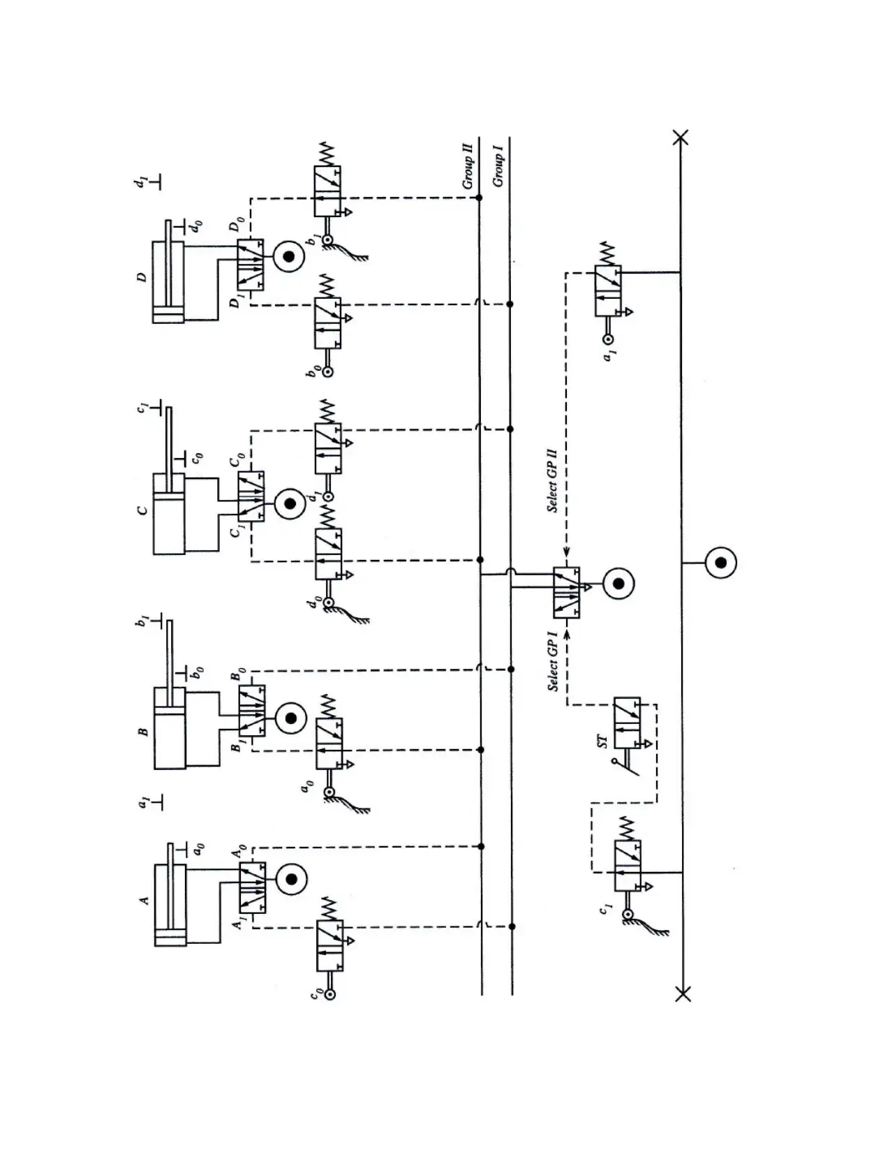
This assignment provides detailed solutions to problems related to pneumatic and hydraulic systems, covering topics such as circuit design, component analysis, and system operation. It includes explanations of pneumatic circuit diagrams with directional control valves, check valves, and sequence valves. The assignment also addresses hydraulic circuits using cascade systems, modifications for emergency retraction, and the integration of electronic controllers. Further, it delves into rotary actuators, multistage compressors, and the operational principles of rotary vane compressors. Calculations for system pressure and flow rates are provided, along with discussions on variable displacement axial piston pumps and positive displacement compressors. The document also covers air drying methods, material selection for distribution mains, and lubrication techniques. The assignment concludes with troubleshooting tips for overheating compressors, a system monitoring chart, and precautions for changing hydraulic fluids. This resource is contributed by a student and is available on Desklib, where students can find a wide range of study tools and solved assignments.

1 out of 20
Related Documents


Your All-in-One AI-Powered Toolkit for Academic Success.
+13062052269
info@desklib.com
Available 24*7 on WhatsApp / Email
![[object Object]](/_next/static/media/star-bottom.7253800d.svg)
Copyright © 2020–2026 A2Z Services. All Rights Reserved. Developed and managed by ZUCOL.