Simscape Fluids Project: Hydraulic Press Design and Analysis
VerifiedAdded on 2023/06/14
|27
|3595
|179
Project
AI Summary
This project report presents the design and analysis of a hydraulic press using Simscape Fluids. It begins with an introduction to hydraulic systems and their applications, followed by a literature review of relevant studies. The report then elaborates on the working principle of a hydraulic press, detailing its components such as hydraulic fluids, double-acting cylinders, and pressure relief valves. A case study is developed, and a comparative analysis is performed between a conventional press and a modified proposed press, examining characteristics like piston velocity, position, and flow rates. The report also addresses health and safety practices, including pipe analysis and other safety features. Finally, it discusses the results, compares them graphically, and provides conclusions and recommendations for optimizing hydraulic press design and reducing fluid power wastage.
Contents
List of Figures.............................................................................................................................................2
Chapter 1.....................................................................................................................................................3
Introduction.............................................................................................................................................3
Chapter 2.....................................................................................................................................................4
Literature review.....................................................................................................................................4
Chapter 3.....................................................................................................................................................6
Working principle of Hydraulic press......................................................................................................6
Principles of hydraulics.......................................................................................................................6
Hydraulic System................................................................................................................................6
Working of Hydraulic Press................................................................................................................6
Components of Hydraulic Press:.........................................................................................................6
Hydraulic Fluid................................................................................................................................6
Double acting cylinder.....................................................................................................................6
Pressure relief valve:........................................................................................................................7
Chapter 4.....................................................................................................................................................8
Development of case study......................................................................................................................8
Chapter 5.....................................................................................................................................................9
Analysis and comparison of characteristic features of presses.................................................................9
Conventional Press..............................................................................................................................9
Modified Proposed Press...................................................................................................................16
Chapter 6...................................................................................................................................................22
Comparison of results and graph plotting in excel.................................................................................22
Chapter 7...................................................................................................................................................24
Health and safety practices....................................................................................................................24
Safety check of pipes.........................................................................................................................24
Thin pipe analysis..............................................................................................................................24
Other safety feature of proposed design.............................................................................................24
Chapter 6...................................................................................................................................................26
Result and Discussions..........................................................................................................................26
References...............................................................................................................................................27
Paraphrase This Document
Need a fresh take? Get an instant paraphrase of this document with our AI Paraphraser
List of Figures
Figure 1 Double acting Hydraulic cylinder.....................................................................................6
Figure 2 Pressure relief valve..........................................................................................................7
Figure 3 Hydraulic circuit of Hydraulic press.................................................................................8
Figure 4 Input to 4-way valve through actuator..............................................................................9
Figure 5 Rod velocity in conventional press.................................................................................10
Figure 6 Rod position in Convention press...................................................................................11
Figure 7 Flow delivered by pump in conventional press...............................................................12
Figure 8 Flow through relief valve in conventional press.............................................................13
Figure 9 Hydraulic circuit of Proposed Hydraulic Press...............................................................14
Figure 10 Rod velocity in Proposed Press.....................................................................................15
Figure 11 Rod Position in Proposed Press.....................................................................................16
Figure 12 Flow delivered by pump in proposed press...................................................................17
Figure 13 Flow going through relief valve in proposed design. Amount of fluid wasted through
relief valve is almost 2.5 times less...............................................................................................18
Chapter 1
Introduction
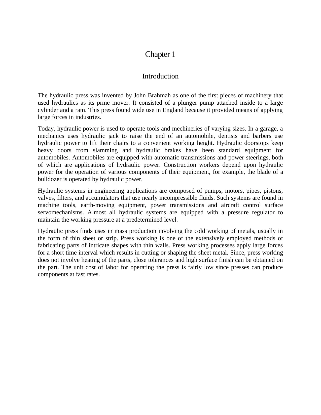
The hydraulic press was invented by John Brahmah as one of the first pieces of machinery that
used hydraulics as its prme mover. It consisted of a plunger pump attached inside to a large
cylinder and a ram. This press found wide use in England because it provided means of applying
large forces in industries.
Today, hydraulic power is used to operate tools and mechineries of varying sizes. In a garage, a
mechanics uses hydraulic jack to raise the end of an automobile, dentists and barbers use
hydraulic power to lift their chairs to a convenient working height. Hydraulic doorstops keep
heavy doors from slamming and hydraulic brakes have been standard equipment for
automobiles. Automobiles are equipped with automatic transmissions and power steerings, both
of which are applications of hydraulic power. Construction workers depend upon hydraulic
power for the operation of various components of their equipment, for example, the blade of a
bulldozer is operated by hydraulic power.
Hydraulic systems in engineering applications are composed of pumps, motors, pipes, pistons,
valves, filters, and accumulators that use nearly incompressible fluids. Such systems are found in
machine tools, earth-moving equipment, power transmissions and aircraft control surface
servomechanisms. Almost all hydraulic systems are equipped with a pressure regulator to
maintain the working pressure at a predetermined level.
Hydraulic press finds uses in mass production involving the cold working of metals, usually in
the form of thin sheet or strip. Press working is one of the extensively employed methods of
fabricating parts of intricate shapes with thin walls. Press working processes apply large forces
for a short time interval which results in cutting or shaping the sheet metal. Since, press working
does not involve heating of the parts, close tolerances and high surface finish can be obtained on
the part. The unit cost of labor for operating the press is fairly low since presses can produce
components at fast rates.
Introduction
The hydraulic press was invented by John Brahmah as one of the first pieces of machinery that
used hydraulics as its prme mover. It consisted of a plunger pump attached inside to a large
cylinder and a ram. This press found wide use in England because it provided means of applying
large forces in industries.
Today, hydraulic power is used to operate tools and mechineries of varying sizes. In a garage, a
mechanics uses hydraulic jack to raise the end of an automobile, dentists and barbers use
hydraulic power to lift their chairs to a convenient working height. Hydraulic doorstops keep
heavy doors from slamming and hydraulic brakes have been standard equipment for
automobiles. Automobiles are equipped with automatic transmissions and power steerings, both
of which are applications of hydraulic power. Construction workers depend upon hydraulic
power for the operation of various components of their equipment, for example, the blade of a
bulldozer is operated by hydraulic power.
Hydraulic systems in engineering applications are composed of pumps, motors, pipes, pistons,
valves, filters, and accumulators that use nearly incompressible fluids. Such systems are found in
machine tools, earth-moving equipment, power transmissions and aircraft control surface
servomechanisms. Almost all hydraulic systems are equipped with a pressure regulator to
maintain the working pressure at a predetermined level.
Hydraulic press finds uses in mass production involving the cold working of metals, usually in
the form of thin sheet or strip. Press working is one of the extensively employed methods of
fabricating parts of intricate shapes with thin walls. Press working processes apply large forces
for a short time interval which results in cutting or shaping the sheet metal. Since, press working
does not involve heating of the parts, close tolerances and high surface finish can be obtained on
the part. The unit cost of labor for operating the press is fairly low since presses can produce
components at fast rates.
⊘ This is a preview!⊘
Do you want full access?
Subscribe today to unlock all pages.
Trusted by 1+ million students worldwide
Chapter 2
Literature review
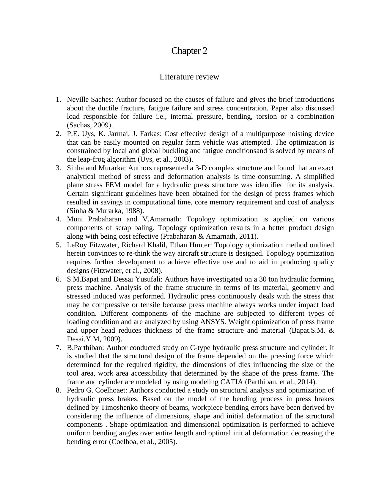
1. Neville Saches: Author focused on the causes of failure and gives the brief introductions
about the ductile fracture, fatigue failure and stress concentration. Paper also discussed
load responsible for failure i.e., internal pressure, bending, torsion or a combination
(Sachas, 2009).
2. P.E. Uys, K. Jarmai, J. Farkas: Cost effective design of a multipurpose hoisting device
that can be easily mounted on regular farm vehicle was attempted. The optimization is
constrained by local and global buckling and fatigue conditionsand is solved by means of
the leap-frog algorithm (Uys, et al., 2003).
3. Sinha and Murarka: Authors represented a 3-D complex structure and found that an exact
analytical method of stress and deformation analysis is time-consuming. A simplified
plane stress FEM model for a hydraulic press structure was identified for its analysis.
Certain significant guidelines have been obtained for the design of press frames which
resulted in savings in computational time, core memory requirement and cost of analysis
(Sinha & Murarka, 1988).
4. Muni Prabaharan and V.Amarnath: Topology optimization is applied on various
components of scrap baling. Topology optimization results in a better product design
along with being cost effective (Prabaharan & Amarnath, 2011).
5. LeRoy Fitzwater, Richard Khalil, Ethan Hunter: Topology optimization method outlined
herein convinces to re-think the way aircraft structure is designed. Topology optimization
requires further development to achieve effective use and to aid in producing quality
designs (Fitzwater, et al., 2008).
6. S.M.Bapat and Dessai Yusufali: Authors have investigated on a 30 ton hydraulic forming
press machine. Analysis of the frame structure in terms of its material, geometry and
stressed induced was performed. Hydraulic press continuously deals with the stress that
may be compressive or tensile because press machine always works under impact load
condition. Different components of the machine are subjected to different types of
loading condition and are analyzed by using ANSYS. Weight optimization of press frame
and upper head reduces thickness of the frame structure and material (Bapat.S.M. &
Desai.Y.M, 2009).
7. B.Parthiban: Author conducted study on C-type hydraulic press structure and cylinder. It
is studied that the structural design of the frame depended on the pressing force which
determined for the required rigidity, the dimensions of dies influencing the size of the
tool area, work area accessibility that determined by the shape of the press frame. The
frame and cylinder are modeled by using modeling CATIA (Parthiban, et al., 2014).
8. Pedro G. Coelhoaet: Authors conducted a study on structural analysis and optimization of
hydraulic press brakes. Based on the model of the bending process in press brakes
defined by Timoshenko theory of beams, workpiece bending errors have been derived by
considering the influence of dimensions, shape and initial deformation of the structural
components . Shape optimization and dimensional optimization is performed to achieve
uniform bending angles over entire length and optimal initial deformation decreasing the
bending error (Coelhoa, et al., 2005).
Literature review
1. Neville Saches: Author focused on the causes of failure and gives the brief introductions
about the ductile fracture, fatigue failure and stress concentration. Paper also discussed
load responsible for failure i.e., internal pressure, bending, torsion or a combination
(Sachas, 2009).
2. P.E. Uys, K. Jarmai, J. Farkas: Cost effective design of a multipurpose hoisting device
that can be easily mounted on regular farm vehicle was attempted. The optimization is
constrained by local and global buckling and fatigue conditionsand is solved by means of
the leap-frog algorithm (Uys, et al., 2003).
3. Sinha and Murarka: Authors represented a 3-D complex structure and found that an exact
analytical method of stress and deformation analysis is time-consuming. A simplified
plane stress FEM model for a hydraulic press structure was identified for its analysis.
Certain significant guidelines have been obtained for the design of press frames which
resulted in savings in computational time, core memory requirement and cost of analysis
(Sinha & Murarka, 1988).
4. Muni Prabaharan and V.Amarnath: Topology optimization is applied on various
components of scrap baling. Topology optimization results in a better product design
along with being cost effective (Prabaharan & Amarnath, 2011).
5. LeRoy Fitzwater, Richard Khalil, Ethan Hunter: Topology optimization method outlined
herein convinces to re-think the way aircraft structure is designed. Topology optimization
requires further development to achieve effective use and to aid in producing quality
designs (Fitzwater, et al., 2008).
6. S.M.Bapat and Dessai Yusufali: Authors have investigated on a 30 ton hydraulic forming
press machine. Analysis of the frame structure in terms of its material, geometry and
stressed induced was performed. Hydraulic press continuously deals with the stress that
may be compressive or tensile because press machine always works under impact load
condition. Different components of the machine are subjected to different types of
loading condition and are analyzed by using ANSYS. Weight optimization of press frame
and upper head reduces thickness of the frame structure and material (Bapat.S.M. &
Desai.Y.M, 2009).
7. B.Parthiban: Author conducted study on C-type hydraulic press structure and cylinder. It
is studied that the structural design of the frame depended on the pressing force which
determined for the required rigidity, the dimensions of dies influencing the size of the
tool area, work area accessibility that determined by the shape of the press frame. The
frame and cylinder are modeled by using modeling CATIA (Parthiban, et al., 2014).
8. Pedro G. Coelhoaet: Authors conducted a study on structural analysis and optimization of
hydraulic press brakes. Based on the model of the bending process in press brakes
defined by Timoshenko theory of beams, workpiece bending errors have been derived by
considering the influence of dimensions, shape and initial deformation of the structural
components . Shape optimization and dimensional optimization is performed to achieve
uniform bending angles over entire length and optimal initial deformation decreasing the
bending error (Coelhoa, et al., 2005).
Paraphrase This Document
Need a fresh take? Get an instant paraphrase of this document with our AI Paraphraser

9. H.N.Chauhan and M.P.Bambhania: Authors shows that, FE Analysis has been applied on
a frame of 63 ton power press machine.. It is said that Instead of sharp corner of the c -
frame, fillet is provided to reduce failure in the structure. Amount of fillet depends on
load condition experienced by frame and it is analyzed by using FEM Tool. It is
concluded that simulation software is the powerful tool for prediction of plate required
for a given load. This analysis given the result of reduction in thickness of plate of frame
structure, material saving and as well as cost benefits (H.N.Chauhan & M.P.Bambhania,
2013).
Chapter 3
Working principle of Hydraulic press
Principles of hydraulics: Hydraulics is the science of transmitting force and/or motion through
the medium of a confined liquid and is based on Pascal’s law. In a hydraulic device, power is
transmitted by pushing on a confined liquid. The transfer of energy takes place because a
quantity of liquid is subject to pressure.
Hydraulic System: A hydraulic system confines a liquid in such a way that it uses the Pascal’s
law to transmit power and do work. The oil reservoir serves as a storehouse and filters, strainers,
and magnetic plugs removes harmful impurities that clog passages and damage parts. Heat
exchanges are used to keep the oil temperature within safe limits and prevent deterioration of the
oil.
Working of Hydraulic Press: Since the hydraulic press works on the basis of Pascal's Law, its
working is similar to the one of the hydraulic system. A hydraulic press consists of cylinders,
pistons, pressure relief valves, hydraulic pipes etc. The system comprises of two cylinders; the
fluid is poured in the cylinder having a small diameter. The piston in this cylinder is pushed to
compresses the fluid in it and flows through a pipe into the larger cylinder. The pressure is
exerted on the larger cylinder and the piston in cylinder. The force applied on the fluids by the
smaller cylinder results in a larger force in the larger cylinder. Hydraulic presses are used in
industries where a large pressure is required for compressing metals into sheets.
Components of Hydraulic Press:
Hydraulic Fluid The hydraulic fluid has four primary purposes: (1) To transmit power, (2) To
lubricate moving parts, (3) To seal clearance between parts, and (4) To cool or dissipate heat
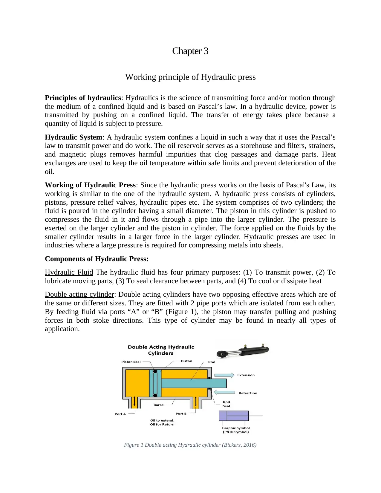
Double acting cylinder: Double acting cylinders have two opposing effective areas which are of
the same or different sizes. They are fitted with 2 pipe ports which are isolated from each other.
By feeding fluid via ports “A” or “B” (Figure 1), the piston may transfer pulling and pushing
forces in both stoke directions. This type of cylinder may be found in nearly all types of
application.
Figure 1 Double acting Hydraulic cylinder (Bickers, 2016)
Working principle of Hydraulic press
Principles of hydraulics: Hydraulics is the science of transmitting force and/or motion through
the medium of a confined liquid and is based on Pascal’s law. In a hydraulic device, power is
transmitted by pushing on a confined liquid. The transfer of energy takes place because a
quantity of liquid is subject to pressure.
Hydraulic System: A hydraulic system confines a liquid in such a way that it uses the Pascal’s
law to transmit power and do work. The oil reservoir serves as a storehouse and filters, strainers,
and magnetic plugs removes harmful impurities that clog passages and damage parts. Heat
exchanges are used to keep the oil temperature within safe limits and prevent deterioration of the
oil.
Working of Hydraulic Press: Since the hydraulic press works on the basis of Pascal's Law, its
working is similar to the one of the hydraulic system. A hydraulic press consists of cylinders,
pistons, pressure relief valves, hydraulic pipes etc. The system comprises of two cylinders; the
fluid is poured in the cylinder having a small diameter. The piston in this cylinder is pushed to
compresses the fluid in it and flows through a pipe into the larger cylinder. The pressure is
exerted on the larger cylinder and the piston in cylinder. The force applied on the fluids by the
smaller cylinder results in a larger force in the larger cylinder. Hydraulic presses are used in
industries where a large pressure is required for compressing metals into sheets.
Components of Hydraulic Press:
Hydraulic Fluid The hydraulic fluid has four primary purposes: (1) To transmit power, (2) To
lubricate moving parts, (3) To seal clearance between parts, and (4) To cool or dissipate heat
Double acting cylinder: Double acting cylinders have two opposing effective areas which are of
the same or different sizes. They are fitted with 2 pipe ports which are isolated from each other.
By feeding fluid via ports “A” or “B” (Figure 1), the piston may transfer pulling and pushing
forces in both stoke directions. This type of cylinder may be found in nearly all types of
application.
Figure 1 Double acting Hydraulic cylinder (Bickers, 2016)
⊘ This is a preview!⊘
Do you want full access?
Subscribe today to unlock all pages.
Trusted by 1+ million students worldwide
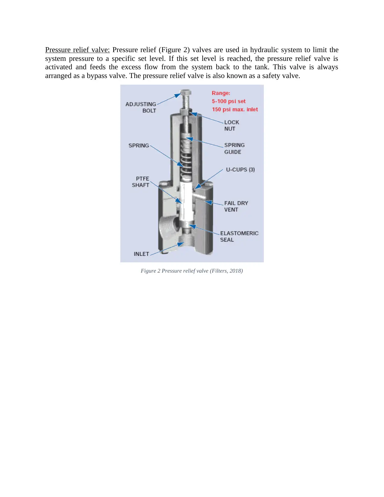
Pressure relief valve: Pressure relief (Figure 2) valves are used in hydraulic system to limit the
system pressure to a specific set level. If this set level is reached, the pressure relief valve is
activated and feeds the excess flow from the system back to the tank. This valve is always
arranged as a bypass valve. The pressure relief valve is also known as a safety valve.
Figure 2 Pressure relief valve (Filters, 2018)
Paraphrase This Document
Need a fresh take? Get an instant paraphrase of this document with our AI Paraphraser
Chapter 4
Development of case study
This study is aimed to design a hydraulic press in Simulink using hydraulic blocks and analyze
various systems characteristics like piston position, piston velocity, flow rate delivered by pump
and fluid power wasted through relief valve when the press is bottomed out.
It is assumed that press simulated here develops a maximum pressure of 95e5 Pa inside
cylinders. The fluid is delivered through a fixed displacement pump with nominal pressure of
100e5 Pa and relief valve is set at 95e5 +/- 5e5 Pa. Power source for pump is a constant angular
velocity motor running at 188 rpm. A 4-way valve is used to connect cylinders with the pump.
The motion of 4-way valve is controlled through a servo-valve actuator whose input is shown in
Figure 5. The valve is gradually opened till 2 secs and is held at full open for a total of 3 secs and
is then gradually returned to partial opening in reverse direction to enable piston to reach the
initial position.
The whole system is simulated for a total of 10 secs and various parameters are analyzed as
shown in proceeding sections.
Based on the waste fluid that flows through relief valve as shown in Figure 9, it is concluded that
fluid power is wasted when the press is required to hold the bottomed-out configuration for an
extended period of time. To optimize the press and reduce the wastage of fluid power, following
modifications are proposed:
1. Replacement of fixed displacement pump with a variable displacement, pressure
compensated pump.
2. Installation of closed feedback and control system to drive the servo-actuator.
It is assumed that efficiency of motor driving the pump is not of concern. The volumetric
efficiency of pump is 0.92 and overall efficiency is 0.8. The internal diameter of pipes is 0.02m
and each segment of pipe is 3m in length with internal roughness height of 1.5e-5m. The
resistance to fluid flow offered by flow rate sensors is negligible. Connection of piston rod with
translational sensor is ideal. The mass that piston rod acts against in both cases is same and equal
to 100kg with translational spring constant of 15000N/m and damping constant of 2N/(m/s). The
gain of servo-actuator is also kept at 50 in both cases.
The following chapter gives a comparison of various characteristics obtained from analysis of
conventional and modified hydraulic press.
Chapter 5
Analysis and comparison of characteristic features of presses
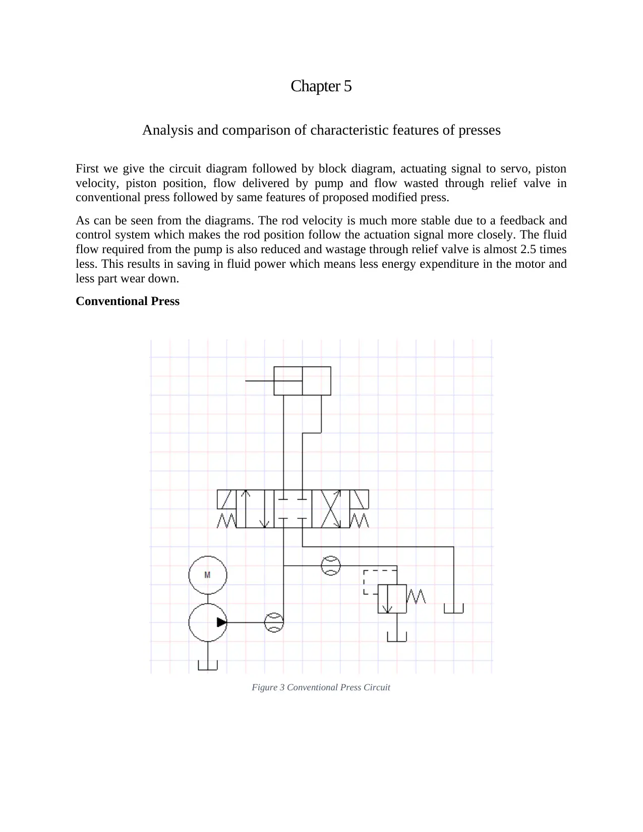
First we give the circuit diagram followed by block diagram, actuating signal to servo, piston
velocity, piston position, flow delivered by pump and flow wasted through relief valve in
conventional press followed by same features of proposed modified press.
As can be seen from the diagrams. The rod velocity is much more stable due to a feedback and
control system which makes the rod position follow the actuation signal more closely. The fluid
flow required from the pump is also reduced and wastage through relief valve is almost 2.5 times
less. This results in saving in fluid power which means less energy expenditure in the motor and
less part wear down.
Conventional Press
Figure 3 Conventional Press Circuit
Analysis and comparison of characteristic features of presses
First we give the circuit diagram followed by block diagram, actuating signal to servo, piston
velocity, piston position, flow delivered by pump and flow wasted through relief valve in
conventional press followed by same features of proposed modified press.
As can be seen from the diagrams. The rod velocity is much more stable due to a feedback and
control system which makes the rod position follow the actuation signal more closely. The fluid
flow required from the pump is also reduced and wastage through relief valve is almost 2.5 times
less. This results in saving in fluid power which means less energy expenditure in the motor and
less part wear down.
Conventional Press
Figure 3 Conventional Press Circuit
⊘ This is a preview!⊘
Do you want full access?
Subscribe today to unlock all pages.
Trusted by 1+ million students worldwide
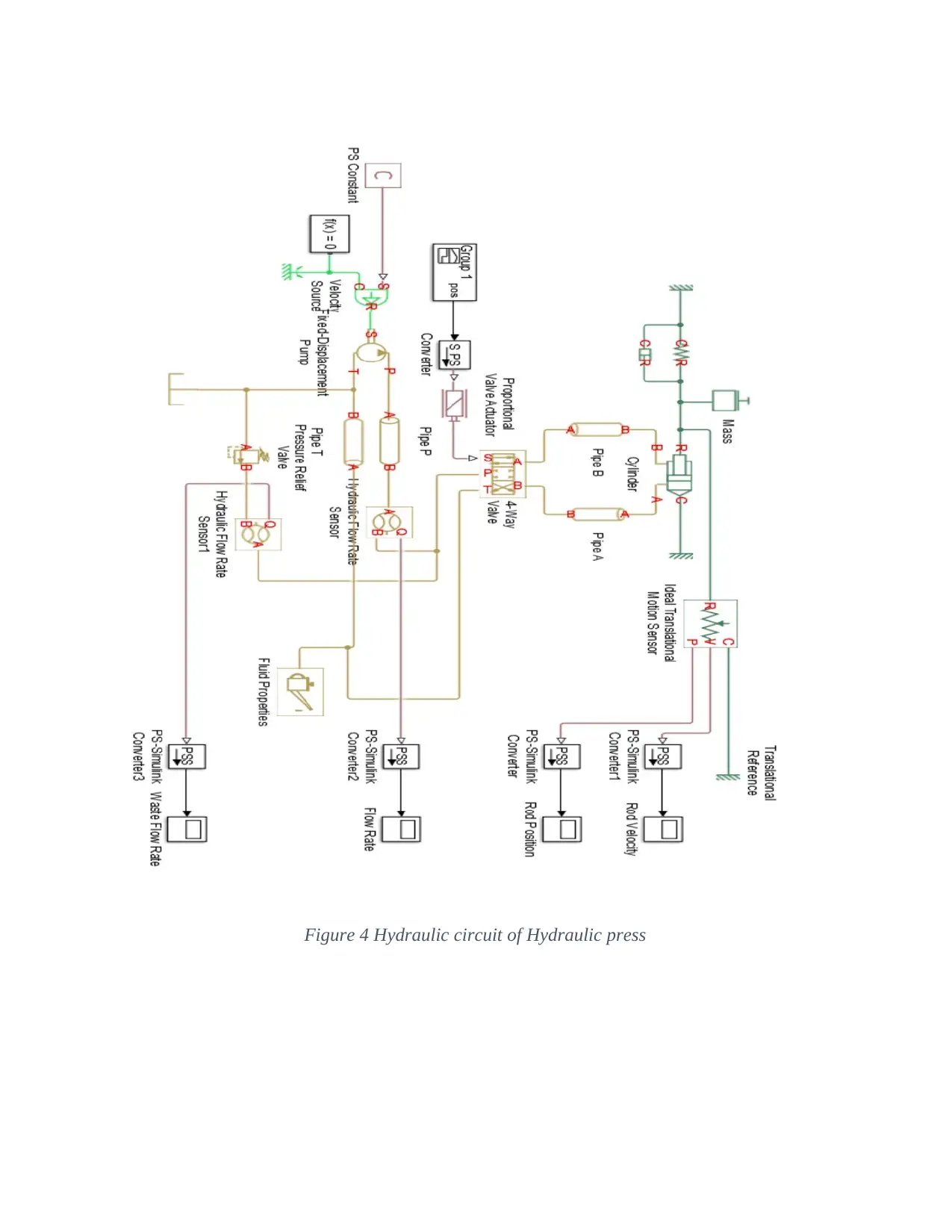
Figure 4 Hydraulic circuit of Hydraulic press
Paraphrase This Document
Need a fresh take? Get an instant paraphrase of this document with our AI Paraphraser
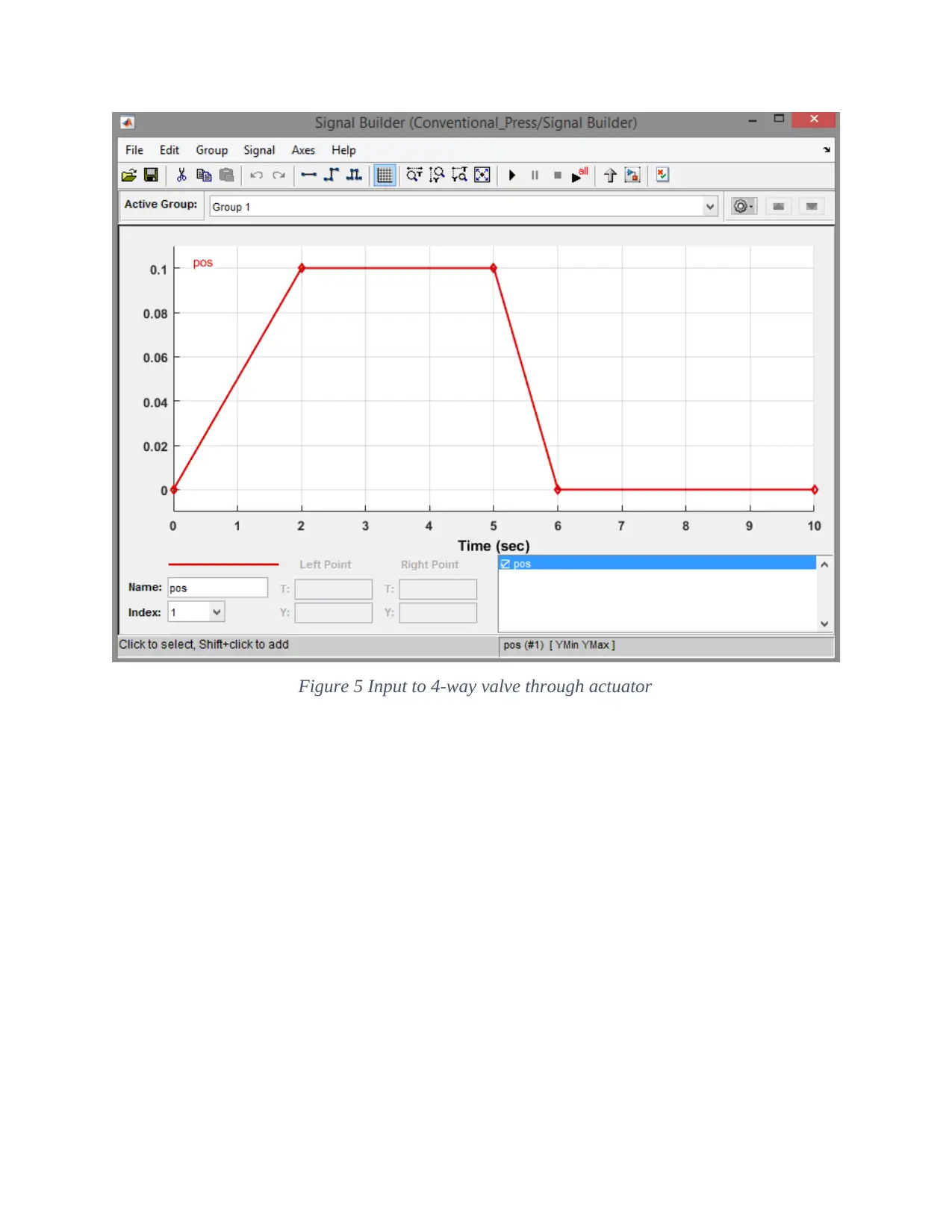
Figure 5 Input to 4-way valve through actuator
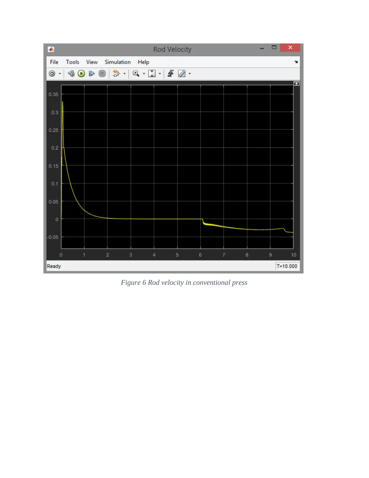
Figure 6 Rod velocity in conventional press
⊘ This is a preview!⊘
Do you want full access?
Subscribe today to unlock all pages.
Trusted by 1+ million students worldwide
1 out of 27


Your All-in-One AI-Powered Toolkit for Academic Success.
+13062052269
info@desklib.com
Available 24*7 on WhatsApp / Email
![[object Object]](/_next/static/media/star-bottom.7253800d.svg)
Unlock your academic potential
Copyright © 2020–2025 A2Z Services. All Rights Reserved. Developed and managed by ZUCOL.