Hydrodynamic Solution: Comprehensive Analysis of Piping Systems Design
VerifiedAdded on 2020/04/21
|13
|484
|121
Homework Assignment
AI Summary
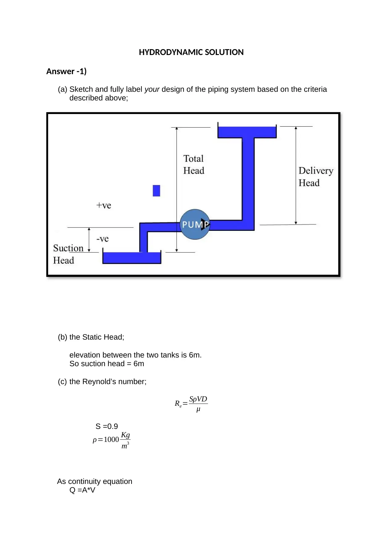
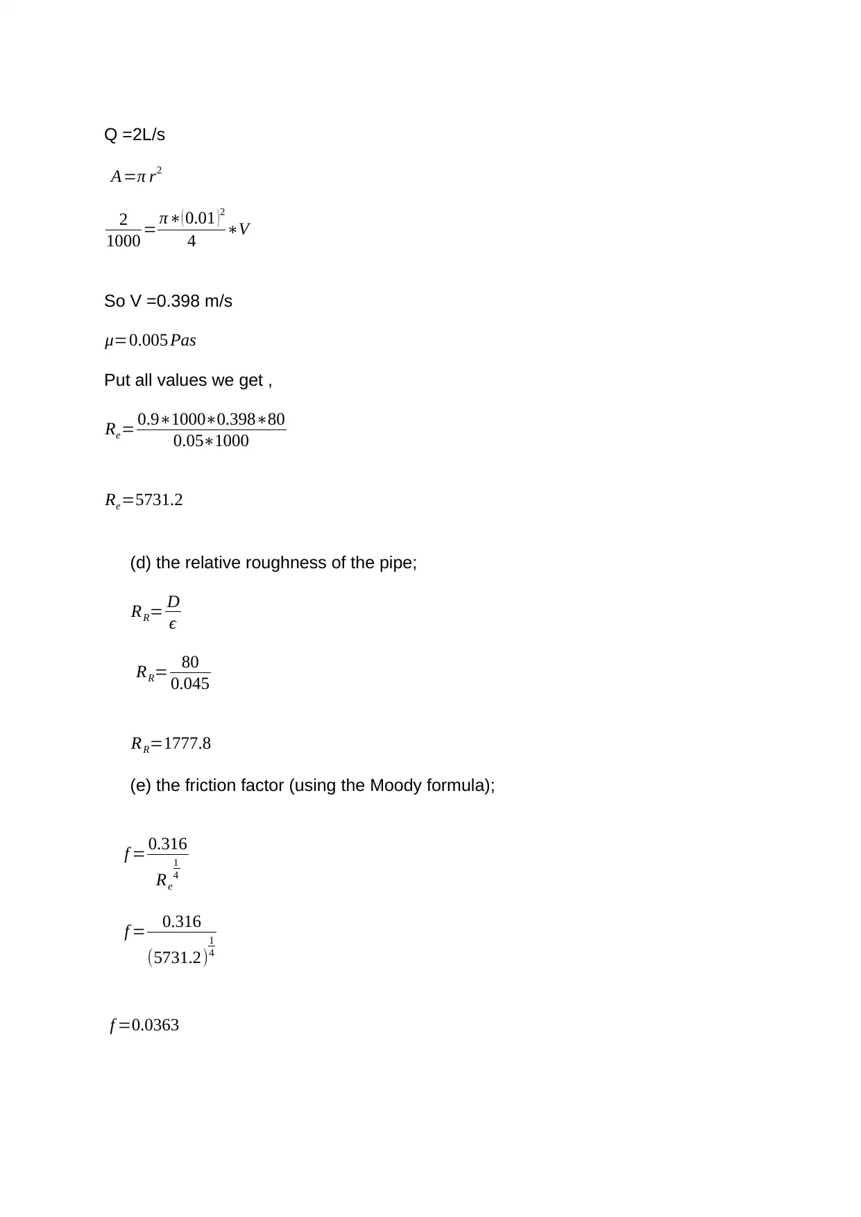
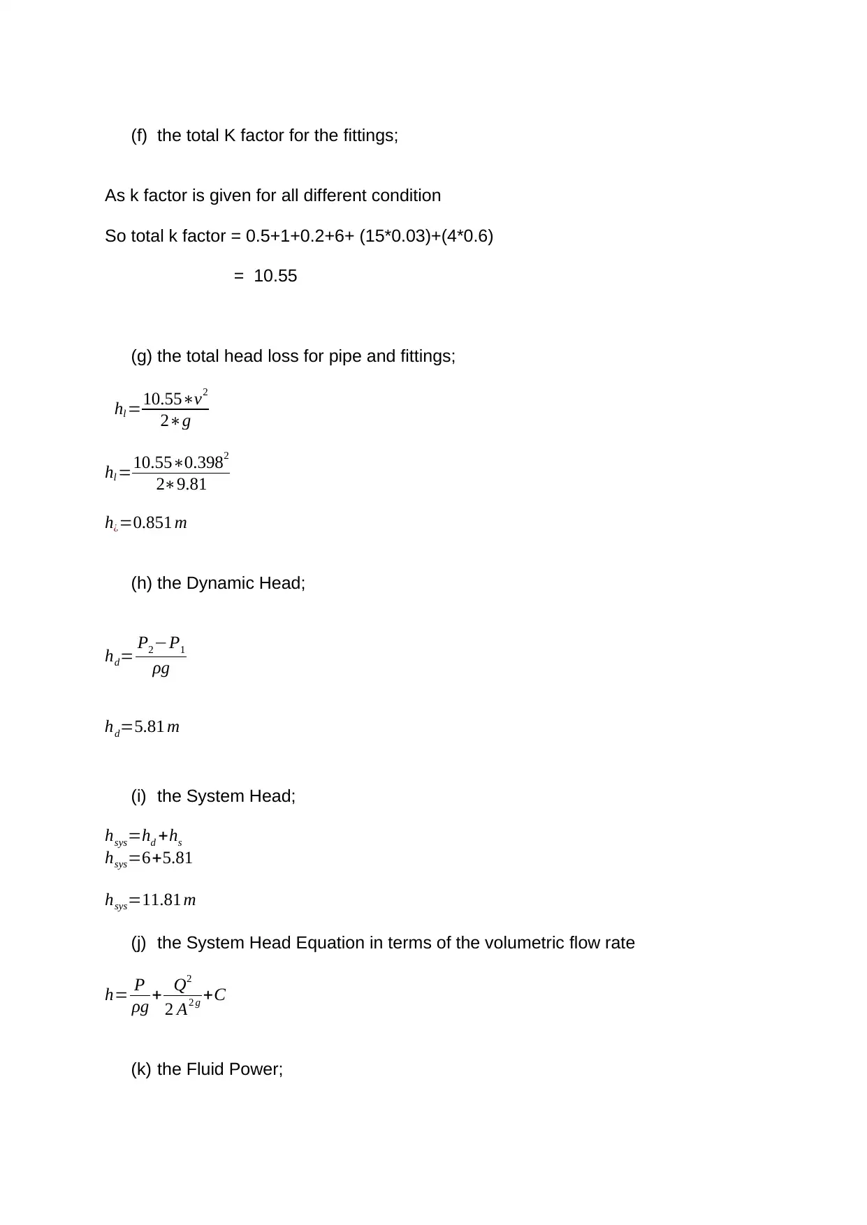
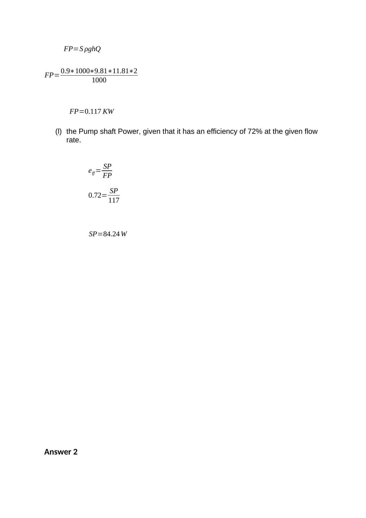
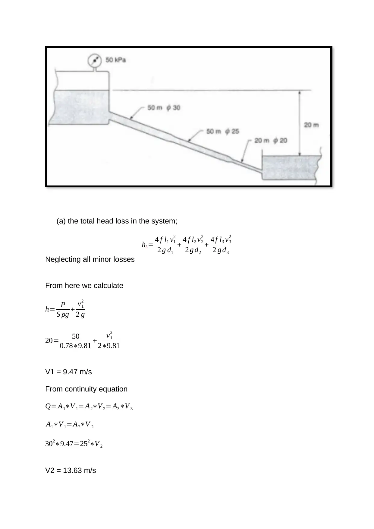
This assignment provides a detailed hydrodynamic solution for the analysis and design of piping systems. It includes calculations for the Reynolds number, friction factor, total head loss, and pump power requirements. The solution covers various aspects such as determining the total head loss in the system, calculating flow velocities in different pipes, and determining the power absorbed due to viscous friction. Furthermore, the assignment delves into the hydraulic radius calculation and the minimum angle of inclination for a channel. The solution uses the Darcy equation, continuity equation, and other relevant formulas to provide a comprehensive analysis of the fluid flow and pressure drop in the system. This assignment is designed to help students understand the principles of fluid dynamics and apply them to real-world engineering problems.
1 out of 13
Related Documents


Your All-in-One AI-Powered Toolkit for Academic Success.
+13062052269
info@desklib.com
Available 24*7 on WhatsApp / Email
![[object Object]](/_next/static/media/star-bottom.7253800d.svg)
Copyright © 2020–2026 A2Z Services. All Rights Reserved. Developed and managed by ZUCOL.