Hydrostatics & Hydraulics Report: OSH4308-15C-1 Project Analysis
VerifiedAdded on 2023/06/09
|10
|1927
|333
Report
AI Summary
This report addresses issues at Acme Manufacturing Company related to industrial storage facilities and fire suppression systems. The study identifies inefficiencies in piping system repair, material selection, and pressure management. Recommendations include implementing proper repair me...
OSH4308-15C-1 Unit 6 Project 1
Hydrostatics and Hydraulic Report
Faisal Ahmed
Columbia Southern University
Hydrostatics and Hydraulic Report
Faisal Ahmed
Columbia Southern University
Paraphrase This Document
Need a fresh take? Get an instant paraphrase of this document with our AI Paraphraser
OSH4308-15C-1 Unit 6 Project 2
Introduction
According to Varsakelis & Papalexandris (2014), hydrostatics is concerned with the
pressure that is exerted by fluids when at rest. The two common fluids are water and air where
water is incompressible while air is compressible. Acme Manufacturing Company deals with
various industrial storage facilities which stores fluids. These facilities are in poor condition
which triggered the need for a study to be conducted on the same. The study, therefore, was aimed
at collecting measurements of various industrial storage facilities and some aspects of the fire
suppression system so as to aid in solving the existing problem.
Report Details
The study found that Acme Manufacturing Company embraces the following measures
for industrial storage:
Piping System Repair
The organization failed to maintain the recommendable standards for the external pipe
surface condition. Whenever the external surface is over damaged such that an elastomeric seal
cannot provide proper sealing forces to the damaged area, the organization was used the wrong
approach. The study, therefore, found out that this will require that the external pipe surface is
repaired with a filler material.
Safe Methods of Repairing
The repair philosophy for critical piping systems in the facility involves replacements.
It further extended to temporary repair, which has always been done until a replacement is
carried out. The major failure in the facility was the fact that repair of safety-critical systems was
OSH4308-15C-1 Unit 6 Project 3
only sufficient in terms of reliability and integrity for normal operating conditions. They were
not in a position to withstand other perceivable conditions.
Conclusion
In conclusion, the study found out the three are inefficiencies in the company when it
comes to the maintenance of industrial storage facilities. This contributed to the corrosion of
storage water tank which led to leakage of water, it also resulted to faulty fire suppression system
due to lack of proper precautions when dealing with the system. It was also established that there
was ignorance when selecting the appropriate material for the piping system and this contributed
to its damage which requires frequent repairs. No precaution was taken regarding the pressure of
the fluids to be held by the pipes which contributed to their busting. It is therefore important that
the management put in place measures to eliminate these inefficiencies in the company.
Recommendation
Basing on the study findings, Acme Manufacturing Company should observe the
following in solving the existing problem:
Piping System Repair
The determinant of the type of repair to be done on a damaged pipe is the external pipe
surface condition. Whenever the external surface is over damaged such that an elastomeric seal
cannot provide proper sealing forces to the damaged area, the stand-off repair may not be
applicable. The study, therefore, found out that this will require that the external pipe surface is
repaired with a filler material.
⊘ This is a preview!⊘
Do you want full access?
Subscribe today to unlock all pages.
Trusted by 1+ million students worldwide
OSH4308-15C-1 Unit 6 Project 4
Types of Repair Components
i) Repair Clamps: this is a metallic patch which is applied to cover small non-leaking
device. The repair involves welding which requires that the damaged area be thick
enough without any defect. This repair type can withstand working pressure of 2000
psi. ‘Stand-off’ repair clamps are the most common forms of repair which are
cylindrical in shape and formed in two half shells. These clamps are sometimes
known as ‘enclosures’ due to the fact that they enclose the defective area within a
sealed pressure. The enclosure sealing is by elastomeric seals at longitudinal joints
and may be energized by any pipe content leakage.
ii) Repair Coupling and Connectors: this is the most economical repair solution in cases
where there is extensive damage. In this case, doing repairs using simple repair
clamps may not be possible because they are available in standard sizes and the
associated costs of producing long clamps are not acceptable. The choice of a
connector is determined by the operating pressure. Sophisticated pipe connectors can
satisfy pressure ratings of up to 10000 psi and pipes with diameters of 48 feet. The
applicability of different repair components for critical piping systems requires
reliability as a key factor. Therefore, the most reliable and applicable repair of the
piping system in the study is the repair coupling and connectors.
Safe Methods of Repairing
The repair philosophy for critical piping systems should involve:
(i) Replacing the likes for likes
(ii) Temporary repair be done until a replacement is carried out
Paraphrase This Document
Need a fresh take? Get an instant paraphrase of this document with our AI Paraphraser
OSH4308-15C-1 Unit 6 Project 5
(iii) Where replacement is not applicable, the only permanent repair should be
done
The repair of safety-critical systems should not only be sufficient in terms of reliability
and integrity for normal operating conditions but be able to withstand other perceivable
conditions.
Composite Materials for Repair
(i) An external corrosion without structural integrity and leakage should be restored with
suitable surface preparation through the application of composite unwrap to reduce
deterioration.
(ii) Where there is internal loss through corrosion with no leakage and need to restore
structural integrity exists, damage assessment and composite repair option must be
taken into account.
(iii) Structural integrity should be restored where there is external damage such as fretting
and dents.
Types of Composite Repair
Composite repair types fall into two categories namely bandage and engineered. Bandage
type repair involves the application of material that can be easily applied by facility personnel
while the Engineered type repairs are designed and specified on a bespoke basis whereby repair
is carried out by specialists. The two repairs entail the application of overwrap to the damaged
area so as to reinforce the strength or integrity of the pipe wall remaining. Whenever an external
metal loss is being repaired, the composite sleeve must involve the application of a form of the
load before applying the composite sleeve.
(a) Water Storage Tanks
OSH4308-15C-1 Unit 6 Project 6
Water storage tanks are very important since they ensure a constant supply of water.
The installation of float control valves enables automated control of water levels in tanks. The
valve is fitted with a float mechanism designed to regulate and monitor the top water level in the
tank so as to ensure constant water supply. This reduces cost and it is less time consuming
compared to other alternative methods. Therefore, a correct installation of control valves ensures
accurate readings and functioning.
Specific Valves to be installed
(i) The standard control tank valves are designed to be installed horizontally but in case
one wants a vertical installation, they should indicate it when placing an order so as to
enable the engineers to configure the bonnet.
(ii) When isolating the fill tank control valve, isolation valves should be fitted before and
after to ensure maintenance of the necessary valve intervals.
(iii) When externally installing a tank fill control valve, ensure that the valve body is
covered fully to avoid the formation of ice inside
(iv) Determine the installation position early to enable easy access to the valve for body
maintenance and other components
(v) Install a duty stand-by arrangement if the valve is fitted to a critical supply line to
enable online maintenance
(b) Fire Suppression Systems
Mcneil & Lattimer (2016) argue that the difference between a sprinkler and a fire
suppression system is on how they extinguish the fire. The sprinkler makes use of water to
control and extinguish the fire which a suppression system uses chemicals and gases to
⊘ This is a preview!⊘
Do you want full access?
Subscribe today to unlock all pages.
Trusted by 1+ million students worldwide
OSH4308-15C-1 Unit 6 Project 7
extinguish the fire. It is, therefore, the better option in some cases where water would cause
damage to property.
Types of Suppression Systems
(i) The automatic fire suppression systems control and extinguish the fire without
human intervention. The examples of automatic fire suppression systems include
the fire sprinkler system, condensed aerosol system, and the gaseous fire
suppression.
(ii) Carbon dioxide- this works quickly and efficiently but it is extremely dangerous
to humans
(iii) Wet chemical fire suppression- this is ideal for kitchen applications
(iv) Dry chemical suppression-it’s for extinguishing flames caused by combustible
fluids
(v) Engineered Fire Suppression System: these are commonly used for larger
installations such as public and private buildings
Paraphrase This Document
Need a fresh take? Get an instant paraphrase of this document with our AI Paraphraser
OSH4308-15C-1 Unit 6 Project 8
Piping repair calculation
The total pressure of the pipe at 35
As per OSHA guideline the pressure at point is given by the formula P = ρ h g where h is height
in ft
Putting the value of h is given by formula, P = ρ h g
Sice it is given that the property of liquid is like water then its density will also
similar to water and it is = 62.428 lb/ft3 = h = 35 ft, and value of g = 70.932 lb.ft/s2
Putting the value P = 62.428 x (60-35) x 70.932 = 110703 lb/ft2 Ans
Distribution system
The outlet velocity from a tank is calculated as V = CV (2gH)1/2 CV = 0.97
G = 70.932 ft/sec2, H is the height of tank
Putting the value, we get velocity
For H = 24 ft
V = 0.97 x (2 x 70.932*24)1/2 = 56.6 ft/sec
For H = 18
V = 0.97 x (2 x 70.932*18)1/2 = 49.0167 ft/sec
For H = 12
V = 0.97 x (2 x 70.932*12)1/2 = 40.022 ft/sec
For H = 12
V = 0.97 x (2 x 70.932*6)1/2 = 28.3 ft/sec Ans
OSH4308-15C-1 Unit 6 Project 9
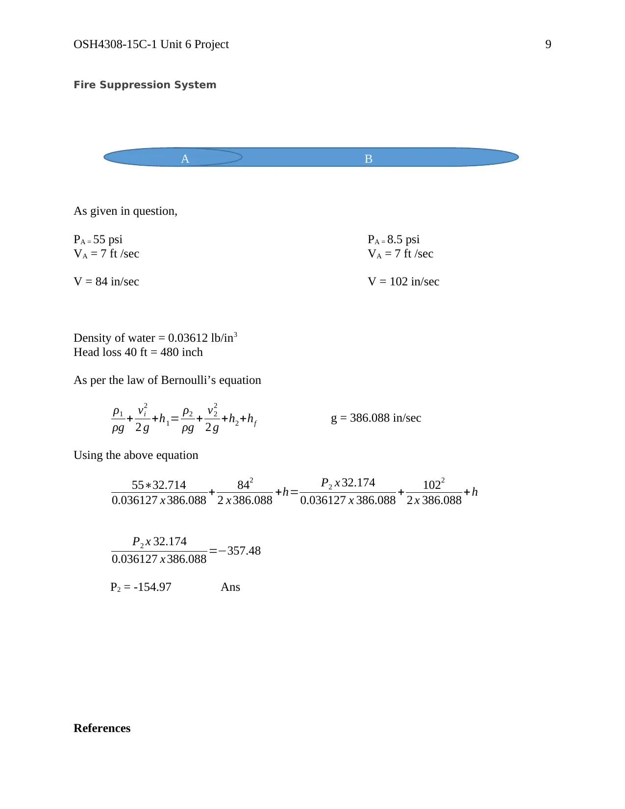
Fire Suppression System
As given in question,
PA = 55 psi PA = 8.5 psi
VA = 7 ft /sec VA = 7 ft /sec
V = 84 in/sec V = 102 in/sec
Density of water = 0.03612 lb/in3
Head loss 40 ft = 480 inch
As per the law of Bernoulli’s equation
ρ1
ρg + vi
2
2 g +h1= ρ2
ρg + v2
2
2 g +h2 +hf g = 386.088 in/sec
Using the above equation
55∗32.714
0.036127 x 386.088 + 842
2 x 386.088 +h= P2 x 32.174
0.036127 x 386.088 + 1022
2 x 386.088 + h
P2 x 32.174
0.036127 x 386.088 =−357.48
P2 = -154.97 Ans
References
A B
⊘ This is a preview!⊘
Do you want full access?
Subscribe today to unlock all pages.
Trusted by 1+ million students worldwide
OSH4308-15C-1 Unit 6 Project
10
Mcneil, J. G., & Lattimer, B. Y. (2016). Autonomous fire suppression system for use in high and
low visibility environments by visual servoing. Fire Technology, 52(5), 1343-1368.
doi:http://dx.doi.org/10.1007/s10694-016-0564-8
Varsakelis, C., & Papalexandris, M. V. (2014). Existence of solutions to a continuum model for
hydrostatics of fluid-saturated granular materials. Applied Mathematics Letters, 35, 77-
81.
1 out of 10
Your All-in-One AI-Powered Toolkit for Academic Success.
+13062052269
info@desklib.com
Available 24*7 on WhatsApp / Email
![[object Object]](/_next/static/media/star-bottom.7253800d.svg)
Unlock your academic potential
© 2024 | Zucol Services PVT LTD | All rights reserved.