IGTB Inverter for Traction System in Railway Engineering
VerifiedAdded on 2023/06/16
|16
|3861
|217
AI Summary
This article discusses the use of Insulated Gate Bipolar Transistor (IGTB) inverter technology for traction system in railway engineering. It explains the characteristics of IGTB inverters, their advantages over conventional GTO inverters, and their use in improving energy efficiency and performance of trams. The article also includes a comparison between trams powered by IGTB inverters and those powered by GTO inverters, and an analysis of energy consumption and operation performance.
Contribute Materials
Your contribution can guide someone’s learning journey. Share your
documents today.

Railway System Engineering 1
RAILWAY SYSTEM ENGINEERING
By Name
Course
Instructor
Institution
Location
Date
RAILWAY SYSTEM ENGINEERING
By Name
Course
Instructor
Institution
Location
Date
Secure Best Marks with AI Grader
Need help grading? Try our AI Grader for instant feedback on your assignments.
Railway System Engineering 2
Executive Summary
With the continued tremendous development experienced in the automotive industry in the
recent past, stringent constraints have been experienced on power electronic systems with
particular focus to solutions that are cost effective (Baliga 2015, p. 231). Hybrid electric vehicles
and electric vehicles present are associated with technical challenges following their high
demand for high currents and voltages required for their operation. These challenges are among
them the conversion power that exceeds the capacity normally associated with vehicle electrical
and electronic systems.
Due to the every rising demand for fuel energy efficiency, a need for power control unit that is
not only lightweight but also of small volume in hybrid electric vehicles and electronic vehicles.
In this concept design, the focus is on the Insulated Gate Bipolar Transistor. Insulated Gate
Bipolar Transistor is a choice of power device that works with the power control unit and is
made up of a booster converter besides two inverters. This project scope is not on the design of a
completely new vehicle but instead establishing a better alternative for the conventional GTO in
the traction system of a vehicle. IGTB requires comparatively low switching frequency that is up
to a maximum of 20 kHz with high current (Luvishis 2010, p. 325).
The booster inverter assures a high switching frequency to the tune of 170 kHz and a
comparatively lower current. This power device while used in the motor of a traction system
would enhance energy efficiency and thus improve on the performance of the vehicle. It reduces
to significant levels or even eliminates energy losses through heat that occurs because of high
voltage and low frequency switching that is identifiable with the convention GTO (Diamandis
Railway System Engineering 3
2012, p. 568). As a result of these properties, IGTB inverters have become a cost reduction
solution thereby enhancing affordability and profit maximization in the automotive industry.
Due to their high internal electric fields and subjectivity to large temperatures at the junctions
when in operation, IGTB are confidently a design solution for a more reliable and efficient
hybrid electric vehicles and electric vehicles. Also incorporated in this project scope is the duty
analysis, energy consumption and operation performance of a motor of the traction system on the
IGTB technology in comparison with another motor using GTO conventional approach. From
the design and analysis, IGTB inverter comes out to be a better solution to the reliability,
effectiveness and efficiency of the traction system of a tram (Kassab 2015, p. 278).
Introduction
With the increasing concern on energy, consumption and usage among the various sectors of the
economy around the world, the metro system has not been left behind either. Following the
services, this system offers to the world population and it large coverage, energy efficiency has
become a fundamental issue as a need to champion for sustainability as well as has the operation
costs at an affordable level that would leave the system in a capacity to remain in service (Baliga
2015, p. 188). It is for this reason that has led to the need for in-depth research on the most
energy efficient strategy for the metro system- strategies that would see the amount of energy
consumed reduced to significantly manageable levels. The research has also formed the
foundation upon which an energy efficient traction system can be designed to help in achieving
this mission (Bugarski 2006, p. 268).
Railway System Engineering 4
The main approaches that can be used in ascertaining energy efficiency and reduced carbon
dioxide emissions into the atmosphere include either an increase in the electric traction usage
that would translate into reduced usages of diesel traction that is associated with major losses in
the traction chain. This is a technology that is already running, and the metro systems have been
deploying it for some time now as an energy efficiency strategy (Clarke 2008, p. 369). Using
AC asynchronous traction motor that has IGBT inverters is yet another technology and hence a
design concept that would help in the achievement of this dream.
The traction motors act as the source of energy that is needed by the wheels to operate and the
electricity into the traction motors is generated from the catenary hence implying a difference in
the equipment that would be required to accomplish the design (Diamandis 2012, p. 458).
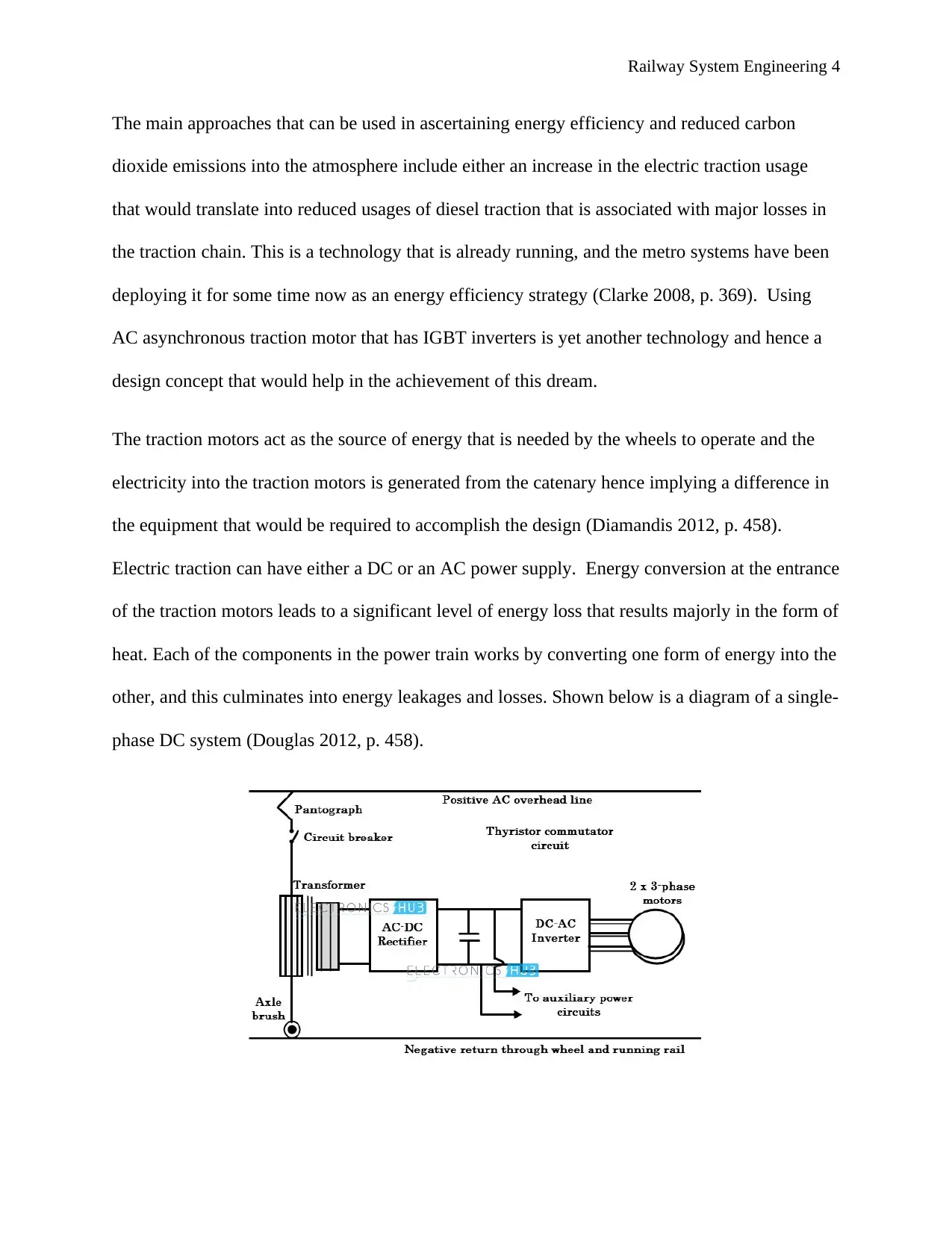
Electric traction can have either a DC or an AC power supply. Energy conversion at the entrance
of the traction motors leads to a significant level of energy loss that results majorly in the form of
heat. Each of the components in the power train works by converting one form of energy into the
other, and this culminates into energy leakages and losses. Shown below is a diagram of a single-
phase DC system (Douglas 2012, p. 458).
Secure Best Marks with AI Grader
Need help grading? Try our AI Grader for instant feedback on your assignments.
Railway System Engineering 5
The concept design whose focus will mainly be on the electric train will give significant
attention to the various components of the system and the modifications that can be done to them
to ensure higher energy efficiency. Among the components that would be given an in-depth
analysis and the results of the modification, including the transformers, inverters as well as the
traction motor (Fitzgerald 2017, p. 594). A heavier transformer is more efficient than a lighter
one. A heavier transformer is able to make use of superconducting material while a transformer
of medium frequency operates on the principle that an increase in frequency increases the
induction. This principle would enable it to save on possible losses and mass. A replacement of
the GTOs with IGBTs would see a higher frequency achieved. Other design approaches and
concepts would be traction motors modification through the use of an asynchronous motor or
even a transversal flux (Kassab 2015, p. 256).
IGBT inverters for traction system
Insulated Gate Bipolar Transistors is a well-established technology in the field of electronics and
can be used in the place of the previous technology-GTO. IGBTs operate at very high currents,
which is usually more than 1000A as opposed to other conventional transistors. The high
operation current makes them produce a very high switching frequency thereby aiding in the
reduction current and reduced energy losses through heat. The increased switching frequency
also helps in the reduction of the levels of noise in the traction and smoothens the process of
acceleration (Harris 2010, p. 589).
IGBT inverters aids in the prevention of regenerative braking of the locomotive by supplying
into the traction system regeneration energy, which is generated when the train is braking. The
regeneration energy supplied forms a fundamental aspect of energy saving as well as
Railway System Engineering 6
environmental conservation by reducing the burden on the effective as a result of effectiveness in
the usage of energy (Escoubet 2012, p. 456).
By combining the properties of Bipolar Junction Transistor and Field Effect Transistor, IGBT
inverters achieves a high input impedance and high speeds of switching as of a Field Effect
Transistor and a low voltage of saturation as of a bipolar transistor. By combining these two
properties, IGBT inverters take the best of the parts of the two conventional transistors. The
resultant device achieved is able to contain emission of very large currents with a virtual gate
current drive of zero (Diamandis 2012, p. 621). The technology brings together the technology
of insulated gate of MOSFET and characteristics of output performance of a bipolar transistor.
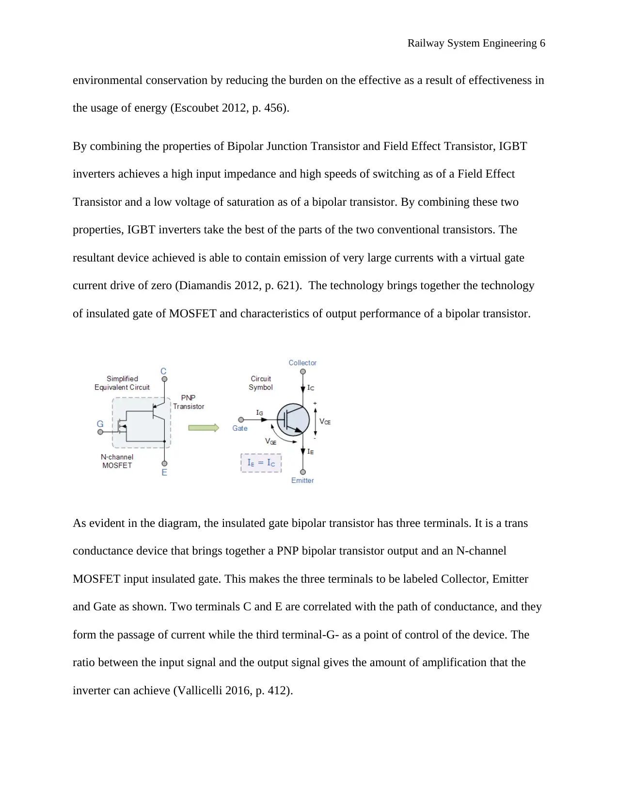
As evident in the diagram, the insulated gate bipolar transistor has three terminals. It is a trans
conductance device that brings together a PNP bipolar transistor output and an N-channel
MOSFET input insulated gate. This makes the three terminals to be labeled Collector, Emitter
and Gate as shown. Two terminals C and E are correlated with the path of conductance, and they
form the passage of current while the third terminal-G- as a point of control of the device. The
ratio between the input signal and the output signal gives the amount of amplification that the
inverter can achieve (Vallicelli 2016, p. 412).
Railway System Engineering 7
Characteristics of IGTB inverter
Since IGTB inverter is controlled by voltage, it only needs very low voltage to flow through the
Gate so as to maintain the conduction through the device. This device only switches current in
the forward direction that is from the Collector to the Emitter. It has the similar operation
principle as well as circuits for Gate drive as the N-channel power of MOSFET. The only
difference comes in at the conduction channel (Rosenberger 2016, p. 302). For the case of IGTB
inverter, the main conducting channel is in a very small ‘ON’ state when current flows through
the device. This makes the ratings of the current of this device very high.
There is direct proportionality between the torque generated by the motor, and the magnetic field
produced by the stator hence the higher the voltage applied the higher the angular velocity stator
flux product. In this regard, the flux generated by the stator would be directly proportional to
frequency and voltage of the supply (Publishers) 2004, p. 225). This means when there is a
variation of the voltage, and the frequency at the same ratio keeps the torque constant along the
speed range.
In this light, V/F remains to be the most common technique used in the control of the speed of
the induction motor. The higher the developed torque, the higher the V/F ratio. The torque
produced by the motor would be found to remain constant if the voltage and the frequency are
varied along the provided range of speed. At the base speed, the frequency and the voltage values
are found to be at maximum (Thackara 2006, p. 301). It is possible to drive the inductor motor at
speeds above the base speed but this would only the frequency changes and the voltage remains
constant.
Paraphrase This Document
Need a fresh take? Get an instant paraphrase of this document with our AI Paraphraser
Railway System Engineering 8
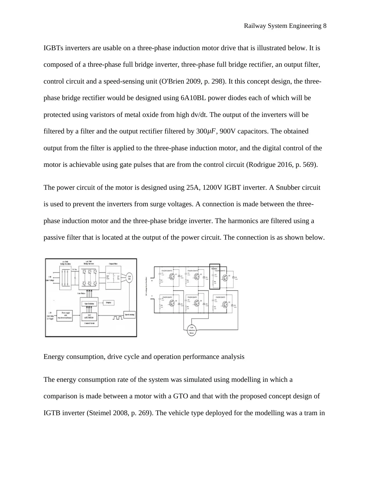
IGBTs inverters are usable on a three-phase induction motor drive that is illustrated below. It is
composed of a three-phase full bridge inverter, three-phase full bridge rectifier, an output filter,
control circuit and a speed-sensing unit (O'Brien 2009, p. 298). It this concept design, the three-
phase bridge rectifier would be designed using 6A10BL power diodes each of which will be
protected using varistors of metal oxide from high dv/dt. The output of the inverters will be
filtered by a filter and the output rectifier filtered by 300μF, 900V capacitors. The obtained
output from the filter is applied to the three-phase induction motor, and the digital control of the
motor is achievable using gate pulses that are from the control circuit (Rodrigue 2016, p. 569).
The power circuit of the motor is designed using 25A, 1200V IGBT inverter. A Snubber circuit
is used to prevent the inverters from surge voltages. A connection is made between the three-
phase induction motor and the three-phase bridge inverter. The harmonics are filtered using a
passive filter that is located at the output of the power circuit. The connection is as shown below.
Energy consumption, drive cycle and operation performance analysis
The energy consumption rate of the system was simulated using modelling in which a
comparison is made between a motor with a GTO and that with the proposed concept design of
IGTB inverter (Steimel 2008, p. 269). The vehicle type deployed for the modelling was a tram in
Railway System Engineering 9
which the performance was compared against another filtered with GTO inverters. The analysis
compared two trams, GTO powered, and IGTB motor powered trams.
Tram A Tram B
Motors IGTB inverter motor GTO inverter motor
Mass 22 tonnes 16 tonnes
Capacity 200 passengers 15.7m
Length 29m 78 passengers
The table above gives a comparison between the two trams. Tram A deploys the IGTB inverter
technology in the motors while tram B deploys the convention GTO inverters. Tram A is longer
than Tram B at 29m and thus as can be seen from the table has a larger capacity in as much as
the difference between their weights is a bit insignificant which defines one of its key advantages
of design. The extra capacity of Tram A allows it to have a higher number of passengers on
board on a single trip (Nash 2015, p. 471). This means this tram is likely to achieve higher and
better consumption figures when in full capacity with regard to energy per passenger kilometer.
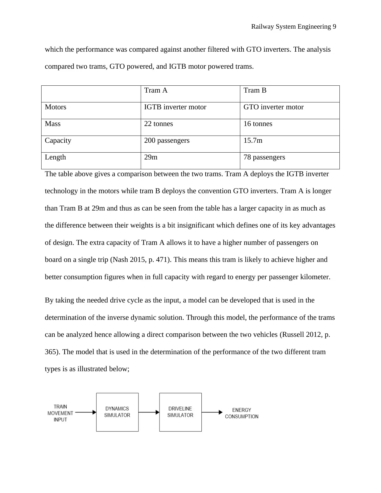
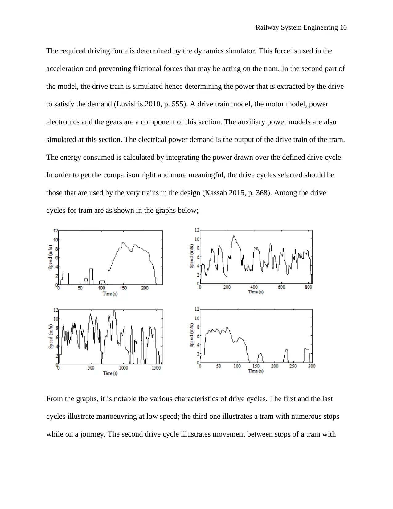
By taking the needed drive cycle as the input, a model can be developed that is used in the
determination of the inverse dynamic solution. Through this model, the performance of the trams
can be analyzed hence allowing a direct comparison between the two vehicles (Russell 2012, p.
365). The model that is used in the determination of the performance of the two different tram
types is as illustrated below;
Railway System Engineering 10
The required driving force is determined by the dynamics simulator. This force is used in the
acceleration and preventing frictional forces that may be acting on the tram. In the second part of
the model, the drive train is simulated hence determining the power that is extracted by the drive
to satisfy the demand (Luvishis 2010, p. 555). A drive train model, the motor model, power
electronics and the gears are a component of this section. The auxiliary power models are also
simulated at this section. The electrical power demand is the output of the drive train of the tram.
The energy consumed is calculated by integrating the power drawn over the defined drive cycle.
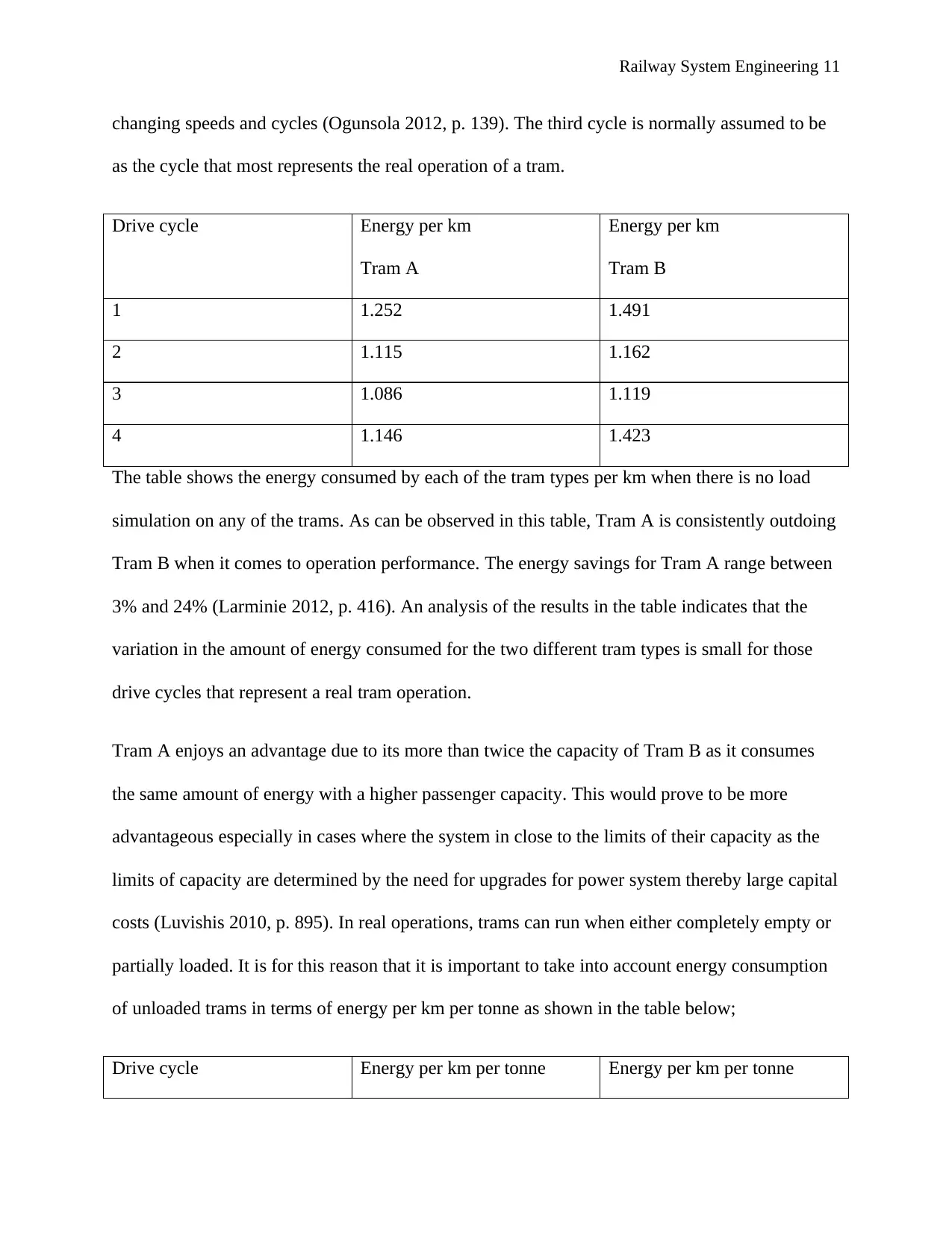
In order to get the comparison right and more meaningful, the drive cycles selected should be
those that are used by the very trains in the design (Kassab 2015, p. 368). Among the drive
cycles for tram are as shown in the graphs below;
From the graphs, it is notable the various characteristics of drive cycles. The first and the last
cycles illustrate manoeuvring at low speed; the third one illustrates a tram with numerous stops
while on a journey. The second drive cycle illustrates movement between stops of a tram with
Secure Best Marks with AI Grader
Need help grading? Try our AI Grader for instant feedback on your assignments.
Railway System Engineering 11
changing speeds and cycles (Ogunsola 2012, p. 139). The third cycle is normally assumed to be
as the cycle that most represents the real operation of a tram.
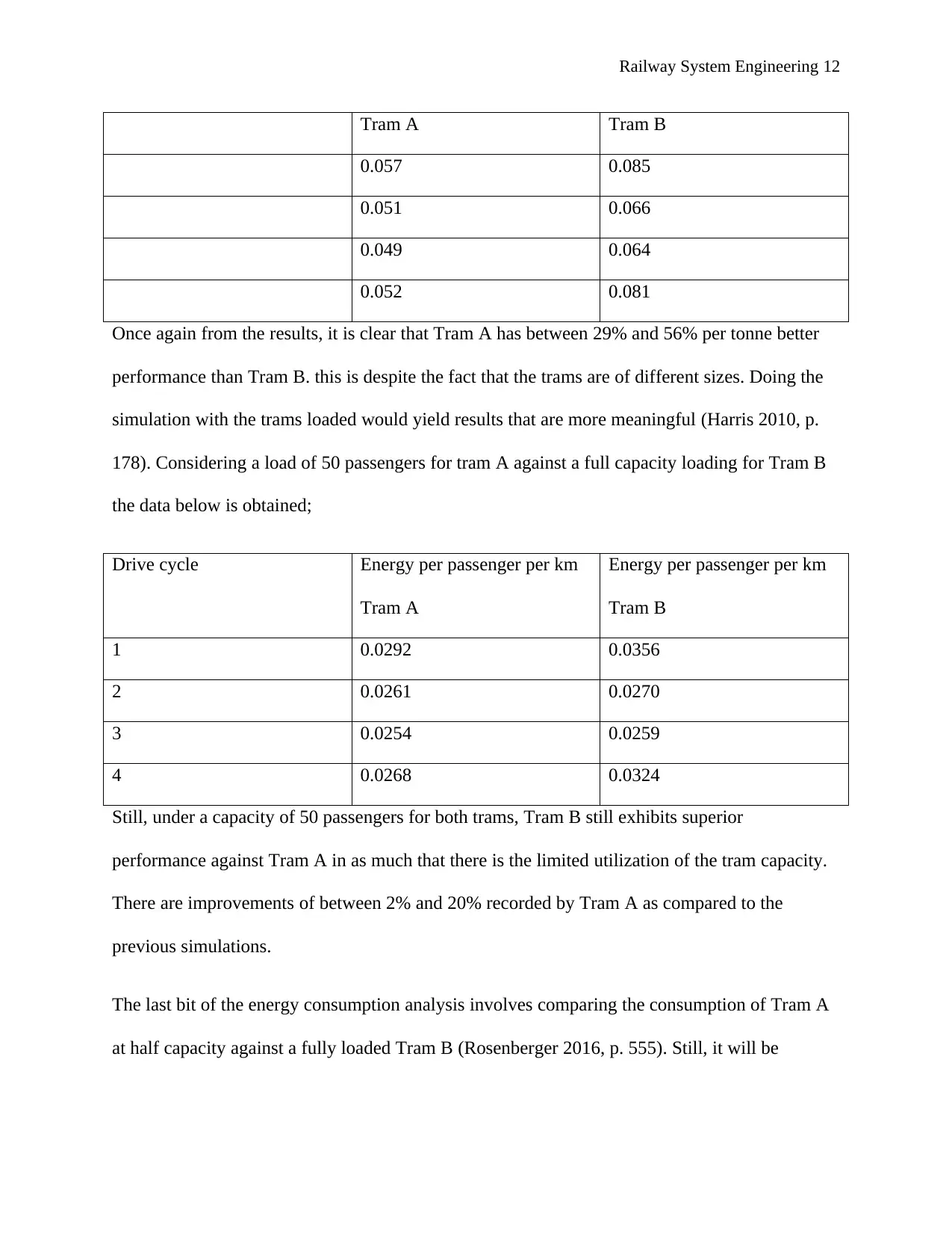
Drive cycle Energy per km
Tram A
Energy per km
Tram B
1 1.252 1.491
2 1.115 1.162
3 1.086 1.119
4 1.146 1.423
The table shows the energy consumed by each of the tram types per km when there is no load
simulation on any of the trams. As can be observed in this table, Tram A is consistently outdoing
Tram B when it comes to operation performance. The energy savings for Tram A range between
3% and 24% (Larminie 2012, p. 416). An analysis of the results in the table indicates that the
variation in the amount of energy consumed for the two different tram types is small for those
drive cycles that represent a real tram operation.
Tram A enjoys an advantage due to its more than twice the capacity of Tram B as it consumes
the same amount of energy with a higher passenger capacity. This would prove to be more
advantageous especially in cases where the system in close to the limits of their capacity as the
limits of capacity are determined by the need for upgrades for power system thereby large capital
costs (Luvishis 2010, p. 895). In real operations, trams can run when either completely empty or
partially loaded. It is for this reason that it is important to take into account energy consumption
of unloaded trams in terms of energy per km per tonne as shown in the table below;
Drive cycle Energy per km per tonne Energy per km per tonne
Railway System Engineering 12
Tram A Tram B
0.057 0.085
0.051 0.066
0.049 0.064
0.052 0.081
Once again from the results, it is clear that Tram A has between 29% and 56% per tonne better
performance than Tram B. this is despite the fact that the trams are of different sizes. Doing the
simulation with the trams loaded would yield results that are more meaningful (Harris 2010, p.
178). Considering a load of 50 passengers for tram A against a full capacity loading for Tram B
the data below is obtained;
Drive cycle Energy per passenger per km
Tram A
Energy per passenger per km
Tram B
1 0.0292 0.0356
2 0.0261 0.0270
3 0.0254 0.0259
4 0.0268 0.0324
Still, under a capacity of 50 passengers for both trams, Tram B still exhibits superior
performance against Tram A in as much that there is the limited utilization of the tram capacity.
There are improvements of between 2% and 20% recorded by Tram A as compared to the
previous simulations.
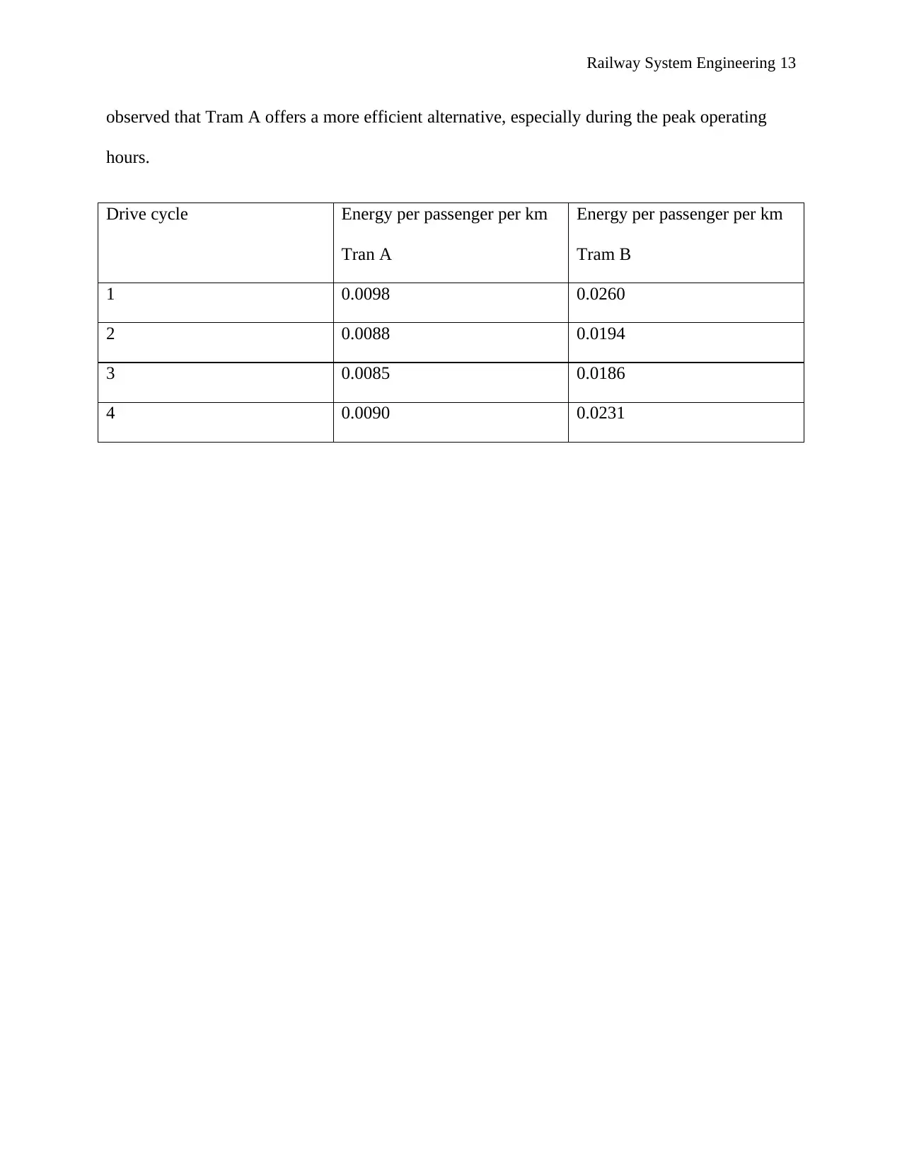
The last bit of the energy consumption analysis involves comparing the consumption of Tram A
at half capacity against a fully loaded Tram B (Rosenberger 2016, p. 555). Still, it will be
Railway System Engineering 13
observed that Tram A offers a more efficient alternative, especially during the peak operating
hours.
Drive cycle Energy per passenger per km
Tran A
Energy per passenger per km
Tram B
1 0.0098 0.0260
2 0.0088 0.0194
3 0.0085 0.0186
4 0.0090 0.0231
observed that Tram A offers a more efficient alternative, especially during the peak operating
hours.
Drive cycle Energy per passenger per km
Tran A
Energy per passenger per km
Tram B
1 0.0098 0.0260
2 0.0088 0.0194
3 0.0085 0.0186
4 0.0090 0.0231
Paraphrase This Document
Need a fresh take? Get an instant paraphrase of this document with our AI Paraphraser
Railway System Engineering 14
References
Baliga, BJ 2015, The IGBT Device: Physics, Design and Applications of the Insulated Gate
Bipolar Transistor, 3rd edn, William Andrew, Paris.
Bugarski, AD 2006, Effectiveness of Selected Diesel Particulate Matter Control Technologies
for Underground Mining Applications: Isolated Zone Study, 2003, 7th edn, Pennsylvania State
University, New York.
Clarke, J 2008, Jane's World Railways 2008-2009, 50th edn, Jane's Information Group, Oxford.
Diamandis, PH 2012, Abundance: The Future Is Better Than You Think, 5th edn, Simon and
Schuster, London.
Douglas, DG 2012, The Social Construction of Technological Systems: New Directions in the
Sociology and History of Technology, 5th edn, MIT Press, Paris.
Escoubet, CP 2012, The Cluster and Phoenix Missions, 5th edn, Springer Science & Business
Media, Manchester.
Fitzgerald, RW 2017, Fire Performance Analysis for Buildings, 5th edn, John Wiley & Sons,
London.
Harris, K 2010, Jane's World Railways, 1999-2000, 41st edn, Jane's Information Group, London.
Hughes, TP 2013, Networks of Power: Electrification in Western Society, 1880-1930, 5th edn,
JHU Press, New Delhi.
Kassab, M 2015, Communication Technologies for Vehicles: 8th International Workshop,
Nets4Cars/Nets4Trains/Nets4Aircraft 2015, Sousse, Tunisia, May 6-8, 2015. Proceedings, 6th
Railway System Engineering 15
edn, Springer, New York.
Katoen, J-P 2011, Lectures on Formal Methods and Performance Analysis: First EEF/Euro
Summer School on Trends in Computer Science Berg en Dal, The Netherlands, July 3-7, 2000.
Revised Lectures, Volume 1, 8th edn, Springer Science & Business Media, London.
Larminie, J 2012, Electric Vehicle Technology Explained, 2nd edn, John Wiley & Sons,
Manchester.
London, RSO 2007, Philosophical Transactions of the Royal Society of London: Biological
sciences, Volume 362, 5th edn, Royal Society of London, London.
Luvishis, A 2010, Hybrid Rail Vehicles, 6th edn, Lulu.com, Kansas.
McDonnell, G 2015, Locomotives: The Modern Diesel and Electric Reference, 2nd edn, Boston
Mills Press, New York.
Nash, C 2015, Handbook of Research Methods and Applications in Transport Economics and
Policy, 4th edn, Edward Elgar Publishing, New York.
O'Brien, T 2009, The Things They Carried, 1st edn, Houghton Mifflin Harcourt, Chicago.
Ogunsola, A 2012, Electromagnetic Compatibility in Railways: Analysis and Management, 10th
edn, Springer Science & Business Media, Lagos.
Publishers), P(E 2004, New Trains: IMechE Conference Transactions 2003-6, 6th edn, John
Wiley & Sons, New York.
Rodrigue, J-P 2016, The Geography of Transport Systems, 4th edn, Taylor & Francis, London.
Railway System Engineering 16
Rosenberger, M 2016, The Dynamics of Vehicles on Roads and Tracks: Proceedings of the 24th
Symposium of the International Association for Vehicle System Dynamics (IAVSD 2015), Graz,
Austria, 17-21 August 2015, 4th edn, CRC Press, New York.
Russell, CT 2012, EDN, Electrical Design News, Volume 47, Issues 25-28, 15th edn, Rogers
Publishing Company, Oxford.
Steimel, A 2008, Electric Traction - Motive Power and Energy Supply: Basics and Practical
Experience, 5th edn, Oldenbourg Industrieverlag, Salt Lake.
Thackara, J 2006, In the Bubble: Designing in a Complex World, 4th edn, MIT Press, New
Delhi.
Vallicelli, A 2016, Advances in Human Aspects of Transportation: Proceedings of the AHFE
2016 International Conference on Human Factors in Transportation, July 27-31, 2016, Walt
Disney World®, Florida, USA, 4th edn, Springer, Florida.
1 out of 16
Your All-in-One AI-Powered Toolkit for Academic Success.
+13062052269
info@desklib.com
Available 24*7 on WhatsApp / Email
![[object Object]](/_next/static/media/star-bottom.7253800d.svg)
Unlock your academic potential
© 2024 | Zucol Services PVT LTD | All rights reserved.

