Image Georeferencing and Orthorectification - ENVI 5.4 Report
VerifiedAdded on  2023/04/04
|9
|1091
|134
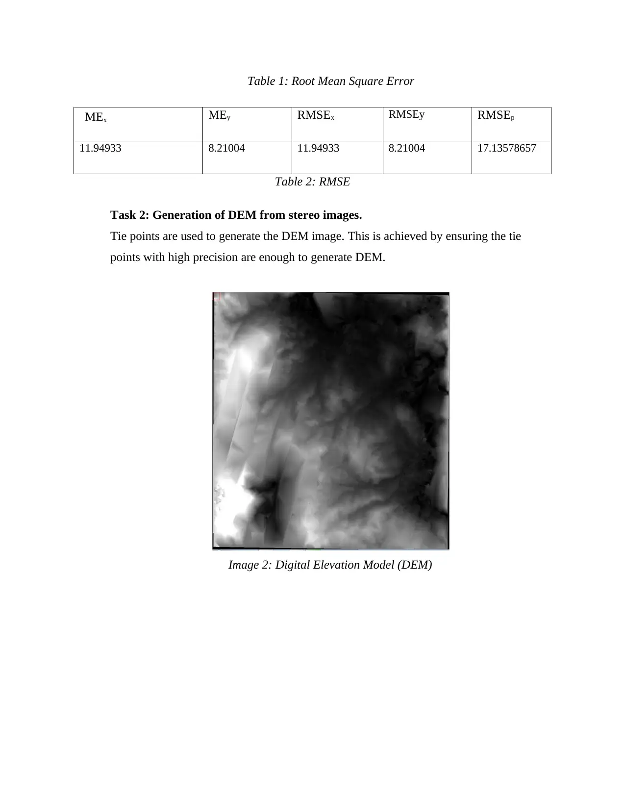
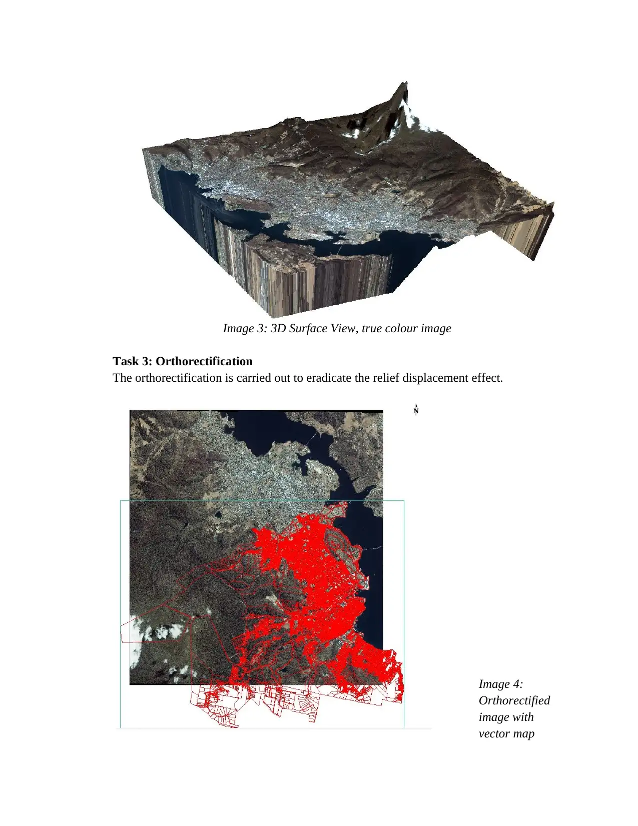
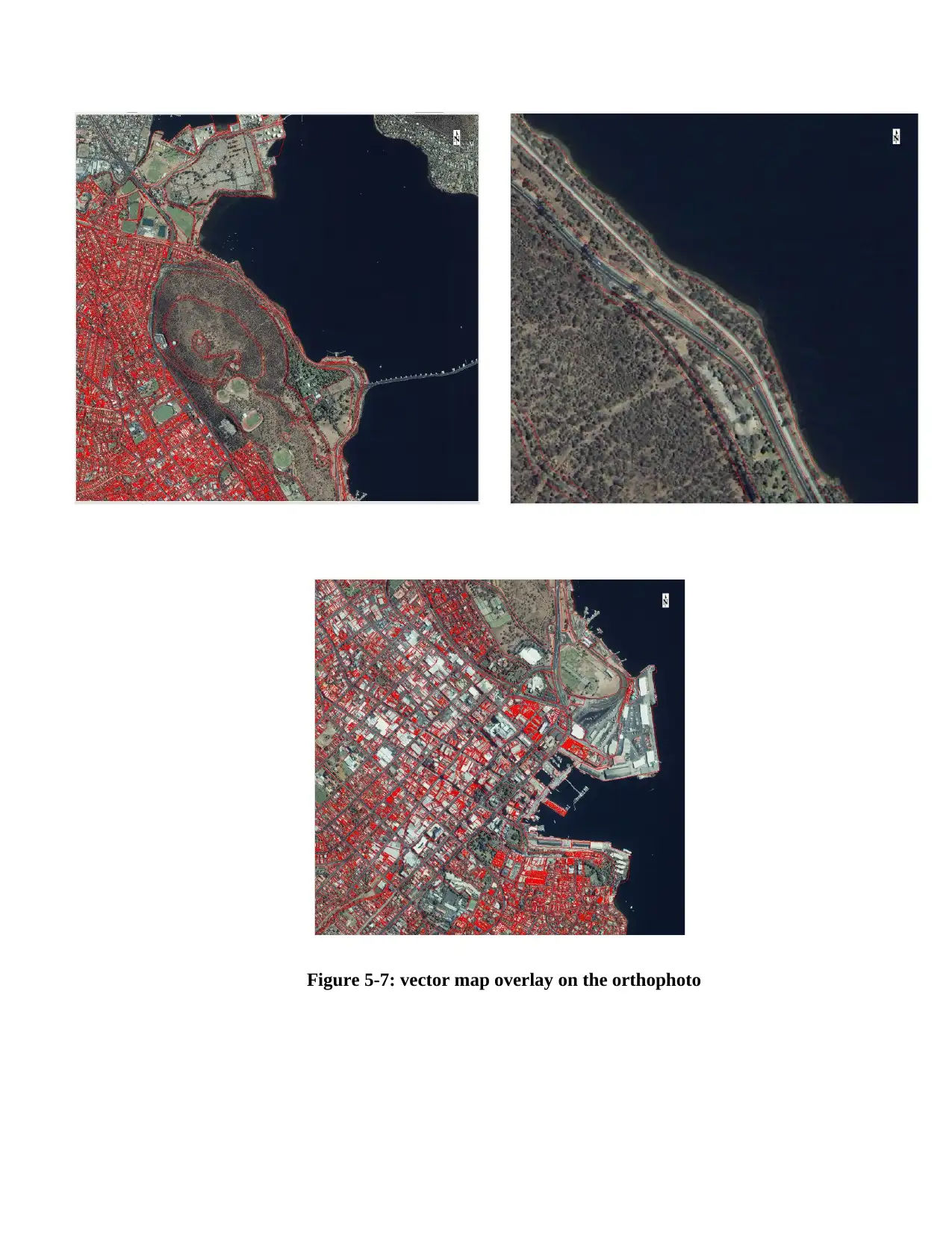
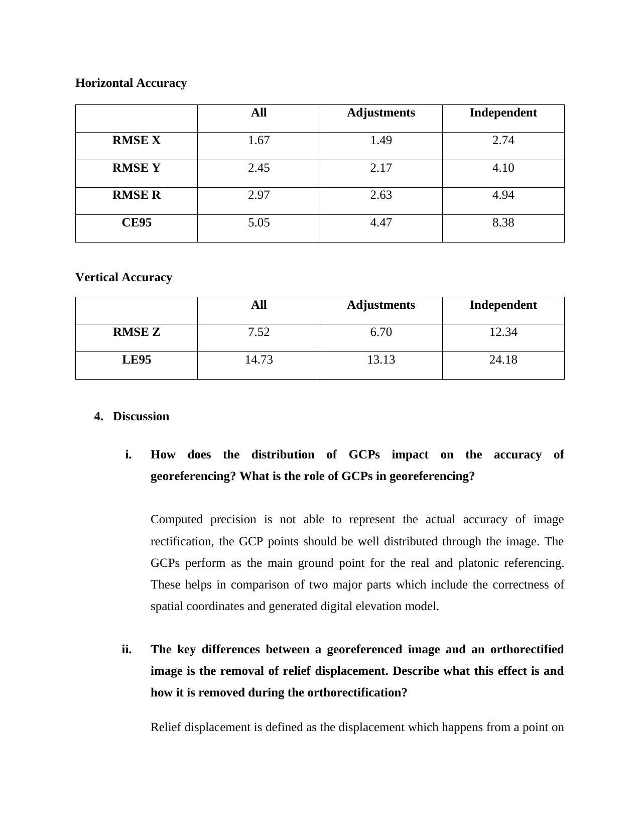
Practical Assignment
AI Summary
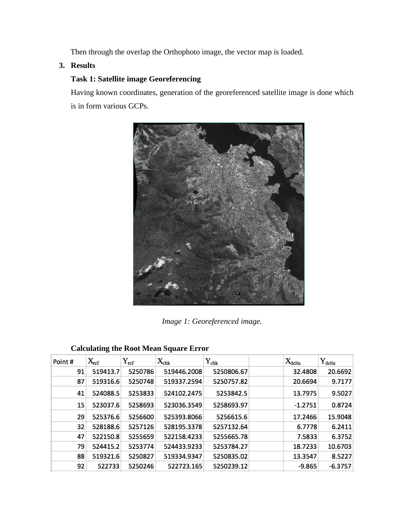
This assignment solution details the process of georeferencing a satellite image, generating a Digital Elevation Model (DEM) from stereo images, and orthorectifying the image using ENVI 5.4. The methodology includes selecting ground control points (GCPs), reducing parallax errors, and assessing accuracy through Root Mean Square Error (RMSE) calculations. The results showcase georeferenced images, DEMs, and orthorectified images with overlaid vector maps. The discussion covers the impact of GCP distribution on accuracy, the differences between georeferenced and orthorectified images, and the calculation of maximum radial error. The conclusion highlights the successful georeferencing and orthorectification process, emphasizing the RMSE values achieved.

Imaging the Environment
Assignment 4
Image Georeferencing and Orthorectification
Assignment 4
Image Georeferencing and Orthorectification
Paraphrase This Document
Need a fresh take? Get an instant paraphrase of this document with our AI Paraphraser

1. Introduction
Georefferencing a satellite image, Digital Elevation Model (DEM) generation from two
sets of images and orthodefying the DEM generation image can be done using ENVI 5.4.
the activity of georeferenced helps to eliminate titling effect of an image. The purpose of
the georeferencing due to the presence of unsynchronized pixels of the non-
georeferencing aerial images with the ground coordinates on the x, y, and z coordinates.
Failure for the to coincide with ground coordinates and the pixel aerial images become
inconsequential because it fails to coordinate with the GPS points. The process of
removing the displacement relief, the optical distortion from the sensor and digital image
geometric perspective is known as orthorectification. Moreover, the process of overlaying
existing vector maps allows for the assessment of the orthorectification accuracy.
2. Method
Task 1: Geoferencing the satellite image
In order to set out the IKONOS window, one navigates through isprs-ikonos-dataset-
hobart file and the two selected files which includes the po_162779_metadata.txt and
po_162780_metadata.txt. After that, Registration: Image to Map is selected from
Geometric Correction > Registration is selected from the toolbox pane. On the two
images, each of the band is selected in order to respond to the RGB layers for the images.
The setting for the image used to map registration window and also the projection
parameters are the UTM zone 55 South, WGS-84 and all pixels at 1 meter. Selection of
the Ground Control Point Selection and that of the GCP file is made on each image. At
this point, the transformation model is made to be more accurate through reduction of
RMS errors. The elevation of the polynomial degree is done to 3 degrees while GCPs
deactivation using RMSE is done to achieve a range of less than a single pixel. The
assessment of lastly done to achieve the accuracy of the georeferenced image. To achieve
the accuracy, 10 GPC points are chosen and the ground coordinates from the already
georeferenced image ar5e maintained.

Calculating the Root Mean Square Error
Calculating the error in X and Y / points.
Mean Error of X and Y=;
Root Mean Square Error for X and Y is equal to;
RMSE combination,
Task 2: Generating DEM from stereo images.
The process of generating a DEM Extraction Wizard: window includes loading of 2
stereo images from a datapacks. Then the loading of the GCPs is done, tying of the points
is generated through adjustment of the points, the search window and moving the window
with minimum correlation of 50, 101, 7 and 57 correspondingly. Reduction of the
parallax error is done to less than 1 pixel, through deleting of the tie which has error. All
through, the points are done such that they are scattered on the entire area of the map.
Afore the generation of the DEM, alteration of the Terrain Relief is done to Moderate and
Terrain Detail to Level 4. This help to generate a high resolution image. In order to
produce an image which has exact colours, the option of utilizing 3D SurfaceView
window whereby RGB lagers of the image are allocated consequently.
Task 3: Orthorectification
When generating the RPC Orthorectification Workflow window, cohortion of the DEM
algorithm as well as GCP_Hobart file is first done. The process of deleting GCP points
with high errors is done to enhance the filtering. Through this action, the horizontal
accuracy to less than 3 meters. After that, generation of the 10 points is done
independently. This helps to measure the accurateness of the image orthorectification.
⊘ This is a preview!⊘
Do you want full access?
Subscribe today to unlock all pages.

Trusted by 1+ million students worldwide

Then through the overlap the Orthophoto image, the vector map is loaded.
3. Results
Task 1: Satellite image Georeferencing
Having known coordinates, generation of the georeferenced satellite image is done which
is in form various GCPs.
Image 1: Georeferenced image.
Calculating the Root Mean Square Error
3. Results
Task 1: Satellite image Georeferencing
Having known coordinates, generation of the georeferenced satellite image is done which
is in form various GCPs.
Image 1: Georeferenced image.
Calculating the Root Mean Square Error
Paraphrase This Document
Need a fresh take? Get an instant paraphrase of this document with our AI Paraphraser

Table 1: Root Mean Square Error
MEx MEy RMSEx RMSEy RMSEp
11.94933 8.21004 11.94933 8.21004 17.13578657
Table 2: RMSE
Task 2: Generation of DEM from stereo images.
Tie points are used to generate the DEM image. This is achieved by ensuring the tie
points with high precision are enough to generate DEM.
Image 2: Digital Elevation Model (DEM)

Image 3: 3D Surface View, true colour image
Task 3: Orthorectification
The orthorectification is carried out to eradicate the relief displacement effect.
Image 4:
Orthorectified
image with
vector map
Task 3: Orthorectification
The orthorectification is carried out to eradicate the relief displacement effect.
Image 4:
Orthorectified
image with
vector map
⊘ This is a preview!⊘
Do you want full access?
Subscribe today to unlock all pages.

Trusted by 1+ million students worldwide

Figure 5-7: vector map overlay on the orthophoto
Paraphrase This Document
Need a fresh take? Get an instant paraphrase of this document with our AI Paraphraser

Horizontal Accuracy
All Adjustments Independent
RMSE X 1.67 1.49 2.74
RMSE Y 2.45 2.17 4.10
RMSE R 2.97 2.63 4.94
CE95 5.05 4.47 8.38
Vertical Accuracy
All Adjustments Independent
RMSE Z 7.52 6.70 12.34
LE95 14.73 13.13 24.18
4. Discussion
i. How does the distribution of GCPs impact on the accuracy of
georeferencing? What is the role of GCPs in georeferencing?
Computed precision is not able to represent the actual accuracy of image
rectification, the GCP points should be well distributed through the image. The
GCPs perform as the main ground point for the real and platonic referencing.
These helps in comparison of two major parts which include the correctness of
spatial coordinates and generated digital elevation model.
ii. The key differences between a georeferenced image and an orthorectified
image is the removal of relief displacement. Describe what this effect is and
how it is removed during the orthorectification?
Relief displacement is defined as the displacement which happens from a point on
All Adjustments Independent
RMSE X 1.67 1.49 2.74
RMSE Y 2.45 2.17 4.10
RMSE R 2.97 2.63 4.94
CE95 5.05 4.47 8.38
Vertical Accuracy
All Adjustments Independent
RMSE Z 7.52 6.70 12.34
LE95 14.73 13.13 24.18
4. Discussion
i. How does the distribution of GCPs impact on the accuracy of
georeferencing? What is the role of GCPs in georeferencing?
Computed precision is not able to represent the actual accuracy of image
rectification, the GCP points should be well distributed through the image. The
GCPs perform as the main ground point for the real and platonic referencing.
These helps in comparison of two major parts which include the correctness of
spatial coordinates and generated digital elevation model.
ii. The key differences between a georeferenced image and an orthorectified
image is the removal of relief displacement. Describe what this effect is and
how it is removed during the orthorectification?
Relief displacement is defined as the displacement which happens from a point on

a photographed image which results from the height on ground. The
orthorectification process is used to correct the relief displacement. This is
achieved through getting the height of each image pixel through DTM or DSM.
This process is achieved through reducing the horizontal accurateness to less than
3 meters for every image pixel and interpolation of the z-values which is derived
from DSM. The project of the Cartesian plane coordinates to the plane of image is
done through georeferencing, transformation and later assigning of the gray value
to pixel in the orthophoto.
iii. Assume an accurateness of 15m for the DEM and 1 degree field of view for
the IKONOS image, what is the maximum radial error of the orthorectified
image?
Extreme radial error(r) = tan (1) x 15 = 23.36
5. Conclusion
This report represents a georeferenced settilite image through the use of ENVI 5.4. the
image was generated using Digital Elevated Model (DEM) and later orthorectifying the
image using DEM. The The root mean square error (RMSE) calculation on the
georeferenced image was based on the X and Y, which was assumed to be 11.95 and 8.21
singly and a joint RMSE of 17.14.
⊘ This is a preview!⊘
Do you want full access?
Subscribe today to unlock all pages.

Trusted by 1+ million students worldwide
1 out of 9
Your All-in-One AI-Powered Toolkit for Academic Success.
 +13062052269
info@desklib.com
Available 24*7 on WhatsApp / Email
Unlock your academic potential
Copyright © 2020–2025 A2Z Services. All Rights Reserved. Developed and managed by ZUCOL.
