IMAT5205 - Database Project: Use Case Realization and UML Diagrams
VerifiedAdded on 2022/09/05
|13
|2182
|25
Project
AI Summary
This assignment, part of the IMAT5205 database course, showcases the use case realization for a world wide tour management system. It utilizes the Unified Modeling Language (UML) to create structural and behavioral diagrams, including an analysis class diagram, a communication diagram, and a sequence diagram. The class diagram illustrates the classes and methods needed for tasks like recording new tours, while the communication and sequence diagrams depict the interactions between system components and actors. The project also evaluates the use of CASE tools, specifically Enterprise Architect, in software development, highlighting their benefits in terms of automation, efficiency, and UML support. The analysis includes how CASE tools aid analysts in design, code generation, and maintenance, as well as their support for UML modeling and object-oriented languages. The project concludes by referencing relevant literature on UML, CASE tools, and software engineering principles.

Running head: IMAT5205 - DATABASE
IMAT5205 – DATABASE
Name of the Student
Name of the University
Author Note
IMAT5205 – DATABASE
Name of the Student
Name of the University
Author Note
Paraphrase This Document
Need a fresh take? Get an instant paraphrase of this document with our AI Paraphraser
1IMAT5205 – DATABASE
Table of Contents
Part 1. Use Case Realization............................................................................................................2
Analysis Class Diagram...............................................................................................................2
Communication Diagram.............................................................................................................4
Part 2. Sequence Diagram................................................................................................................6
Part 3. Evaluation.............................................................................................................................8
Case tools.....................................................................................................................................8
Tasks supported by the tool.........................................................................................................8
Analyst support............................................................................................................................9
UML support...............................................................................................................................9
References......................................................................................................................................11
2IMAT5205 – DATABASE
Part 1. Use Case Realization
The use case record new tour for the word wide tour management system has been
realized using the Unified modelling language (Structural and behavioral diagrams) (Niepostyn
2015). The Diagrams developed are the analysis class diagram, sequence and communication
diagram.
Analysis Class Diagram
Analysis class diagram is an uml structural diagram which shows the required class and
methods for performing any task in the system. A function of a system can be derived as the use
case in uml modelling. The use case requires some resources and methods to perform a single
function (Ben Abdessalem Karaa et al. 2016). The class diagram full fills the functional criteria
of the use case by providing the structural design in software development. It is also known as
the main building block of the object oriented analysis and modelling in software development
life cycle. The class diagram provides support to the coding phase of the development.
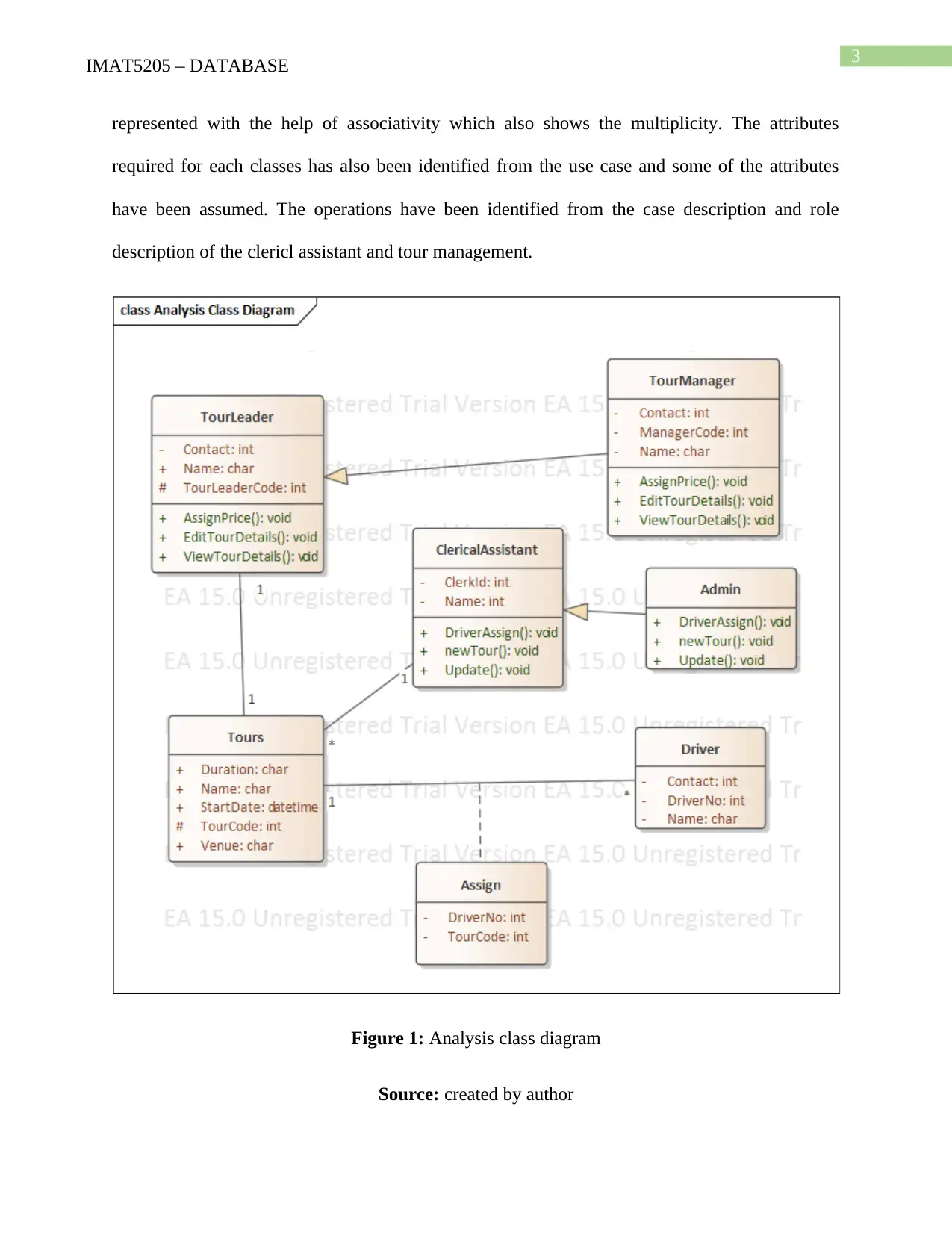
In this scenario of the world wide tour management the use case ‘record ne tour is
analyzed’. The whole process of adding a tour requires the tour details, driver details the person
managing the tour (clerical assistant), and the tour leader who are responsible for managing their
own tour individually. Hence, the classes needed for creating a new record can be identified from
the current use case and the case description. Along with these entities, the tour manager can also
perform the task of tour leader and team administrator can also perform the tasks of clerical
assistant. Hence, the generalization has been used between the respective classes in the diagram.
On other hand, an association class named ‘assign’ is used between the driver and the tour for the
assignment of the drivers to the tour. The rest of the relationship in the classes has been
⊘ This is a preview!⊘
Do you want full access?
Subscribe today to unlock all pages.

Trusted by 1+ million students worldwide
3IMAT5205 – DATABASE
represented with the help of associativity which also shows the multiplicity. The attributes
required for each classes has also been identified from the use case and some of the attributes
have been assumed. The operations have been identified from the case description and role
description of the clericl assistant and tour management.
Figure 1: Analysis class diagram
Source: created by author
Paraphrase This Document
Need a fresh take? Get an instant paraphrase of this document with our AI Paraphraser
4IMAT5205 – DATABASE
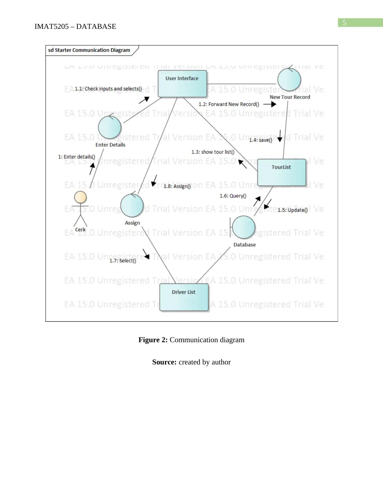
Communication Diagram
A communication diagram is known as the simplified version of the collaboration
diagram in the Unified modelling language. Similar to the sequence diagrams, it shows the
interaction between subsystem boundaries, objects, entities, process and actor in the system. The
interaction is defined with the help of directed messages from on object to another. However, the
interactions are not represented sequentially (Mishra, Mohapatra and Panda 2013). It can be
stated as the combinational diagram of the class diagram, use case diagram and the sequence
diagram. The objects are arranged here freely. The messages are labeled with numbers which
actually represents the sequence of the messages in whole communication.
In the current scenario of the adding new tour record the communication diagram is starts
from the actor clerk. Clerk has the operation of adding the new details in the interface system.
Hence the communication is occurring here between the clerk and the user interface. For
entering the tour leader code the system displays the tour details with the leaders in the interface
and matches with the inputted value by the clerk. The details are retrieved from the database by
the system hence the communication is established between the interface, database and its
entities (Wazlawick 2014). Lastly the driver entity and user interface has the interaction for
accessing driver details and assign them to the newly added tour.
5IMAT5205 – DATABASE
Figure 2: Communication diagram
Source: created by author
Figure 2: Communication diagram
Source: created by author
⊘ This is a preview!⊘
Do you want full access?
Subscribe today to unlock all pages.

Trusted by 1+ million students worldwide
6IMAT5205 – DATABASE
Part 2. Sequence Diagram
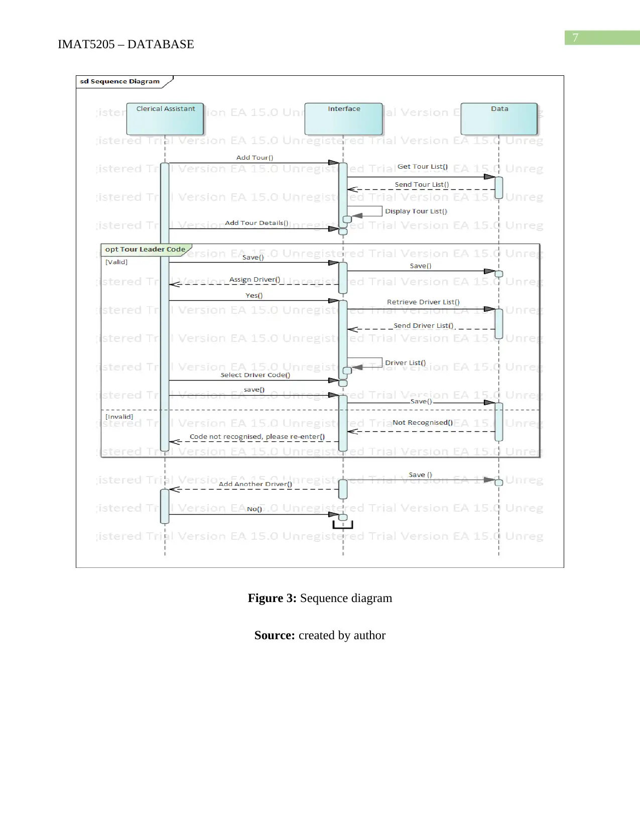
Similar to the class diagram, Sequence diagram can also be mapped from the cases of a
system. The main difference between the diagrams is that class diagram is a structural uml
modelling and sequence diagram is behavioral modelling. Sequence diagram basically represents
the sequences of the interactions between the objects, subsystem and actors over a period of time
in chronological model (Shirole and Kumar 2013). The sequence are defied using the messages
used for the interaction. It provides the logical view system’s activity. It is also stated as event
scenario or event diagrams. It uses the parallel line (vertical), also called lifelines for each object
and process shown with the help of horizontal arrows.
In current scenario, the flow of the recording a new tour is observed to develop a
sequence diagram. It shows the sequences of the messages and their results with
acknowledgement. The Clerk initiates the use case ‘record new tour’ by querying the tour details
in the system interface retrieved from the backend database. Then clerk inputs new tour details
and select a tour leader from the system. This functional requirement has been validate here with
the help of optional path where the clerk inputs an invalid tour leader code and system generates
an error. The clerk can only proceed with the valid tour code leader. Then the new tour is added
in the tour list. Driver is assigned for the new tour which is select by the clerk from the interface
which is retrieved from the driver entity in the database. The process of the use case and
recording anew tour is completed after this sequence of interaction. Then the system saves the
final lists in the database.
Paraphrase This Document
Need a fresh take? Get an instant paraphrase of this document with our AI Paraphraser
7IMAT5205 – DATABASE
Figure 3: Sequence diagram
Source: created by author
Figure 3: Sequence diagram
Source: created by author
8IMAT5205 – DATABASE
Part 3. Evaluation
Case tools
The modeling of the class diagram, sequence and communication diagram has been done
using the enterprise architect software which is a CASE too. CASE tool is Computer Aided
Software Engineering tool which helps in software development efficiently and rapidly
(Bashroush et al. 2017). It is mainly automated with the help of computer tools and software.
The software based on the current technologies such as mobile development, web development,
object oriented software etc. are developed with the help of the CASE tools. In this scenario of
World Wide Tour, the case tools offered the automated modelling of the diagrams. After the
design phase, it can also provide the generation of the source codes of the software which will be
based on the object oriented concepts. The methods, packages, classes, processes and attributes
get automatically generated in the enterprise architect software. It reduces the development time
and cost (Buschle, Johnson and Shahzad 2013). Hence, it can be said that using CASE tools is
effective, less time consuming, less required effort and lest cost consuming approach for
software development.
Tasks supported by the tool
The CASE tools are itself a set of multiple tools which helps in the Software engineering.
In the current modeling of the record new tour for Word Wide Tour, the tool provides Business
modelling and graphical modelling for example the class development, object modelling etc. are
the main models. It also provides better validation as most of the process is automated. In case of
the generalization the methods are automatically extracted from the main tour leader class to the
tour manager class and clerical assistant class to team administrator class (Roth et al. 2013). The
tool also provides the project management, complexity management correctness of the program,
⊘ This is a preview!⊘
Do you want full access?
Subscribe today to unlock all pages.

Trusted by 1+ million students worldwide
9IMAT5205 – DATABASE
performance and may other quality attributes of a software. Along with that the designing is
already present for omission of the errors. The process is automated and the source codes are
designed to be reusable. Hence, there is less chance of complexity error and congestion of the
codes.
Analyst support
A software analyst has the job of analyzing the process and functionality of the system
for the design phase. The case tool is highly supportive for the analyst in terms of design, code,
implementation and maintenance of a system. The case tools are not limited to only one phase in
Software development life cycle (Nowakowski et al. 2013). It uses the toolkits, object centered
language, integration of the code blocks, test case generation and reverse engineering type of
features to perform a testing of the software by the analyst. The Tool also provides the real life
environment for the development. The normal language processing also supports the analyst in
developing the use cases for the system. Late the use cases help in identifying the required
classes, methods and the flow of functions which helps in the development of the behavioral
diagrams of the software.
UML support
UML (Unified modeling language) is a modelling technique for the software
development where the different requirements of the system are modelled and documented in the
form of UML diagrams. It helps the software engineers and system analyst by providing a tool
for the development using a standard notation. The UML is used very widely, hence; the notation
used have become the standard tool in all over the world (Petre 2013). The UML supports the
object oriented languages for modeling which is also the widely used language and platform for
the software development. The risks identified in the analysis phase of the software development
Paraphrase This Document
Need a fresh take? Get an instant paraphrase of this document with our AI Paraphraser
10IMAT5205 – DATABASE
are removable in the designing phase by the use of the UML tools. The structural and behavioral
aspects of UML provide the different angle of inspection and modelling of a software design. It
is also very understandable and readable for the coders. It divides the goal of the system into
multiple objectives which reduces the boundary of the risks and error detection along with the
complexity of the system.
11IMAT5205 – DATABASE
References
Bashroush, R., Garba, M., Rabiser, R., Groher, I. and Botterweck, G., 2017. Case tool support
for variability management in software product lines. ACM Computing Surveys (CSUR), 50(1),
p.14.
Ben Abdessalem Karaa, W., Ben Azzouz, Z., Singh, A., Dey, N., S. Ashour, A. and Ben
Ghazala, H., 2016. Automatic builder of class diagram (ABCD): an application of UML
generation from functional requirements. Software: Practice and Experience, 46(11), pp.1443-
1458.
Buschle, M., Johnson, P. and Shahzad, K., 2013. The enterprise architecture analysis tool–
support for the predictive, probabilistic architecture modeling framework.
Mishra, A., Mohapatra, D.P. and Panda, S., 2013, February. Dynamic slicing of UML
communication diagram. In 2013 3rd IEEE International Advance Computing Conference
(IACC) (pp. 1394-1399). IEEE.
Niepostyn, S.J., 2015. The Sufficient Criteria For Consistent Modelling Of The Use Case
Realization Diagrams With A New Functional-Structure-Behaviour UML Diagram. Przegląd
Elektrotechniczny Sigma NOT nr 21, pp.31-35.
Nowakowski, W., Smialek, M., Ambroziewicz, A. and Straszak, T., 2013. Requirements-level
language and tools for capturing software system essence. Comput. Sci. Inf. Syst., 10(4),
pp.1499-1524.
Petre, M., 2013, May. UML in practice. In 2013 35th International Conference on Software
Engineering (ICSE) (pp. 722-731). IEEE.
⊘ This is a preview!⊘
Do you want full access?
Subscribe today to unlock all pages.

Trusted by 1+ million students worldwide
1 out of 13
Related Documents
Your All-in-One AI-Powered Toolkit for Academic Success.
+13062052269
info@desklib.com
Available 24*7 on WhatsApp / Email
![[object Object]](/_next/static/media/star-bottom.7253800d.svg)
Unlock your academic potential
Copyright © 2020–2025 A2Z Services. All Rights Reserved. Developed and managed by ZUCOL.


