The Assignment on Impact of Jet Introduction
VerifiedAdded on 2022/08/21
|7
|1206
|22
AI Summary
Contribute Materials
Your contribution can guide someone’s learning journey. Share your
documents today.
Impact of jet
Introduction
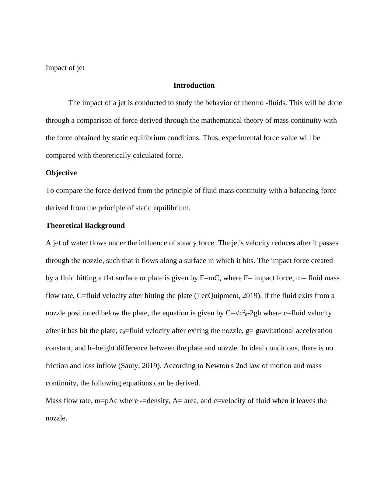
The impact of a jet is conducted to study the behavior of thermo -fluids. This will be done
through a comparison of force derived through the mathematical theory of mass continuity with
the force obtained by static equilibrium conditions. Thus, experimental force value will be
compared with theoretically calculated force.
Objective
To compare the force derived from the principle of fluid mass continuity with a balancing force
derived from the principle of static equilibrium.
Theoretical Background
A jet of water flows under the influence of steady force. The jet's velocity reduces after it passes
through the nozzle, such that it flows along a surface in which it hits. The impact force created
by a fluid hitting a flat surface or plate is given by F=mC, where F= impact force, m= fluid mass
flow rate, C=fluid velocity after hitting the plate (TecQuipment, 2019). If the fluid exits from a
nozzle positioned below the plate, the equation is given by C=√c20-2gh where c=fluid velocity
after it has hit the plate, c0=fluid velocity after exiting the nozzle, g= gravitational acceleration
constant, and h=height difference between the plate and nozzle. In ideal conditions, there is no
friction and loss inflow (Sauty, 2019). According to Newton's 2nd law of motion and mass
continuity, the following equations can be derived.
Mass flow rate, m=pAc where -=density, A= area, and c=velocity of fluid when it leaves the
nozzle.
Secure Best Marks with AI Grader
Need help grading? Try our AI Grader for instant feedback on your assignments.
Final velocity, v=√(c2-2gh) where c=initial fluid velocity, g=9.81m/sec2 and =0.035m.Force
from mass continuity =mass flow rate x final velocity: F=mv
In order to satisfy the condition of static equilibrium, the force on the other end F=4gx where
g=9.81m/s2 and x= distance on measuring scale (TecQuipment,2019)
Procedure
The test plate was connected to the weigh beam assembly with a jockey weight and
nozzle adjusted to face the plate surface. A drain tube was connected to the base of the cylinder
to direct water back to the hydraulic bench. The apparatus was leveled and the weigh beam
assembly set to zero. Water was pumped into the cylinder and steady flow was obtained. The
flow from the hydraulic bench was set to a maximum, and jet force measured and recorded. The
flow rate was adjusted in several increments, with a recording of jet force on the plate being
done. The experimental results were compared with the theoretical results
As the mass is increased, time readings were recorded. Hence flow rate ( Q) was calculated using
the formula: Q= Volume
Time
Results and Discussions
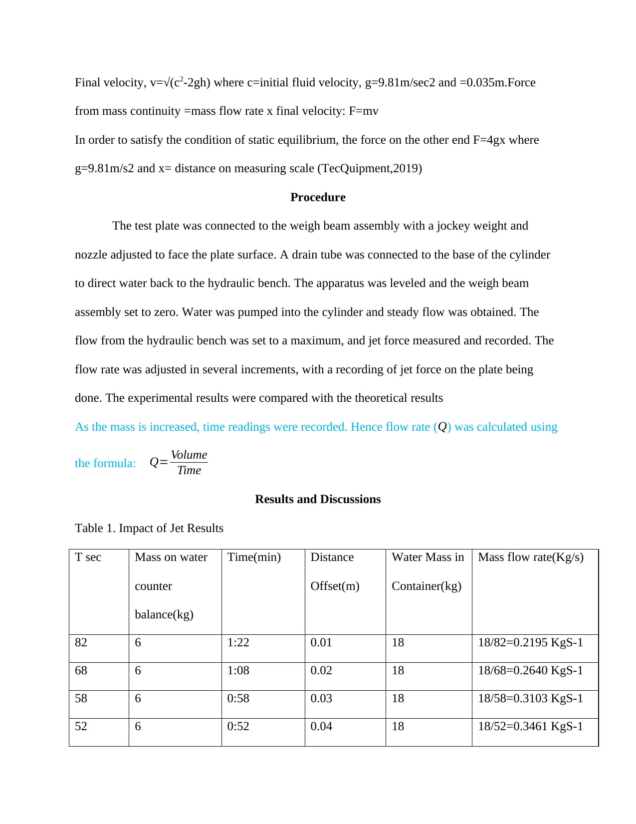
Table 1. Impact of Jet Results
T sec Mass on water
counter
balance(kg)
Time(min) Distance
Offset(m)
Water Mass in
Container(kg)
Mass flow rate(Kg/s)
82 6 1:22 0.01 18 18/82=0.2195 KgS-1
68 6 1:08 0.02 18 18/68=0.2640 KgS-1
58 6 0:58 0.03 18 18/58=0.3103 KgS-1
52 6 0:52 0.04 18 18/52=0.3461 KgS-1
48 6 0:48 0.05 18 18/48=0.375 KgS-1
44 6 0:44 0.06 18 18/44=0.4091 KgS-1
41 6 0:41 0.07 18 18/41=0.4390 KgS-1
65 8 1:05 0.05 24 24/65=0.3608 KgS-1
59 8 0:59 0.05 24 24/59=0.4068 KgS-1
120 8 2:00 0.01 24 24/120=0.2 KgS-1
97 8 1:37 0.02 24 24/97=0.2474 KgS-1
82 8 1:37 0.03 24 24/82=0.2927 KgS-1
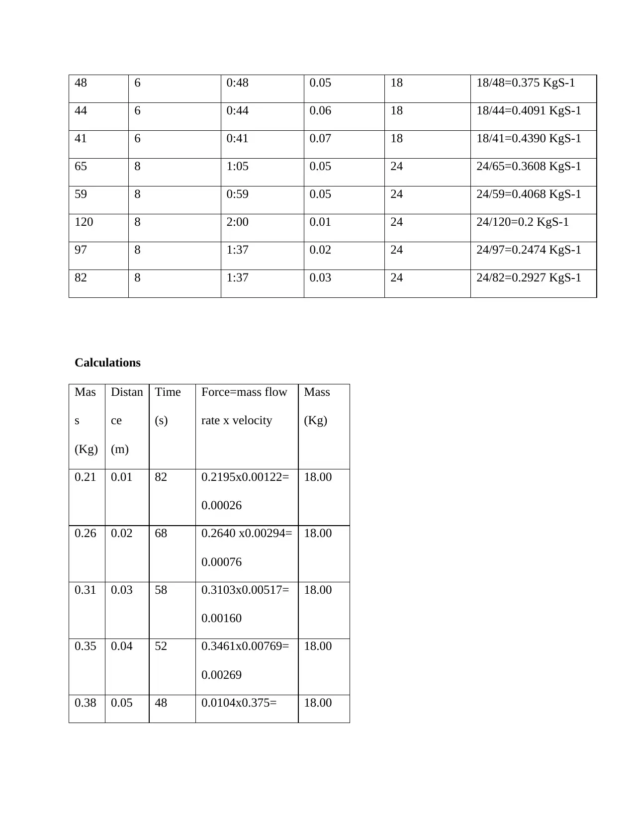
Calculations
Mas
s
(Kg)
Distan
ce
(m)
Time
(s)
Force=mass flow
rate x velocity
Mass
(Kg)
0.21 0.01 82 0.2195x0.00122=
0.00026
18.00
0.26 0.02 68 0.2640 x0.00294=
0.00076
18.00
0.31 0.03 58 0.3103x0.00517=
0.00160
18.00
0.35 0.04 52 0.3461x0.00769=
0.00269
18.00
0.38 0.05 48 0.0104x0.375= 18.00
0.00396
0.41 0.06 44 0136x0.4091=
0.00559
18.00
0.44 0.07 41 0.439x0.0170=
0.00751
18.00
0.37 0.05 65 0.2769 x0.00769=
0.00285
24.00
0.41 0.05 59 0.3050 x0.0084=
0.00347
24.00
0.2 0.01 120 0.150 x0.00083=
0.00017
24.00
0.25 0.2 97 0.1855 x0.00206=
0.00052
24.00
0.25 0.03 97 0.2195 x0.00309=
0.00077
24.00
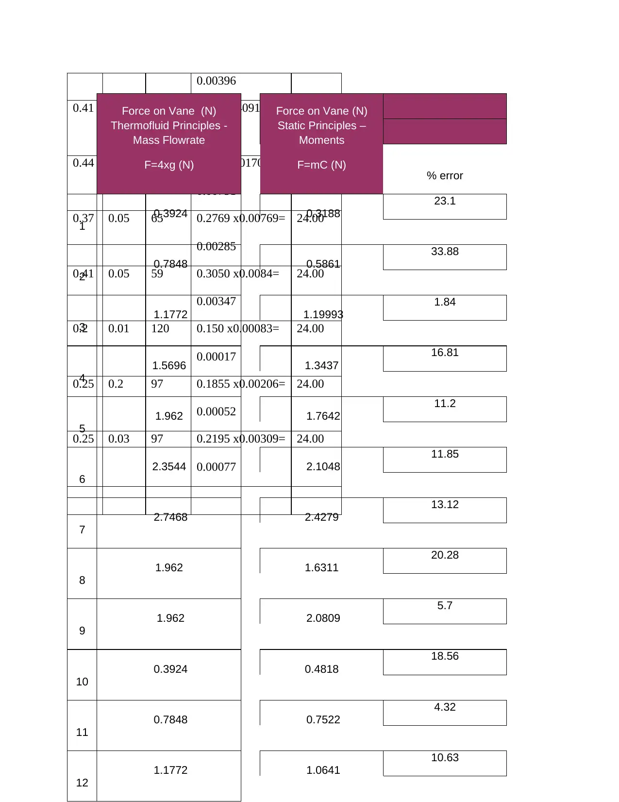
Force on Vane (N)
Thermofluid Principles -
Mass Flowrate
F=4xg (N)
Force on Vane (N)
Static Principles –
Moments
F=mC (N)
%%
% error
1
0.3924 0.3188
23.1
2
0.7848 0.5861
33.88
3
1.1772 1.19993
1.84
4
1.5696 1.3437
16.81
5
1.962 1.7642
11.2
6
2.3544 2.1048
11.85
7
2.7468 2.4279
13.12
8
1.962 1.6311
20.28
9
1.962 2.0809
5.7
10
0.3924 0.4818
18.56
11
0.7848 0.7522
4.32
12
1.1772 1.0641
10.63
Secure Best Marks with AI Grader
Need help grading? Try our AI Grader for instant feedback on your assignments.
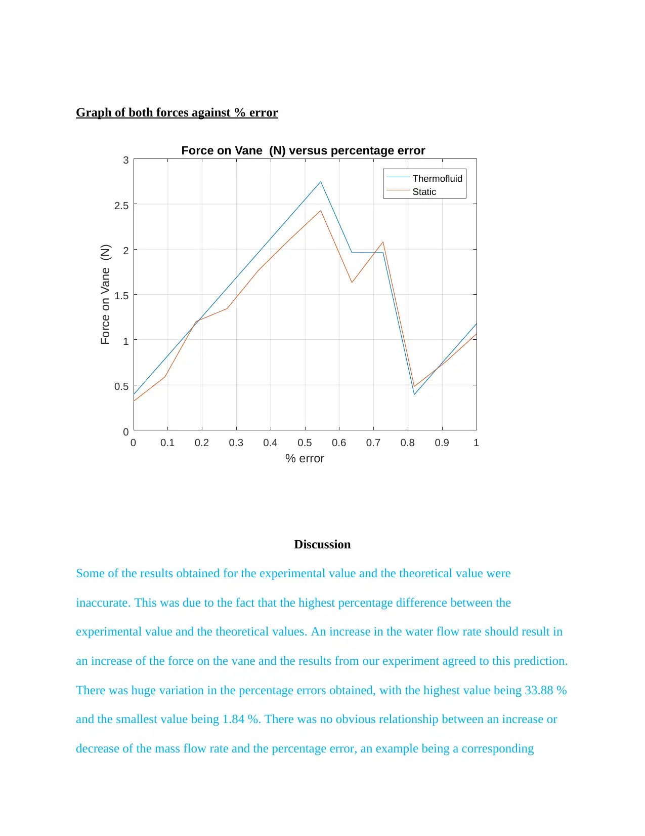
Graph of both forces against % error
0 0.1 0.2 0.3 0.4 0.5 0.6 0.7 0.8 0.9 1
% error
0
0.5
1
1.5
2
2.5
3
Force on Vane (N)
Force on Vane (N) versus percentage error
Thermofluid
Static
Discussion
Some of the results obtained for the experimental value and the theoretical value were
inaccurate. This was due to the fact that the highest percentage difference between the
experimental value and the theoretical values. An increase in the water flow rate should result in
an increase of the force on the vane and the results from our experiment agreed to this prediction.
There was huge variation in the percentage errors obtained, with the highest value being 33.88 %
and the smallest value being 1.84 %. There was no obvious relationship between an increase or
decrease of the mass flow rate and the percentage error, an example being a corresponding
increase of percentage error from a value of 23.1 % to 33.88 % for an increase of mass from 0.21
kg to 0.26 kg. However an increase of mass from 0.26 kg to 0.31 kg resulted in a huge decrease
of the percentage error from a value of 33.88 % to 1.84 %.
Several possible reasons may have brought the discrepancies found between the theoretical and
the actual results obtained. These errors include:
On the apparatus, inaccurateness is one of the possible errors.
Water stream velocity might not have been constant. This may have produced differing
values between the theoretical values and the experimental values.
Additionally, the deflection of the angle position of the plane might not have been
positioned at the required angles of 900, 1200 or 1800.
Last but not the least; parallax error may have occurred during the experiment. This can
be avoided by ensuring that the observer’s eyes are perpendicular to the measuring scale
of the apparatus while taking the readings of the water that passes through.
From the graph deduced from the results, it can be seen that the force on the vane against
percentage error for both cases produced similar patterns.
Conclusion
Overall, the objective of the experiment was achieved. The force derived from the
principle of fluid mass continuity was compared with a balancing force derived from the
principle of static equilibrium. The two variables did not much due to experimental errors which
need to be minimized.
Reference List
Sauty, C. (2019). JET simulations, experiments, and theory: Ten years after JETSET. What is
next?
TecQuipment. (2019). Impact of A Jet. Available at: https://www.tecquipment.com/impact-of-a-
jet [Accessed 17 Jan. 2020].
Sauty, C. (2019). JET simulations, experiments, and theory: Ten years after JETSET. What is
next?
TecQuipment. (2019). Impact of A Jet. Available at: https://www.tecquipment.com/impact-of-a-
jet [Accessed 17 Jan. 2020].
1 out of 7
Your All-in-One AI-Powered Toolkit for Academic Success.
+13062052269
info@desklib.com
Available 24*7 on WhatsApp / Email
Unlock your academic potential
© 2024 | Zucol Services PVT LTD | All rights reserved.