Implementation of CMM Technology in Production Industries Report
VerifiedAdded on 2023/04/11
|13
|1920
|260
Report
AI Summary
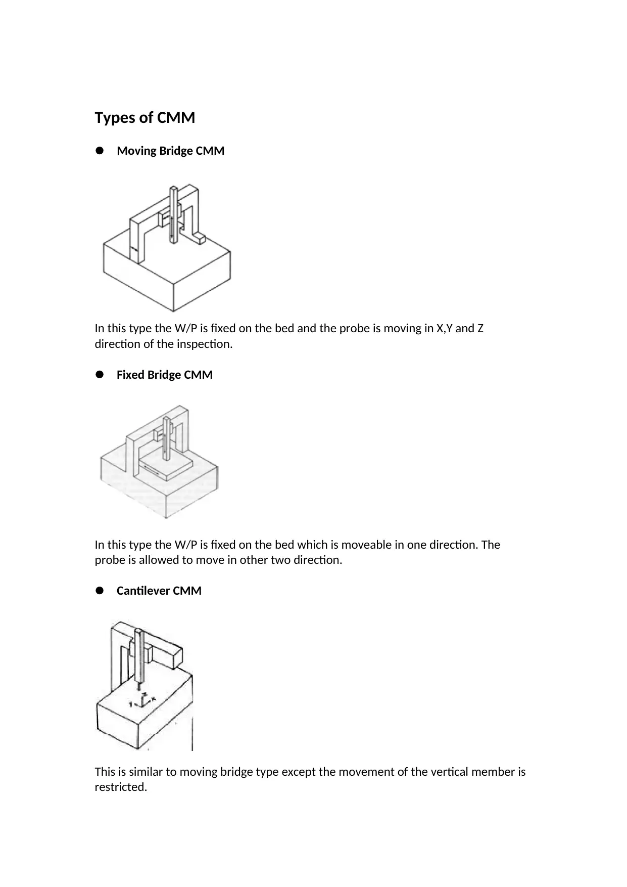
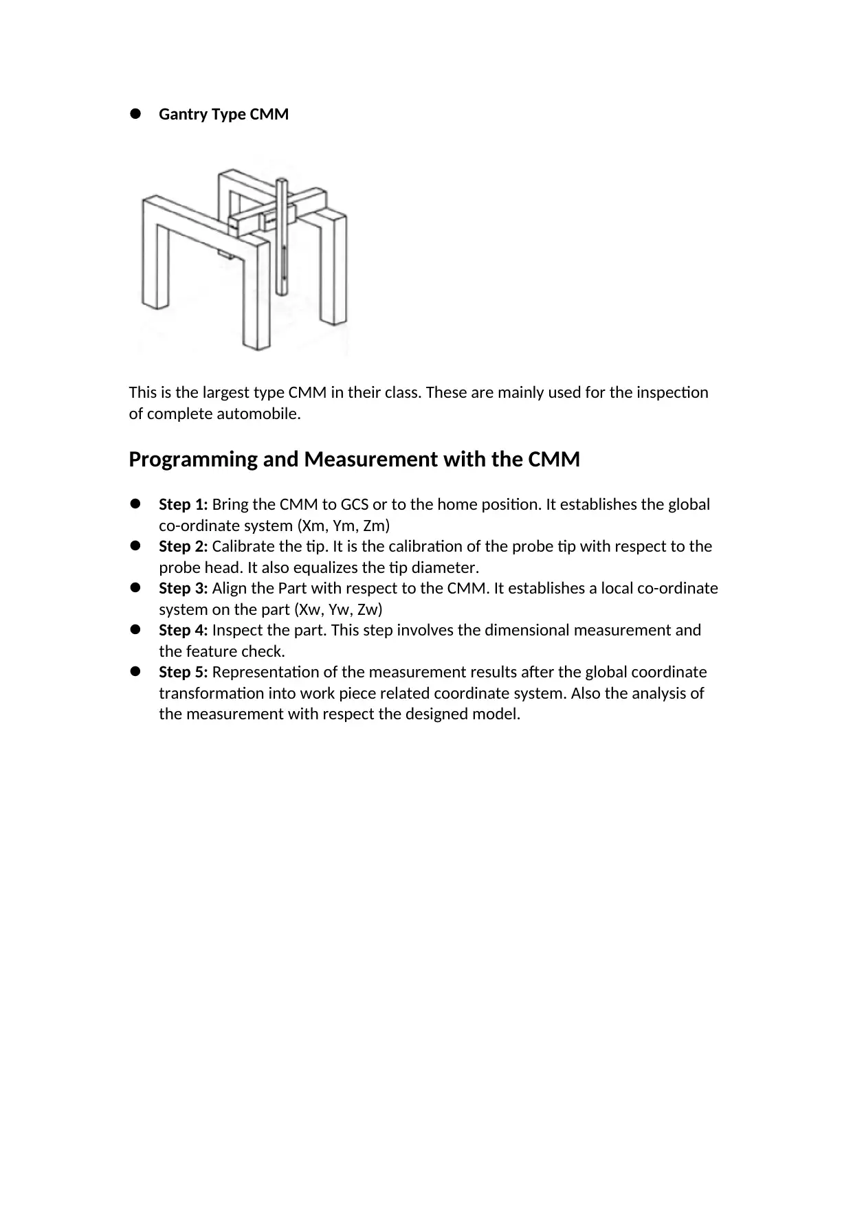
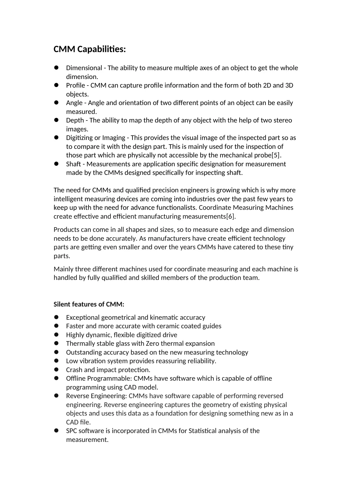
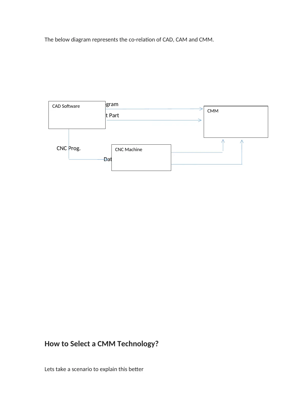
This report delves into the implementation of Coordinate Measuring Machine (CMM) technology within production industries, examining its significance in achieving higher accuracy, speed, and functionality in inspection methodologies. The report begins with an introduction highlighting the importance of CMM in modern manufacturing, emphasizing its role in dimensional inspection and feature checks. It then explores various types of CMMs, including moving bridge, fixed bridge, cantilever, and gantry types, detailing their working principles and capabilities. The report outlines the programming and measurement processes involved with CMMs, including calibration, alignment, and inspection steps. It also covers CMM capabilities such as dimensional measurement, profile capture, angle measurement, and digitizing. Furthermore, the report analyzes the integration of CMMs with Computer-Aided Manufacturing (CAM) to enhance product quality and profitability. A critical aspect of the report is the selection of appropriate CMM technology based on specific scenarios, considering factors like component size, production volume, and tolerance requirements. The report concludes by emphasizing the growing CMM market and recommending a Bridge Type Stationary CMM with specific probe and software configurations for the given scenario, along with references to relevant sources.

PREPARED BY:
IMPLEMENTATION CMM
TECHNOLOGY IN PRODUCTION
INDUSTRIES
IMPLEMENTATION CMM
TECHNOLOGY IN PRODUCTION
INDUSTRIES
Paraphrase This Document
Need a fresh take? Get an instant paraphrase of this document with our AI Paraphraser

Table of Content:
Introduction……………………………………………………………………….Page 3
Types of CMM…………………………………………………………………….Page 4
Programming and Measurement with CMM……………………….Page 5
CMM Capabilities……………………………………………………………….Page 6
CMM in Computer Aided Manufacturing……………………………Page 7
How to Select CMM Technology………………………………………..Page 8
Conclusion…………………………………………………………………………Page 12
Reference………………………………………………………………………….Page 13

Introduction:
Today’s manufacturing industries are giving focus on higher accuracy, speed and
wide functionality for inspection methodology and techniques. With the
development of CNC or computer or numerically controlled machine tools, the
demand has increased for some reasons to support these inspection equipment. To
increase the profitability and reduce the number of rejected parts 100% dimensional
check of the equipment is needed. The Co-ordinate Measuring Machine (CMM) plays
an important role in the measuring and inspection process. CMM can be used as
layout machine before the machining of the parts. Also it can be used for checking
the feature location of the machining parts[1].
Co-ordinate Measuring Machines are mainly developed for measuring and
inspection of 100% dimensional as well as the feature check. Basically, CMM has a
main platform on which the work piece being measured is placed and moved linearly
or rotated. Also the head and shaft of the CMM has a capability to move in linear as
well as angular direction. A probe attached to a head has a capability to move in
linear, vertical and angular movements records all measurements of the work piece.
Coordinate measuring machines are also called measuring or inspection machines.
They have a wide range of capability to record measurement of complex profiles
with high accuracy of (0.25 m) and high speed[2].
Different types of measuring probes are used in CMMs including mechanical, optical,
laser and white light. Depending on the machine and the nature of inspection the
probe position may vary and can be manually operated by the operated or can be
numerically controlled. In addition to the movement in the X, Y and Z axes many
machines allow the probe angle to be controlled and can measure the surface which
are not reachable[3].
These machines can be free standing, hand held or portable.
After this study a brief idea on the following can be established
The working parts of the CMM
The working principle of CMM
The advantage of CMM
How it can increase the profitability of the production unit.
⊘ This is a preview!⊘
Do you want full access?
Subscribe today to unlock all pages.

Trusted by 1+ million students worldwide

Types of CMM
Moving Bridge CMM
In this type the W/P is fixed on the bed and the probe is moving in X,Y and Z
direction of the inspection.
Fixed Bridge CMM
In this type the W/P is fixed on the bed which is moveable in one direction. The
probe is allowed to move in other two direction.
Cantilever CMM
This is similar to moving bridge type except the movement of the vertical member is
restricted.
Paraphrase This Document
Need a fresh take? Get an instant paraphrase of this document with our AI Paraphraser

Gantry Type CMM
This is the largest type CMM in their class. These are mainly used for the inspection
of complete automobile.
Programming and Measurement with the CMM
Step 1: Bring the CMM to GCS or to the home position. It establishes the global
co-ordinate system (Xm, Ym, Zm)
Step 2: Calibrate the tip. It is the calibration of the probe tip with respect to the
probe head. It also equalizes the tip diameter.
Step 3: Align the Part with respect to the CMM. It establishes a local co-ordinate
system on the part (Xw, Yw, Zw)
Step 4: Inspect the part. This step involves the dimensional measurement and
the feature check.
Step 5: Representation of the measurement results after the global coordinate
transformation into work piece related coordinate system. Also the analysis of
the measurement with respect the designed model.

CMM Capabilities:
Dimensional - The ability to measure multiple axes of an object to get the whole
dimension.
Profile - CMM can capture profile information and the form of both 2D and 3D
objects.
Angle - Angle and orientation of two different points of an object can be easily
measured.
Depth - The ability to map the depth of any object with the help of two stereo
images.
Digitizing or Imaging - This provides the visual image of the inspected part so as
to compare it with the design part. This is mainly used for the inspection of
those part which are physically not accessible by the mechanical probe[5].
Shaft - Measurements are application specific designation for measurement
made by the CMMs designed specifically for inspecting shaft.
The need for CMMs and qualified precision engineers is growing which is why more
intelligent measuring devices are coming into industries over the past few years to
keep up with the need for advance functionalists. Coordinate Measuring Machines
create effective and efficient manufacturing measurements[6].
Products can come in all shapes and sizes, so to measure each edge and dimension
needs to be done accurately. As manufacturers have create efficient technology
parts are getting even smaller and over the years CMMs have catered to these tiny
parts.
Mainly three different machines used for coordinate measuring and each machine is
handled by fully qualified and skilled members of the production team.
Silent features of CMM:
Exceptional geometrical and kinematic accuracy
Faster and more accurate with ceramic coated guides
Highly dynamic, flexible digitized drive
Thermally stable glass with Zero thermal expansion
Outstanding accuracy based on the new measuring technology
Low vibration system provides reassuring reliability.
Crash and impact protection.
Offline Programmable: CMMs have software which is capable of offline
programming using CAD model.
Reverse Engineering: CMMs have software capable of performing reversed
engineering. Reverse engineering captures the geometry of existing physical
objects and uses this data as a foundation for designing something new as in a
CAD file.
SPC software is incorporated in CMMs for Statistical analysis of the
measurement.
⊘ This is a preview!⊘
Do you want full access?
Subscribe today to unlock all pages.

Trusted by 1+ million students worldwide

Temperature compensation is incorporated in the CMMs for the change in the
environmental temperature.
The specifications of the machine itself are important for efficient placing the work
piece for the dimensional and feature inspection with high accuracy.
Measuring length is the total distance a probe can move for measuring in the x,
y, or z direction.
Capacity is the maximum size of the object or workpiece that the machine can
accommodate. A CMM must have a capacity sufficient to fit the size of objects
the user needs to measure.
Resolution is the smallest increment that the device can measure to. A higher
resolution denotes a more specific measurement.
Measurement speed is the rate at which a CMM can read positions and take
measurements. It may refer to the imaging speed of the probe, or to the overall
measuring process, which is also a function of control type (CNC being faster
than manual control).
Weight capacity is the maximum or standard weight of the workpiece that the
machine can accommodate. A CMM must have a weight capacity sufficient to
hold the weight of objects the user needs to measure.
CMM in Computer Aided Manufacturing:
The integration of CAM and CMM plays an important role to increase the quality of
the product. Profitability of the production team [5].
Paraphrase This Document
Need a fresh take? Get an instant paraphrase of this document with our AI Paraphraser

The below diagram represents the co-relation of CAD, CAM and CMM.
CNC Program
Data about Part
CNC Prog. Part
Data about part
How to Select a CMM Technology?
Lets take a scenario to explain this better
CAD Software CMM
CNC Machine
CNC Program
Data about Part
CNC Prog. Part
Data about part
How to Select a CMM Technology?
Lets take a scenario to explain this better
CAD Software CMM
CNC Machine

Component Size < 8 m
Number of different components to
inspect
<10
Volume of Production Batch Production(100’s)
Geometrical Complexity of the
component
Prismatic form
Tolerance Required With in 0.1 mm
Inspection Location on Machine On machine
Uses for capture data SPC
Mis details Large CNC milled components
Step 1:
The first question is where to take make the inspection. The parts can be measured
on the machine which require a stationary CMM or a portable CMM can be used.
Since the above scenario is a batch production, a stationary CMM is preferable and
advisable. There are 4 types of Stationary CMM available [4]
Bridge CMM
Cantilever CMM
Horizontal Arm CMM
Gantry CMM
* The functionality and capabilities of the above type of stationary CMM is
described in Page no 2-3
Step 2:
Summing up the capabilities and accuracy of all types of stationary CMM the
following conclusion can be drawn
⊘ This is a preview!⊘
Do you want full access?
Subscribe today to unlock all pages.

Trusted by 1+ million students worldwide

The Horizontal arm CMM is the most flexible but the least accurate CMM
The Cantilever is the most accurate but least flexible CMM
The Bridge and Gantry are moderately accurate and flexible type CMM
The Summary is as below
CMM Type Accuracy Flexibility Best for Inspection
Bridge Moderate Moderate Medium
Component, High
accuracy
Gantry Moderate Moderate Large component
high accuracy
Horizontal Arm Least Most Large component
low accuracy
Cantilever Most Least Small component
high accuracy
As per the scenario the size of the component is within 8 meter. But the number of
components to be inspected is 10. So we need a more flexible CMM considering the
batch production. The tolerance is 0.1 mm which can be considered as moderate
tolerance with respect to the standard of the production industries.
Considering the above factor and the requirement Bridge and Gantry type
sationary CMM are more preferable than the other two type CMM.
Step 3:
it is an important factor where to place the CMM. Basically CMM is the Quality
department child so ideally it should be place in quality shop where the temperature
Paraphrase This Document
Need a fresh take? Get an instant paraphrase of this document with our AI Paraphraser

is maintained to be around 20-25 degree. But considering the size of the inspected
component and size the gantry the CMM can be placed in the shop floor as well.
As per the scenario the components can be considered to medium size compared
with the large components for the production industry but needs high accuracy
inspection.
So the bridge type CMM is the best preferable for the considered scenario.
Step 4:
Selection of accurate probe another vital factor. As per the above scenario all the
parts are CNC Milled components we can use two types of Probe
Touch Trigger Probe
Analog Scanning Probe Touch
These probe consists of probe and converts the electrical signal to analog signal
while doing the inspection. Both of these give accurate result.
Step 5:
Implementing a Robust SpC software with the CMM. This can decrease the
inspection cost, increase the inspection quality as well as improve the final product
quality [9].
Conclusion:
The CMM Market is growing exponentially. The below figure represented the
market growth of CMM [8].

Growth is at 8.00% CGRA
Considering the given scenario we need a Bridge Type Stationary CMM, with Touch
Trigger Probe/analog scanning probe with SPC software that is compatible with the
CMM.
References:
1. Co-ordinate Measuring Machine (CMM) (no date) SRM University[online].
Available from http://www.srmuniv.ac.in [26th March 2019]
2.8
billion
USD
4.1 billion
USD
⊘ This is a preview!⊘
Do you want full access?
Subscribe today to unlock all pages.

Trusted by 1+ million students worldwide
1 out of 13
Your All-in-One AI-Powered Toolkit for Academic Success.
+13062052269
info@desklib.com
Available 24*7 on WhatsApp / Email
Unlock your academic potential
Copyright © 2020–2025 A2Z Services. All Rights Reserved. Developed and managed by ZUCOL.