Build Nationwide ISP

Verified

Added on  2023/01/16

|102
|15734
|2
AI Summary
This BSc project focuses on building a nationwide ISP network and addressing the challenges of providing efficient services. It covers topics such as ISP network architecture, connectivity types, and technologies used. The project also includes practical application on OPNET and analysis of different network designs. The project was supervised by Dr. Shikun Zhou.

Contribute Materials

Your contribution can guide someone’s learning journey. Share your documents today.
Document Page
Individual BSc Project
Build Nationwide ISP
By
Rashed Khalid AlMutlaq
800221
COMPUTER NETWORKS BSc
2018/2019
Supervised by
Dr. Shikun Zhou

Secure Best Marks with AI Grader

Need help grading? Try our AI Grader for instant feedback on your assignments.
Document Page
ABSTRACT
ISP gives benefits that address the issues of clients. As indicated by that, ISP's system ought to be
assembled precisely to keep the forswearing of administration however much as could reasonably
be expected and give the administrations in a productive manner. This venture takes a principled
approaches to manage these difficulties. The task starts by exhibiting some foundation data about
ISP organize design utilizing OPNET. The essential arrangement of system configuration,
directing and tending to are clarified quickly. So as to manage prefixes data from client
associations, distinctive procedures are thought about. It additionally talks about the fundamental
sorts of ISP's availability. The innovations and the applications that are utilized in the task are
clarified succinctly. It additionally gives a short data about the Qatar as a nation, where the
undertaking will be connected. This undertaking additionally introduces how the required system
setups are connected for all intents and purposes on OPNET. Six situations of system designs are
made relying upon two primary topologies. The Six situations are assembled utilizing OPNET to
choose the most proficient one to plan and actualize the venture.
Document Page
ACKNOWLEDGEMENT
I might want to thank the accompanying individuals for their help and support. Thank to Dr.
Shikun Zhou my project supervisor, for his advices amid this undertaking. I might want to say
thanks to him for his accommodating direction, energetic provoking and for honorably giving
me his significant time. I give a modest gratitude to all the staff at School of Computing for the
incredible occupation they did in setting me up to get my [Degree category]. I likewise might
want to thank my dearest guardians, family and companions for their perpetual love and
backing.
Document Page
DEDICATION
The dedication of this thesis goes to my beloved parents, brothers, sisters and friends who helped
me in one way or another to make this work a success. They have been so patient to see me
achieving this goal. I also thank Allah for being there for me, protecting me and giving me this
pressures gift of life.

Secure Best Marks with AI Grader

Need help grading? Try our AI Grader for instant feedback on your assignments.
Document Page
Table of Contents
ABSTRACT....................................................................................................................................2
ACKNOWLEDGEMENT.............................................................................................................3
DEDICATION................................................................................................................................4
CHAPTER ONE: INTRODUCTION...........................................................................................8
1.1 Background Information.........................................................................................................8
1.2 Problem Statement.................................................................................................................11
1.3 Objectives................................................................................................................................13
1.3.1 General Objectives...........................................................................................................13
1.3.2 Specific Objectives...........................................................................................................13
1.4 Project Outline........................................................................................................................14
CHAPTER TWO: LITERATURE REVIEW...........................................................................16
2.1 Introduction............................................................................................................................16
2.2 ISP Network Overview...........................................................................................................16
2.3 ISP Network Architecture.....................................................................................................17
1. Interior Gateway protocol layout.....................................................................................17
2. Network Layout.................................................................................................................18
Physical Layout.....................................................................................................................19
Logical Layout.......................................................................................................................20
Document Page
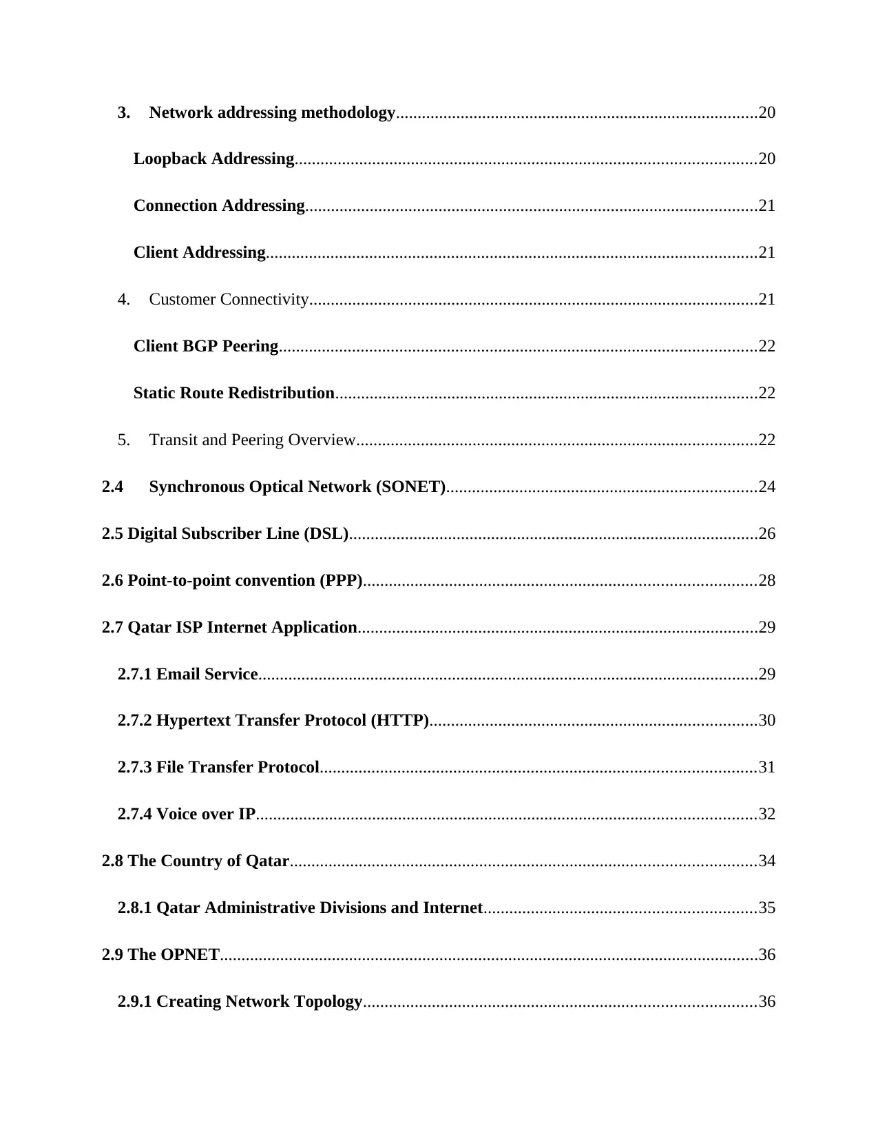
3. Network addressing methodology....................................................................................20
Loopback Addressing...........................................................................................................20
Connection Addressing.........................................................................................................21
Client Addressing..................................................................................................................21
4. Customer Connectivity........................................................................................................21
Client BGP Peering...............................................................................................................22
Static Route Redistribution..................................................................................................22
5. Transit and Peering Overview.............................................................................................22
2.4 Synchronous Optical Network (SONET)........................................................................24
2.5 Digital Subscriber Line (DSL)...............................................................................................26
2.6 Point-to-point convention (PPP)...........................................................................................28
2.7 Qatar ISP Internet Application.............................................................................................29
2.7.1 Email Service....................................................................................................................29
2.7.2 Hypertext Transfer Protocol (HTTP)............................................................................30
2.7.3 File Transfer Protocol.....................................................................................................31
2.7.4 Voice over IP....................................................................................................................32
2.8 The Country of Qatar............................................................................................................34
2.8.1 Qatar Administrative Divisions and Internet...............................................................35
2.9 The OPNET.............................................................................................................................36
2.9.1 Creating Network Topology...........................................................................................36
Document Page
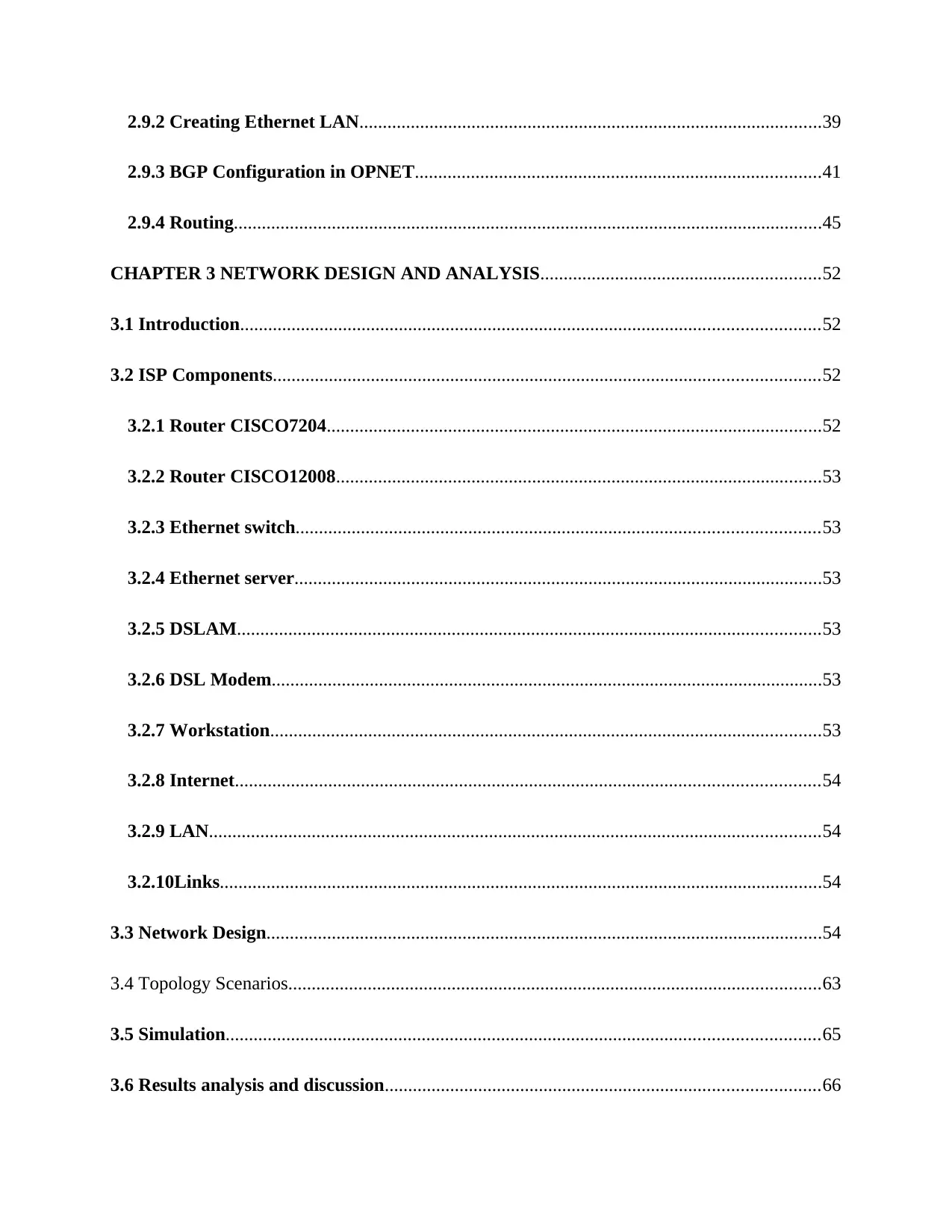
2.9.2 Creating Ethernet LAN...................................................................................................39
2.9.3 BGP Configuration in OPNET.......................................................................................41
2.9.4 Routing..............................................................................................................................45
CHAPTER 3 NETWORK DESIGN AND ANALYSIS............................................................52
3.1 Introduction............................................................................................................................52
3.2 ISP Components.....................................................................................................................52
3.2.1 Router CISCO7204..........................................................................................................52
3.2.2 Router CISCO12008........................................................................................................53
3.2.3 Ethernet switch................................................................................................................53
3.2.4 Ethernet server.................................................................................................................53
3.2.5 DSLAM.............................................................................................................................53
3.2.6 DSL Modem......................................................................................................................53
3.2.7 Workstation......................................................................................................................53
3.2.8 Internet.............................................................................................................................54
3.2.9 LAN...................................................................................................................................54
3.2.10Links.................................................................................................................................54
3.3 Network Design.......................................................................................................................54
3.4 Topology Scenarios..................................................................................................................63
3.5 Simulation...............................................................................................................................65
3.6 Results analysis and discussion.............................................................................................66

Paraphrase This Document

Need a fresh take? Get an instant paraphrase of this document with our AI Paraphraser
Document Page
3.6.1 BGP...................................................................................................................................66
Network convergence............................................................................................................66
3.6.2 Email.................................................................................................................................69
Download and upload...........................................................................................................69
Traffic.....................................................................................................................................70
3.6.3 Ethernet Delay..................................................................................................................71
3.6.4 FTP...................................................................................................................................72
Download and upload response time...................................................................................72
Traffic.....................................................................................................................................73
3.6.5 HTTP.................................................................................................................................75
Object and page response time............................................................................................75
Traffic.....................................................................................................................................76
3.6.6 TCP...................................................................................................................................77
3.6.7 RIP.....................................................................................................................................79
Network Convergence...........................................................................................................79
Traffic.....................................................................................................................................80
3.6.8 Voice.................................................................................................................................81
Jitter.........................................................................................................................................81
Packet Delay..........................................................................................................................82
Traffic.....................................................................................................................................83
Document Page
3.6.9 Objects analysis................................................................................................................85
CHAPTER 4: CONCLUSION AND FUTURE WORK...........................................................87
4.1 Conclusion...............................................................................................................................87
4.2 Limitation and Recommendations........................................................................................89
4.3 Future Work...........................................................................................................................89
Document Page
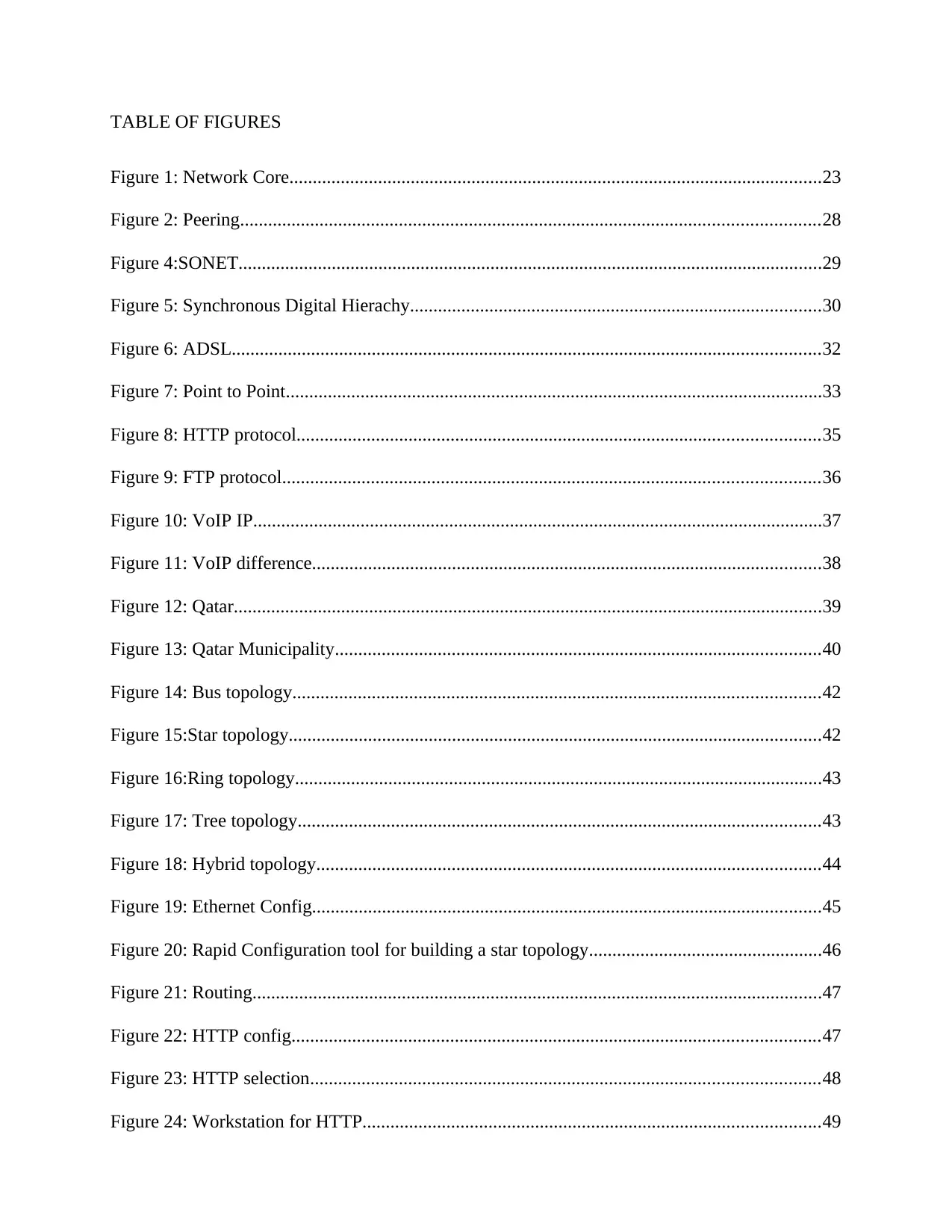
TABLE OF FIGURES
Figure 1: Network Core..................................................................................................................23
Figure 2: Peering............................................................................................................................28
Figure 4:SONET.............................................................................................................................29
Figure 5: Synchronous Digital Hierachy........................................................................................30
Figure 6: ADSL..............................................................................................................................32
Figure 7: Point to Point...................................................................................................................33
Figure 8: HTTP protocol................................................................................................................35
Figure 9: FTP protocol...................................................................................................................36
Figure 10: VoIP IP..........................................................................................................................37
Figure 11: VoIP difference.............................................................................................................38
Figure 12: Qatar..............................................................................................................................39
Figure 13: Qatar Municipality........................................................................................................40
Figure 14: Bus topology.................................................................................................................42
Figure 15:Star topology..................................................................................................................42
Figure 16:Ring topology.................................................................................................................43
Figure 17: Tree topology................................................................................................................43
Figure 18: Hybrid topology............................................................................................................44
Figure 19: Ethernet Config.............................................................................................................45
Figure 20: Rapid Configuration tool for building a star topology..................................................46
Figure 21: Routing..........................................................................................................................47
Figure 22: HTTP config.................................................................................................................47
Figure 23: HTTP selection.............................................................................................................48
Figure 24: Workstation for HTTP..................................................................................................49

Secure Best Marks with AI Grader

Need help grading? Try our AI Grader for instant feedback on your assignments.
Document Page
Figure 25: HTTP server..................................................................................................................49
Figure 26: HTTP server side..........................................................................................................50
Figure 27: Routing..........................................................................................................................50
Figure 28: BGP basic......................................................................................................................51
Figure 29: Running the BGP..........................................................................................................52
Figure 30: The router attributes......................................................................................................53
Figure 31: The R4 attributes...........................................................................................................54
Figure 32: Information for BGP and RIP.......................................................................................54
Figure 33: Exporting routing table.................................................................................................55
Figure 34: RIP Protocol..................................................................................................................56
Figure 35: RIP parameters..............................................................................................................56
Figure 36: OPNET Pallette.............................................................................................................60
Figure 37: OPNET on the map.......................................................................................................60
Figure 38: Subnet centres...............................................................................................................61
Figure 39: LAN connection to subnet............................................................................................62
Figure 40: LAN attributes..............................................................................................................62
Figure 41: DSLAM 2......................................................................................................................63
Figure 42: Connecting user to main routers...................................................................................63
Figure 43: Connection of core router.............................................................................................64
Figure 44: VoIP connection to router.............................................................................................65
Figure 45: Ethernet server..............................................................................................................65
Figure 46: FTP server connection..................................................................................................66
Figure 47: Core router configuration..............................................................................................67
Figure 48: Application connection.................................................................................................67
Document Page
Figure 49: Main connection to subnet............................................................................................68
Figure 50: Topology scenario 1......................................................................................................68
Figure 51: Topology scenario 2......................................................................................................69
Figure 52: BGP network convergence...........................................................................................71
Figure 53: Network convergence for BGP.....................................................................................72
Figure 54: Traffic BGP...................................................................................................................73
Figure 55: BGP traffic swiches......................................................................................................73
Figure 56: Downlod email..............................................................................................................74
Figure 57: Upload email.................................................................................................................75
Figure 58: Email traffic..................................................................................................................76
Figure 59: Traffic mail...................................................................................................................76
Figure 60: Ethernet delay...............................................................................................................77
Figure 61: Download FTP..............................................................................................................78
Figure 62: FTP transfer time..........................................................................................................78
Figure 63: Traffic for FTP..............................................................................................................79
Figure 64.........................................................................................................................................80
Figure 65:HTTP Object and page response time...........................................................................80
Figure 66: HTTP response time.....................................................................................................81
Figure 67: HTTP traffic..................................................................................................................82
Figure 68: Layers of HTTP............................................................................................................82
Figure 69: TCP layers.....................................................................................................................83
Figure 70: TCP layer response time...............................................................................................84
Figure 71: RIP network convergence.............................................................................................85
Figure 72: RIP convergence time rate............................................................................................85
Document Page
Figure 73: RIP traffic......................................................................................................................86
Figure 74: RIP update traffic..........................................................................................................87
Figure 75: Voice jitter....................................................................................................................88
Figure 76: Packet delay..................................................................................................................88
Figure 77: Packet delay in voice....................................................................................................89
Figure 78: Voice traffic..................................................................................................................89
Figure 79: Voice traffic..................................................................................................................90
Figure 80: Object analysis..............................................................................................................91
Figure 81: Object analysis graph....................................................................................................91
LIST OF TABLES
Table 1: Peer tires...........................................................................................................................29
Table 2:Synchronous Digital Hierachy..........................................................................................31
Table 3: VoIP difference................................................................................................................39
Table 4: Application connection....................................................................................................68

Paraphrase This Document

Need a fresh take? Get an instant paraphrase of this document with our AI Paraphraser
Document Page
CHAPTER ONE: INTRODUCTION
1.1 Background Information
The national Internet Service Provider is considered as an organization which normally controls
and provides internet services to a country. For monetary exchange, the national ISP gives users
permission to access the internet a connection called dial up, a connection through the cable
modem, the Digital Subscriber Lines and the Digital Satellite System. Rates for these
administrations rely upon numerous components including set-up costs, use limitations,
information speed, and administrations gave at the client's entryway. National and worldwide
ISPs have diverse territories of inclusion. Some focus on real urban areas in a region while others
spread numerous littler networks just as the bigger ones. Most national ISPs give a Web gateway
webpage where there are an assortment of highlights accessible including email, shopping, and
pursuit. They likewise give lists of destinations and adjustable individual pages, just as
specialized help and bolster administration, (Creating and Configuring Loopback Interfaces
2015).
Across the nation ISP is an essential segment in any nation, and assumes a key job in creating
distinctive divisions, so the previous thirty years have seen expanding building up the framework
of ISP's systems.
The Internet which was initially called the ARPAnet was created as a system between
government explore labs and taking an interest branches of colleges. Different organizations and
associations joined by direct association with the spine, or by courses of action through other
associated organizations, at some point utilizing dialup devices, for example, UUCP. By the late
1980s, a procedure was set up towards open, business utilization of the Internet. The rest of the
confinements were evacuated by 1991, not long after the presentation of the World Wide Web.
Document Page
Amid the 1980s, online specialist organizations, for example, CompuServe and America On Line
started to offer constrained abilities to get to the Internet, for example, email trade, however full
access to the Internet was not promptly accessible to the overall population, (Forouzan 2012).
In 1989, the primary Internet specialist co-ops, organizations offering the open direct access to
the Internet for a month to month expense, were set up in Australia and the United States. In
Brookline, Massachusetts, The World turned into the primary business ISP in the US. Its first
client was served in November 1989. These organizations for the most part offered dial-up
associations, utilizing the open phone system to give last-mile associations with their clients. The
boundaries to passage for dial-up ISPs were low and numerous suppliers developed.
In any case, satellite TV organizations and the phone transporters previously had wired
associations with their clients and could offer Internet associations at a lot higher paces than dial-
up utilizing broadband innovation, for example, link modems and computerized supporter line
(DSL). Accordingly, these organizations regularly turned into the predominant ISPs in their
administration regions, and what was previously a profoundly focused ISP showcase turned out
to be successfully a restraining infrastructure or duopoly in nations with a business broadcast
communications advertise, for example, the United States, (Greene & Smith).
These days, ISP offer web perusing, yet in addition VOIP, IPTV, video conferencing, and so
forth. This conveys a few points of interest to the end clients. They can observe great recordings
whenever of the day. They additionally can supplant their expensive, fixed communication by
less expensive VoIP communication administration. Truth be told, in a large portion of the
significant pieces of the world, the aggressive market between administrators of ISP rebuilds the
ISP administrations with value slice and advancements prompted extraordinary value decreases.
Document Page
Joining video, voice and information administrations has numerous points of interest. In any case,
building ISP with these highlights requires a great deal of contemplations.
In this task, an across the country ISP will be intended to apply in Qatar. It gives an essential
chance to comprehend the foundation of ISP's wired systems. Wired systems will be worked for
this venture to utilize optical fiber, ethernet physical systems, and IP based conventions to help
ISP administrations. So as to set up a proficient and quick access to the web, planning the system
topology and tending to the application execution are critical. In this undertaking, the focus is on
the topology and the execution of the applications which will be actualized. The undertaking is
structured, fabricated, reproduced and streamlined by utilizing OPNET modeler, (Government
2015). OPNET is a well known stage for reproduction, displaying and examination of
correspondence systems.
Qatar comprises of eight municipalities. It is assumed that the ISP will be fabricated utilizing
optical fiber interfaces between the municipalities focuses. The internetworks in each governorate
will be associated with web by rented line (optical lines or ethernet line) for organizations and
ADSL for occupants. Different situations will be worked to examine the ISP foundation, organize
execution applications.
Qatar has a remarkable market from multiple points of view because of the highest per capita
income and high human development in the most recent years just as the inundation of outcasts
into this nation. Qatar more often than not has an all around created media communications
frameworks just as the business has been setting itself up for next influx of the advancements
identifying with the 5G and the IoT and M2M. Improvement of the national broadband system
dependent on the fiber has been well in progress, and the Ooredoo Qatar stays to be the biggest

Secure Best Marks with AI Grader

Need help grading? Try our AI Grader for instant feedback on your assignments.
Document Page
fixed system administrator in the country, (Qatar 2015). Vodafone Corporate Internet Qatar has
likewise been putting resources into the fiber-based system foundation.
Portable segment in this nation has been trying for three noteworthy administrators as they all get
the opportunity to hold nearly a similar piece of the pie and furthermore are exceptionally
focused. The Ooredoo Qatar, just as the Vodafone Qatar both, got the chance to dispatch 4G LTE
administrations in front of the BusinessCom VSAT that saw the decrease in the portable
endorsers in the year 2016 therefore. However, the dispatch of the 4G LTE administrations has
additionally lead to the development in the information incomes for portable administrators just
as growing the information contributions will be the key center territory in pushing ahead,
(Halabi & McPherson).
Qatar has been the host to the developing number of the ICT organizations and has likewise risen
as the innovation startup center for Middle East, making it conceivable because of the emphasis
on the ICT instruction and the administrative condition being helpful for the ICT venture.
Likewise, it has had the capacity to gain heavenly ground in computerized money related
administrations zone with the help from Central Bank of Qatar, (Qatar 2015).
1.2 Problem Statement
What Network Access Providers (ISPs) can and can't do to expand and separate administrations
lies at the center of the discussion over lack of bias in system task. In earlier ages ISPs had
minimal motivator or mechanical ability to go amiss from plain vanilla best endeavors directing
for substance suppliers and from a solitary standard piece rate offered on "everything you can
eat" terms for purchaser access to the Internet. The following age Web has the mechanical ability
and ISPs have the business inspiration to offer "superior to anything best endeavors" directing
Document Page
and premium administrations for both content suppliers and purchasers looking for higher nature
of administration and increasingly solid traffic conveyance.
Web assaults are the reason for harm to data and loss of benefit to numerous people and
organizations on the planet. This could be from robbery of licensed innovation, lost business and
profitability for system blackouts and crisis reaction, and tidy up expenses. There are distinctive
kinds of assaults that incorporate Savage power, Refusal of administration, secondary passage,
speculating secret phrase, sniffer, Trojan steed, infection, and so forth besides, the internet gives
diverse wellsprings of data on security imperfection in equipment and programming. For
instance, assailants can utilize web indexes on the web and rapidly discover data portraying how
to break into different frameworks by misusing known security feeble purposes of the equipment
or programming. Aggressors may likewise utilize robotized apparatuses to inquiry arrange
frameworks, at that point abusing any recognized security shortcomings to pick up unauthorized
access to the system. Notwithstanding, to give guarded measures against these assaults, firewall
and system separating innovation must be actualized to verify the system. Also, the utilization of
security checking that gives a methods by which to affirm that data asset security controls are set
up, compelling, and are not being circumvent is critical. One of the advantages of security
checking is the early recognizable proof of bad behavior or new security vulnerabilities. Early
location and checking can forestall conceivable assaults or limit their effect on PC frameworks .
As needs be, web clients for the most part don't have satisfactory information and skill to
actualize these security foundations. Also, the web clients as a rule don't have the foggiest idea
about that their system frameworks are undermined, this establish some portion of the issue. For
instance, Malware might be dispersed and utilized from multiple points of view, including email
messages, USB gadgets, tainted sites, noxious publicizing, and program vulnerabilities.
Document Page
Anyway the potential exists for bearers, working the real systems used to switch what's more,
course bitstreams, to go past fulfilling various necessities of substance supplier what's more, end
clients. System lack of bias supporters stress that major ISPs have both the fortitude and
motivation to bifurcate the Web into one medium progressively inclined to clog and declining
dependability and one offering prevalent execution and potential upper hands to clients capable
and willing to pay, or associated with an ISP working a noteworthy bitstream transmission
system, for example, AT&T, Verizon and Comcast. Adversaries will not see a present or planned
issue and stress that arrange impartiality necessities legitimize normal bearer guideline of the
Web, an administrative routine up to this time constrained to media communications
administrations working in a less than completely aggressive condition.
Qatar, just like any other country around the world faces the same problems when it comes to ISP
network provision. In order to get done of this problems and inconveniences as discussed above,
hence the core purpose of the project comes in. The system will complete solve if not all, the
problems which have been taken into consideration by the Qatar government.
1.3 Objectives
1.3.1 General Objectives
The general objective of this project is to design, develop and build an OPNET based nationwide
Internet service provider network which is effective and efficient enough to in its application as
well as performance.
1.3.2 Specific Objectives
The most specific objectives of this project is as follows;

Paraphrase This Document

Need a fresh take? Get an instant paraphrase of this document with our AI Paraphraser
Document Page
i. To design and simulate an ISP network to give out a real time graphical outcome.
ii. To test, evaluate and analyze the results which are generated under various application
scenarios.
iii. To make necessary modifications to the configurations in accordance with given
specifications.
1.4 Project Outline
The following is the general outline of the project herein;
Chapter 1: This chapter gives a brief synopsis and introduction of the whole project. The chapter
as well gives the most general information which is related to the project as it also narrows down
to the main projected country which is Qatar. Qatar has been the host to the developing number
of the ICT organizations and has likewise risen as the innovation startup center for Middle East,
making it conceivable because of the emphasis on the ICT instruction and the administrative
condition being helpful for the ICT venture.
Chapter 2: This particular chapter gives a details explanation on the background history of
nationwide design of the ISP, the projects which were done by previous researchers and how is it
related to what i have researched. It also gives a detailed description of the comparison that exists
between the previous researchers projects and the current project, the limitation of the previous
work is also outlined in detail. Aside with the background information of the previous projects,
the chapter also gives an explanation on the physical layout of the network, its overview and the
protocol which are used in the design and development of the project. The internet users who are
Document Page
found and reside in Qatar are also explained in details. The OPNET simulation actions are also
explained here.
Chapter 3: This is where the design of the project is explained and done, the processes which
involves in this designs includes the project components, the physical layouts of the network,
how the OPNET is used in the simulation of the ISP network and the scenarios under which the
simulation can be applied.
Chapter 4: This is the conclusive chapter in this project which concludes the project giving the
results which have been achieved after analysis of the project. The future work which is yet to be
done and invented is also discussed here. The recommendation of the work done and how the
researcher recommends on the project as far as problem solving is concern, is also achieved here.
Document Page
CHAPTER TWO: LITERATURE REVIEW
2.1 Introduction
In this chapter, the operation of the network in terms of its architecture is demonstrated. An
overview of the ISP network is explained. The chapter also explains how various types of
network addressing methods are done, its labelling process is also explained. The methods under
which the ISPs are connected and their respective relations are described. WAN technologies by
SONET and the remote access technologies such as the ADSL are also explained. The chapter
also demonstrates the servers and ISP services. The introduction of OPNET including how to
create the projects, how to create topologies and also how to configure the BGP.
2.2 ISP Network Overview
An examination by Rowe, Wood, Reeves, and Braun detailed, "security specialists have proposed
that Web Access Provider (ISPs) might be in a decent position to cost-viably keep specific kinds
of malignant digital conduct, for example, the activity of botnets on home clients' and
independent ventures' PCs. Like an area security checkpoint that gives a proportion of security to
all houses fanning out the private streets in that, singular Web clients would be vastly improved
ensured if their ISP assumed a bigger security job", (Halabi & McPherson). Allan and Jim
contended that ISPs have an obligation to help shield client PC and information from vindictive
assault. They give an assortment of administrations to client and must utilize best practices to
guarantee security. The job of the network access suppliers is changing and extending, ISP are
change themselves to offer a wide scope of administration to their supporters. They shield
traditions from assault originating from frameworks (instrument) or different clients.

Secure Best Marks with AI Grader

Need help grading? Try our AI Grader for instant feedback on your assignments.
Document Page
Orill stated, "an ISP's situation as passage to the Web expects it to accept a large group of lawful
and moral obligations. The capacity of mysterious clients to openly trade data over the Web
makes lawful duties regarding ISPs to act to the open's advantage. Clients depend on the Web for
individual correspondence, data, and to direct business, giving ISPs an obligation to convey solid
administration and access to the sites and administrations their clients rely upon", (Herps &
Maynes).
2.3 ISP Network Architecture
The part entails the whole network infrastructure for the whole ISP networks. Network design is
primarily divided into the following crucial elements.
• Interior Gateway protocol layout
• Network Layout
• Transit and peering connections
• Network addressing methodology
• Customer connectivity
1. Interior Gateway protocol layout
This is a sort of protocol utilized for exchanging routing data between gateways (normally
switches) inside a self-governing framework (for instance, an arrangement of corporate
neighborhood). This steering data would then be able to be utilized to course arrange layer
protocol like IP, (Kumar & Kumar 2014).
Inside gateways, protocol can be separated into two classifications: remove vector directing
conventions and connection state steering conventions. Explicit instances of IGPs incorporate
Open Most brief Way First (OSPF), Directing Data Convention (Tear), Middle of the road
Document Page
Framework to Transitional Framework (IS-IS) and Upgraded Inside Door Steering Convention.
The most mainstream IGPs utilized in ISP systems are OSPF and IS-IS. IGP conventions can be
set up in multi-region or single-zone condition, (Malik 2012). IGP is utilized in ISP system to
help the foundation of BGP. It gives reachability to next bounce goals for BGP learned prefixes
and BGP peering session. The IGP should compass just the ISP system's switches, not client edge
switches, in any case those switches are overseen by the ISP or not.
2. Network Layout
This is a visual portrayal of system engineering. It maps out the structure of a system with a wide
range of images and line associations. It is the perfect method to share the format of a system on
the grounds that the visual introduction makes it simpler for clients to see how things are
associated. The arrangement of servers as for the firewall and different PCs can influence both
system execution and security, (Oppenheimer 2012). There may even be regions of the system
that are more secure than others. A portion of these zones might be additionally secured with an
extra firewall. This following model delineates how you can adjust the default format of the
system.
Document Page
Figure 1: Network Core
Network layout is divided into Physical and logical layout;
Physical Layout
This is the investigation of the game plan or mapping of the components (links, hubs, and so on.)
of a system, particularly the physical (genuine) and consistent (virtual) interconnections between
hubs. The physical system design is made by the admin to speak to the physical format of the
system. The graphs are the most indispensable documentation expected to catch a wide
assortment of data in your system. Every PC is associated with the center and a link line speaks to
how it is associated, (Oppenheimer 2012). It will assist you with visualizing how much hardware
you will need and show contractual workers or experts what your thought for the system is.

Paraphrase This Document

Need a fresh take? Get an instant paraphrase of this document with our AI Paraphraser
Document Page
Logical Layout
The legitimate Physical design will be utilized to speak to how you organize associations are
utilizing the upper layer of the OSI, and will comprehend your IP tending to. For instance, if a
workstation is never again ready to get to the system, the director will most likely check their
line, check the center point and confirm the association effectively and preclude these
conceivable blunders all the more proficiently. It is the initial step to be taken before setting up
your system, and expected to comprehend and keep up the diverse gadgets, (Raimi 2011). After
you have made your physical system outline, the subsequent stage is make an intelligent system
chart. It's anything but a chart that will be seen effectively by the executives yet is as yet a crucial
report for any organization that has a system. What is the most ideal approach to help other
people pursue your systems? Associations will be the physical system outline. also, its
availability, territories that are not canvassed in the physical chart. With this chart, the IT
individual will have an important reference manage for investigating, preparing new workers and
help outside merchants that may need to comprehend your system, (Ramli 2012). This chart will
show every hub on the system, and speaks to physically how the system fits together.
3. Network addressing methodology
Foundation tending to of ISP are two kinds of tending to loopback addresses and connection
addresses. These are examined in the following segments. You'll at that point get familiar with
client tending to.
Loopback Addressing
It is free of any physical interface while, just the switch is the main gadget in the subnet, allowing
a/32 to be utilized for ideal location. The loopback address that isn't utilized for the RP Any-give
Document Page
ought to be utilized a role as the BGP switch ID. This keeps the likelihood of BGP foundation
flop from repeat BGP switch IDs present in the system, (Raimi 2011).
Connection Addressing
The spine association show is a point-to-point association, just two gadgets in a subnet. The/31
subnet without a system or communicate address underwrite address effectiveness while
arranging join tending to.
Client Addressing
The run of the mill model to oversee client prefixes is to transmit them in BGP and not the IGP.
The outcome is that there is no an incentive to be had by inside conglomerating or apportioning
address space on region premise. There is likewise the extra trouble that client regularly multi-
home or once in a while move and should be rehomed. Keeping up an exacting region tending to
structure can turn into a regulatory issue that isn't upheld by specialized advantages.
4. Customer Connectivity
ISPs utilize two general methods to manage prefix data from client associations. These strategies
are BGP peering with the client and static course executed on the edge switch, at that point
redistributing the prefix data into BGP.
Document Page
Client BGP Peering
Multi-homed Customers or clients who need the capacity to progressively publicize prefixes use
BGP peering. Multi-homed client to various ISPs ought to have an interesting open self-
governing framework number. Be that as it may, if the client is multi-homed to one ISP or isn't
multi-homed and needs the capacity to progressively promote prefixes, two methods are utilized
without remarkable open self-ruling framework, (Rekhter & Li,). These strategies are:
• Generic Customer ASN: The ISP gets single ASN from an allocating expert for it and its
clients.
• Private ASN: to utilize an ASN in the range 64512 to 65535 which are held for private use.
These ASNs is utilized locally, so the ISP should expel the private ASN before sending data of
the open web.
Static Route Redistribution
This technique connected on the ISP edge switch to give client availability and avert overhead for
BGP peering sessions. A static course to the ISP ought to be executed on client switch. At that
point, it redistributed into BGP on the ISP edge switch. At the point when course is embedded
into BGP over redistribution, the starting point is set to inadequate. ISP as a rule redistributes the
courses over a course guide to physically set the beginning to IGP and complete any BGP trait
control, (Sethi & Hnatyshin 2012). Utilizing course maps to channel redistribution may diminish
arrangement blunders.
5. Transit and Peering Overview
This part takes about upstream ISP availability the Internet. There are three essential kinds of
upstream availability:

Secure Best Marks with AI Grader

Need help grading? Try our AI Grader for instant feedback on your assignments.
Document Page
• Transit.
• Peering (open and private)
• ISP levels and peering.
The upstream network subject is identified with political parts of the ISP business, this will be
clarified in the following areas.
Travel Connectivity
It implies that The ISP purchase full network to the web from another ISP. It is mainstream to
little and medium ISP. The clients purchase travel administrations from an ISP which implies that
the clients travel their system to achieve a goal on the web utilizing upstream ISP.
Peering
When any two ISPs have peering between them, it implies that they can achieve one another and
their clients through that association. The term peering alludes to both open and private peering.
Peering in a general sense between two ISPs implies that reachability to that ISP and its
immediate clients is given over that association. In the event that ISP1 and ISP2 start a peering
association, they can achieve one another yet not ISP3 in the event that it's anything but a client
of either ISP1 or ISP2. Basically, peering includes the trading of halfway courses between the
two peering ISPs, (Smith 2014).
Document Page
Figure 2: Peering
The expense of peering is normally not exactly full travel administration, on the grounds that
both ISPs peering hope to offload the traffic going between their clients from their travel joins.
All in all, there are three ISP tires, as appeared table 2.1. The tire 1 suppliers are in 8 Qatar
Municipalities blocks which are Doha, Al Shamal, Umm Salal, Al Khor, Al Daayen, Al Wakrah,
Al Rayyan and Al-Shahaniya.
Document Page
Table 1: Peer tires
2.4 Synchronous Optical Network (SONET)
SONET is an institutionalized convention for fast synchronous exchanging of information
through optical fiber links utilizing Laser or LED. This innovation is broadly utilized IN the ISP's
inside systems. It is likewise utilized in private systems to connect far off areas in a WAN or
MAN. SONET utilizes point-to-point at information connection and system layers to transmit
parcels, (Stallings 2007).
Figure 3:SONET

Paraphrase This Document

Need a fresh take? Get an instant paraphrase of this document with our AI Paraphraser
Document Page
Table 2:Synchronous Digital Hierachy
Parcel over SONET (POS) is assessed to be mainstream since it offers rapid information
transmission, low mistake rates and low inertness. It additionally offers higher speed than ones
utilized by the European E framework and the North American Digital Hierarchy. SONET
multiplex and demultiplex of individual flags progressively productive, (Wisniewski 2001). Be
that as it may, segregating one channel utilizing the European E framework and North American
Digital Hierarchy with plesiochronous frameworks is increasingly mind boggling. Despite the
fact that isolating a 64 kbps channel from a DS1 circuit is basic, isolating a 64 kbps channel from
a DS3 trunk needs de-multiplexing to the DS1 level first.
Document Page
The SONET necessity expresses a four-layer convention stack. The four layers have the
accompanying jobs:
• Photonic layer: decides the physical properties of the optical hardware.
• Section layer: decides the casing design and the difference in edges to optical signs.
• Line layer: decides multiplexing and synchronization onto SONET outlines.
• Path layer: decides start to finish transport.
2.5 Digital Subscriber Line (DSL)
DSL innovation is created to give fast web get to. It is a gathering of advances which are ADSL,
HDSL, SDSL and VDSL. XDSL as a rule alludes to this sit, the X can be substituted by A, H, S,
or V. Just ADSL will be talked about in light of the fact that it will be executed in this venture.
ADSL offers further developed information rate in the download than in the transfer, (Zhang &
Barrell). It explicitly separates the current transmission capacity of the nearby circle unequally to
the houses occupants' client. ADSL isn't proper for business customers since they require a high
bidirectional data transfer capacity.
The transmission capacity that can be taken care of by phone lines contorted link comes to up to
1.1 MHz. In any case, the channel fixed in phone organization office diminishes the transmission
capacity to 4 KHz for voice correspondence. For ADSL, channel is removed to get 1.1 MHz to
help the two information and voice. The data transfer capacity is partitioned into downstream
channel, upstream channel and voice channel, as appeared in figure 4.
Document Page
Endorser can utilize voice channel and information channel in the meantime. The rate of
upstream achieves 1.44 Mbps. Be that as it may, the information rate normally beneath 500 kbps
in light of the commotion in the channel. The rate of downstream achieves 13.4 Mbps.
Figure 4: ADSL
Be that as it may, the downstream rate generally littler than 8 Mbps in light of the commotion in
the channel. So ISP administrations, for example, HTTP or Email is given by the phone systems.
At the phone organization site, an advanced endorser line get to multiplexer (DSLAM) is utilized
rather than ADSL modem. DSLAM put the information in bundles to be sent through the
Internet.
2.6 Point-to-point convention (PPP)
PPP was created by the web building team (IETF) as a standard information interface layer
convention for exchanging diverse system layer conventions through sequential. It is for

Secure Best Marks with AI Grader

Need help grading? Try our AI Grader for instant feedback on your assignments.
Document Page
interfacing clients to a focal office. It is utilized in different WAN advances, for example, simple
lines, computerized rented lines, ISDN, and other.
Figure 5: Point to Point
It offers the administrations beneath:
• Error location.
• Link setup.
• Network layer convention multiplexing.
• Authentication.
• Header pressure.
• Error recognition.
• Link-quality testing.
• Link-choice arrangement.
Document Page
Point-to-point convention has four employable layers:
• The physical layer depends on various worldwide determinations for sequential correspondence,
just as EIA/TIA-232-C, EIA/TIA-422, V.35, and V.24.
• The embodiment of system layer datagrams depends on the standard (HDLC) convention.
• The Link Control Protocol (LCP) is intended for setting up, arranging, verifying, and testing an
information interface association.
• A group of Network Control Protocols (NCPs) is intended for building up and arranging
diverse system layer conventions, similar to IP, IPX, AppleTalk, and DECnet
2.7 Qatar ISP Internet Application
2.7.1 Email Service
Email application is utilized vigorously through web. These days, messages can contains voice,
pictures, information and recordings. Email application is upheld by Simple Mail Transfer
Protocol (SMTP). It is the run of the mill convention for mail exchange through hosts. Electronic
mail tasks start when mail is produced by a client operator program in response to client input.
The created message contains a header which comprises of the email collectors' locations and
extra data, and a body which contains the message, (Zhou2015). These messages are then
arranged in some style and conveyed as contribution to a SMTP sender program that is server's
program on the PC.
The client specialist determined the rundown of mail goals from 822 message headers. At that
point the client specialist indicates the real letter box name of the goal, (Zhou2015). The SMTP
sender sends the messages to the goal have through SMTP exchanges over TCP associations.
When the SMTP sender closes conveyance of a particular message to a particular host, it expels
Document Page
the goal from messages goal list. The message is expelled from the line, after all goals of it are
prepared. The SMTP sender enhances some line procedure. For instance, it sends numerous
messages in a single TCP association, if the messages are set up to send to a similar PC. The
SMTP manages numerous mistakes, for example, inaccessible goal, disappointment of TCP
associations, or out of tasks, (Zhou2015).
2.7.2 Hypertext Transfer Protocol (HTTP)
HTTP considers as one the most critical conventions of the web. It is for exchanging information
proficiently. This information can be plaintext, hypertext, sound, pictures, and so forth
commonly. HTTP is utilized for web perusing between an internet browser, for example, web
pioneer, fire fox and google chrome and a web server. HTTP is viewed as a solid convention
since it utilizes TCP. Each exchange is handled separately so it thinks about a stateless
convention. Normal usage creates new association among customer and server for each
transmission procedure and after that, shuts the association following the transmission is done,
regardless of whether the condition does not organization this balanced connection among
transmission and association periods.
Figure 6: HTTP protocol

Paraphrase This Document

Need a fresh take? Get an instant paraphrase of this document with our AI Paraphraser
Document Page
2.7.3 File Transfer Protocol
A standout amongst the most basic assignments of systems is exchanging records. Be that as it
may, a large portion of documents which are exchanged through the web have an extraordinary
volume. This segment takes about The File Transfer Protocol (FTP) which is the common
convention to exchange documents through web, (Zhou2015).
Record Transfer Protocol (FTP) is the standard TCP/IP for trading documents among frameworks
and customers. In spite of the fact that record exchanging appears to be straightforward, a few
difficulties show up amid document exchanging. For instance, the transmitter and the beneficiary
utilize diverse document frameworks, they utilize distinctive strategies to symbolize content and
information, or they utilize diverse index structures. FTP comprehended all the past difficulties.
Figure 7: FTP protocol
FTP makes two associations among sender and collector. One of the associations is to exchange
information, the other for directions and reactions. Isolating information exchange and directions,
Document Page
FTP become increasingly proficient. A straightforward correspondence rules are utilized by the
control association.
2.7.4 Voice over IP
Web perusing and email administrations need to send and get a little size of parcels over web. Be
that as it may, voices and recordings need a vast size of parcels. Web communication compacts
voice into IP parcels, at that point exchange it over the web. Each parcel's size is in excess of
1500 bytes.
By and large, voice is packed to 8 kbps through applying standard ways. The IP overhead raises
the information rate to 14.8 kbps. The transmission capacity can be decreased to around 6 kbps
by utilizing quiet pressure innovation just when a client is taking. The data transmission for voice
is naturally opened up amid times of quiet, (Zhou2015).
Figure 8: VoIP IP
IP communication doors are utilized to change over Voice flag transformation occurs. One of its
sides is associated with the PSTN or PBX and the other one is associated with an IP switch on the
Document Page
opposite side. IP communication doors are additionally vital for gathering data about client and
telephone number of goal. The portal gathers client data and a goal telephone number. Passage is
arranged in a few pieces of the world utilizing guardians to course the few portals.
Table 3: VoIP difference
2.8 The Country of Qatar
Qatar is one of the Arabic countries which is located in the northern coast of Peninsular and the
western side of Asia. The country is situated in a land whose terrain is made up of arid desert. In
the coast is the capital city of Doha which is also well known for its furturistic skyscrapers and
many other architectures which are ultramodern and ancient Islamic based, this includes the
Museum which is made of limestone of the Islamic Art.
As at 2017, the total population of Qatar was 2.6 millions with only 313,000 registered as Qatar
citizens and around 2.3 millions expatriates. Being the country with the highest per capita income

Secure Best Marks with AI Grader

Need help grading? Try our AI Grader for instant feedback on your assignments.
Document Page
in the whole world, the country is classified by the United Nations Group as the only country
leading in human development and is considered as the most advanced country in the Arab
Emirates, (Qatar 2015).
Figure 9: Qatar
2.8.1 Qatar Administrative Divisions and Internet
From the year 2015, Qatar was divided into now eight mounicipalities, Al Daayen being the
newest municipality which was created under the resolution Number 13, Al Ghuwariyah was
converged with Al Khawr; Al Jumaliyah was converged with Ar Rayyan; Jarayan al Batnah was
part between Ar Rayyan and Al Wakrah; and Mesaieed was converged with Al Wakrah.In 2014,
the western city of Al-Shahaniya split off from Al Rayyan Municipality to frame its own
Document Page
municipality. The above municipalicities are further divided into 98 zonals as referenced to 2015,
This is then divided to blocks and districts as the very lowest divisions, (Qatar 2015).
The diagram below shows the administrative divisions of Qatar.
Figure 10: Qatar Municipality
2.9 The OPNET
OPNET organization was established in 1986 and opened up to the world in 2000. In October
2012, OPNET was obtained by Riverbed Technology. Simulating the execution for a few
frameworks is a basic instrument for any IT proficient. Today, utilizing Simulation to assess the
execution of any framework is critical before interest in costly equipment. Be that as it may,
Document Page
building a reenactment demonstrate is certainly not a fiddling errand. It needs profound
comprehension of reenactment, demonstrating, framework properties, and numerical foundation.
OPNET modeler is the most famous item for system reproduction. It is utilized in instructive and
mechanical segments, (The Global Information Technology Report 2013). A few colleges use
OPNET in training correspondence and PC systems, just as, organizations for displaying, study,
examination, and execution predication of a few system frameworks. Presently days, each
organization needs experts who can assess the execution of its system so as to recognize and fix
the system issues. OPNET can do that before the issues emerge.
2.9.1 Creating Network Topology
Alludes to how the of system gadgets, the correspondence channels and connections sorted out
inside a particular physical space associated together. The writing more often than not separates
among physical and logical topologies of a system.
Physical identified with the design of the gadgets and the connections associates between them,
considering such impacts as the physical locales of single hubs and the genuine separations
traversed by the correspondence joins. Conversely, logical topology offers a theoretical
delineation of the correspondence courses between the system gadgets without worry to the
genuine physical destinations and separations between various hubs in the system, (Setting up
Differentiated Services in OpNet 2009).
Logical topology essentially manages protocol setup of the system gadgets for the point of
making channels for exchanging and getting the information. This area clarify the alternatives
existing in OPNET for structure the physical or logical topology of a mimicked system.
Essentially, there are seven fundamental topologies which are completely associated mesh, not
completely associated mesh topology, bus topology, star topology, ring topology, tree topology,

Paraphrase This Document

Need a fresh take? Get an instant paraphrase of this document with our AI Paraphraser
Document Page
and hybrid topology. Each system gadget has a straight connect to different gadgets in a
completely associated mesh topology. Each system gadget has straight connects to certain
gadgets in a somewhat associated mesh, however not really the various gadgets, (Setting up
Differentiated Services in OpNet 2009).
Bus topology has a solitary essential connection or bus with the hubs taking advantage of that
bus through drop lines.
Figure 11: Bus topology
Star topology has a key hub associated with the various hubs in the topology/arrange. There are
not straight connections between non focal hubs.
Figure 12:Star topology
Document Page
Ring topology has hubs requested in the ring recipe where each gadget is just connected to two
gadgets on both of its sides.
Figure 13:Ring topology
In tree topology, any two gadgets are associated through a specific course. It has a root hub and
every single other hub are associated with it shaping a chain of importance. It is additionally
called various leveled topology. It ought to at any rate have three dimensions to the chain of
command.
Figure 14: Tree topology
At long last, hybrid topology has the hubs connected to each other utilizing some blend of any of
the recently referenced topologies. It is two unique kinds of topologies which is a blend of at least
two topologies. For instance if in an office in one division ring topology is utilized and in another
Document Page
star topology is utilized, interfacing these topologies will result in Hybrid Topology (ring
topology and star topology).
Figure 15: Hybrid topology
One could separate between hubs with a few connections (or interfaces) and hubs with just a
single connection. Routers, gateways, switches, Hubs, and other comparative system gadgets
associates different gadgets, so these gadgets have a few connections. End hubs, for example,
PCs and servers are normally connected to different gadgets/hubs or systems through just a single
connection, albeit now and then, the end hubs may be multi-homed (i.e., connected to more than
one system) and in this way could have a few connections, (Ministry of Communications and
Information technology 2015). For instance, to improve unwavering quality and flexibility to
interface disappointment, an endeavor can have a few repetitive connects to associate their
servers to the system.
2.9.2 Creating Ethernet LAN
Here is a case of structure an Ethernet LAN by utilizing a star topology with ten Ethernet
workstation connected to a switch:

Secure Best Marks with AI Grader

Need help grading? Try our AI Grader for instant feedback on your assignments.
Document Page
From the Project Editor, pick Topology > Rapid Configuration starting from the pull menu.
Select Star as your arrangement topology and afterward click Next, (Riverbed 2015).
From the window that will show up, decide the qualities beneath:
Center hub demonstrate: ethernet16_switch
Periphery hub display: ethernet_wkstn
Figure 16: Ethernet Config
Number: 10—this is the quantity of hubs. This esteem ought not surpass 16 in light of the fact
that the switch which we pick has just 16 Ethernet port.
Connection show: 10BaseT (for an information rate of 10 Mbps)
Center X: 12 (can pick any esteem)
Center Y: 12 (can pick any esteem)
Radius: 40 (can pick any esteem)
Document Page
Finally, click OK.
Figure 17: Rapid Configuration tool for building a star topology
2.9.3 BGP Configuration in OPNET
This area demonstrates the principle arrangement of BGP in OPNET. What is required is to open
another task, set the system scale as grounds
Including routers:
Add 2 ethernet4_slip8_gtwy, an ethernet_wkstn, an ethernet_server, an Application setup and a
Profile design hub. At that point, associate the gadgets together with 100BaseT Ethernet links as
appeared as follows.
Document Page
Figure 18: Routing
In this situation HTTP protocol will be arranged rather than traffic requests. First we require
setting up the HTTP application. Alter the traits of the Application_Confi hub as exhibited
underneath.
Figure 19: HTTP config

Paraphrase This Document

Need a fresh take? Get an instant paraphrase of this document with our AI Paraphraser
Document Page
Figure above speaks to the manner in which that HTTP will be copied in the test system. After
creation the meaning of the application, we require to set up a profile of how it is utilized. Alter
the traits of the Profile_Config hub as spoke to in figure beneath, (Riverbed 2015).
Figure 20: HTTP selection
We right now have an application profile that we can apply to the system to produce traffic. Right
off the bat we require applying this application to the workstation, as in figure above. It will
presently make HTTP demands as indicated by the application and profile arrangement.
Document Page
Figure 21: Workstation for HTTP
After that the server ought to be arranged to have the capacity to support the solicitations from
the workstation. The properties of the server ought to be altered as spoke to in Figure beneath.
Figure 22: HTTP server
Document Page
Figure 23: HTTP server side
The HTTP traffic ought to be checked on the off chance that it is created. Snap right-click on
anyplace in the workspace aside from on hubs at that point select "Pick Individual DES
Statistics". Select "Page Response Time" from the HTTP menu in the Global Statistics. Run the
recreation for 10 minutes and ensure that you have results, (Riverbed 2015).
2.9.4 Routing
The data put away in the directing tables of both of the routers are imperative. So as to discover
them, Select the two routers and after that go to Protocols->IP->Routing->Export Routing Tables
from the menu bar at the highest point of the application window, (Riverbed 2015).
Figure 24: Routing

Secure Best Marks with AI Grader

Need help grading? Try our AI Grader for instant feedback on your assignments.
Document Page
Note that each switch has a solitary section from RIP. Presently, Duplicate the situation and
Name the new situation "BGP_Basic". The steering protocol between the two routers will be
changed to BGP in the present situation. This implies the gadgets logically ought to be related
with a self-ruling framework.
Figure 25: BGP basic
There are different strides in the arrangement of BGP. The main thing is to pick independent. The
trading of directing data between protocols ought to be allowed (for instance among RIP and
BGP). So as to apply this, protocols ought to be compelled to keep running all through the
recreation. Open the design/run reproduction exchange box and go to Inputs->Global. Properties.
Under reenactment productivity, ensure that both BGP Sim Efficiency Mode and RIP Sim
Efficiency Mode are debilitated an appeared in figure beneath, (Riverbed 2015).
Document Page
Figure 26: Running the BGP
The traits of every one of the routers ought to be altered and include the loopback interface.
IP>IP Routing Parameters->Loopback Interfaces, include an interface, design the IP address and
net veil and include RIP steering, as appeared as follows.
Document Page
Figure 27: The router attributes
The IP address and subnet veil ought to be added to the interface(s) which will run BGP. IP->IP
Routing Parameters->Interface Information, at that point pick the correct interface. All steering
protocols ought to be incapacitated on that interface. The Autonomous System Number likewise
ought to be included as appeared in figure beneath, (Riverbed 2015).

Paraphrase This Document

Need a fresh take? Get an instant paraphrase of this document with our AI Paraphraser
Document Page
Figure 28: The R4 attributes
Figure 29: Information for BGP and RIP
Next, BGP ought to be empowered on every switch and the tending to plot, that might be utilized,
ought to be arranged. In this progression courses learned through direct association and by means
Document Page
of RIP ought to be empowered to be redistributed (with a default metric of 0) with BGP. This is
spoken to figure underneath for one of the routers.
Figure 30: Exporting routing table
Next, design of the considerable number of neighbors to this BGP companion ought to be
finished. The primary thing that ought to be done is design the loopback interface – this is
essential to guarantee that steering data can be directed between various protocols. To do this set
up the IP address and AS of the loopback interface, determine that IPv4 is utilized and indicate
that it ought to be refreshed from the Loopback interface. At that point, arrangement of the
considerable number of companions that the switch associates with is required, (Riverbed 2015).
So as to do that set up the IP address and the AS of the companion association and proclaim that
IPv4 is utilized. There is no prerequisite to express the update source while including neighbor
data of each friend. Figures underneath speak to the design of the loopback interface as a
neighbor first then the arrangement of Router 2 as a neighbor (same setup must be finished on
Router_2 too)
Document Page
Figure 31: RIP Protocol
The exact opposite thing that is required is to design the RIP protocol to acknowledge the
redistribution of BGP courses into RIP. So from IP Routing Protocols->RIP Parameters->Process
Parameters>IPv4->Process Parameters->Redistribution->Routing Protocols and afterward grant
redistribution with default settings into RIP from legitimately associated IFs and BGP, as
appeared in figure underneath.
Figure 32: RIP parameters

Secure Best Marks with AI Grader

Need help grading? Try our AI Grader for instant feedback on your assignments.
Document Page
CHAPTER 3 NETWORK DESIGN AND ANALYSIS
3.1 Introduction
One of the essential objectives of this undertaking is to think about the execution of the ISP
foundations and their help for some applications under arrangement of situations. Besides, the
rented Line and ADSL availability will be broke down and talked about under an IP arrange
utilizing OPNET. As talked about before, OPNET is observed to be a standout amongst the best
stages which can consolidate a total correspondence hub with different access models. OPNET
offers a stage to construct and test an investigative and useful video, voice and Internet show. It
can likewise offer the capacity to consolidate the model with various condition. An illumination
to the system design, reproduction methodology, demonstrated topologies, analyzed parameters
and kind of utilized recurrence and data transfer capacity are altogether outlined in the
accompanying areas. The subtleties consequences of every reenactment venture are then
appeared in the following part. Picking star topology is imperative in planning any system. Star
topology has been picked in the task where each subnet is associated legitimately to the ISP
Center.
3.2 ISP Components
Gathering of components has been utilized to structure this task. In this segment the highlights of
each component has been clarified quickly as the accompanying:
3.2.1 Router CISCO7204
This model is utilized as a center switch. Table 6 speaks to some data about this model.
Document Page
3.2.2 Router CISCO12008
The model is utilized for the access of router sin each and every municipality
3.2.3 Ethernet switch
The model is used for the switch purpose of making connections to the servers and the core
routers
3.2.4 Ethernet server
This model expresses a server hub with applications work over TCP and UDP. This server
underpins one Ethernet association at 10 Mbps, 100 Mbps, or 1 Gbps. The Link's information rate
controls the server speed. This hub can work in both half duplex and full duplex. A static measure
of time is expected to course every bundle, as dictated by the "IP Forwarding Rate" quality of the
hub.
3.2.5 DSLAM
DSLAM_fr1_ip32 is the utilized of the purpose of making connection of the DSL modems in
order for them to make access to the routers.
3.2.6 DSL Modem
xDSL_modem is also utilized. It makes a representation of DSL networks on the client side of the
device terminal
3.2.7 Workstation
This is representation of a workstation which supports the application which is being executed
over the UDP and the TCP. The workstation also gives support to the Ethernet connection. The
exchanging speed decides the season of administrations for each bundle while experiencing the
exchanging module of this hub. All bundles are exposed to this deferral and the approaching and
active parcels experience transmission delay. The deferral of approaching and active parcels
Document Page
depends on the connection information rate demonstrated inside the hub, and higher layer delays,
as postponements by IP and application layers, if pertinent.
3.2.8 Internet
The ip32_cloud display images for an IP cloud. It has up to 32 sequential line interfaces at a
particular information rate. IP bundles coming to the cloud's interfaces are steered to the correct
yield interface relying upon their goal IP address.
Tear and OSPF might be utilized to consequently and powerfully to construct the cloud's
directing tables. The IP cloud needs a particular measure of time to course every bundle, as
indicated by the "Parcel Latency" trait of the hub. Bundles are steered on a first started things out
serve rule and may experience lining dependent on the transmission rates of the coordinating
yield interfaces.
3.2.9 LAN
100BaseT_LAN model symbol fast Ethernet LAN in switch network. LAN is able to accept any
number of active users to a single server.
3.2.10Links
For the purpose of this project, different types of links were utilized in order to connect the
element
3.3 Network Design
Firstly, using the startup wizard, a new project and empty scenario is created with the name Build
nationwide ISP and Initial network, respectively. Qatar map is selected from the world’s map.
Then, twelve subnets are placed on the map of Jordan. Each subnet represents one of Jordan’s

Paraphrase This Document

Need a fresh take? Get an instant paraphrase of this document with our AI Paraphraser
Document Page
provinces. The subnets are selected from the object palette as shown in Figure below. Those
subnets are located in the geographical place for each province as shown in figure below.
The very first step in network design is the creation of anew project with an empty screnario
named Build natiowide ISP , with the initial network respectively.The map for Qatar is then
selected from the map of the world. Eight subnets will then be placed on the map which will rep
the eight municipalities of Qatar. In order to select the subnet, this is don’t from the Object
Pallette as shown below.
Figure 33: OPNET Pallette
Document Page
Figure 34: OPNET on the map
Then a single subnet is place in the Doha subnet, Al Wakra Subnet, Al sharmal subnet which
represents the three ISP centres in the North, middle and the south.
Figure 35: Subnet centres
The LAN is then added as a representation of the customer line which is leased. Each
municipality will have one single line. The obvious client number in each LAN is 10. This is
Document Page
because the number in the OPNET academic edition is limited, though in real world application,
more users can use one LAN.
Figure 36: LAN connection to subnet

Secure Best Marks with AI Grader

Need help grading? Try our AI Grader for instant feedback on your assignments.
Document Page
Figure 37: LAN attributes
A single DSL building centre is then added in each subnet which was initially built. The core
function of the centres if to provide internet to all the Resident via the ADSL lines. The figure
below show the centres, each centre has an DSLAM that makes connection to DSL modems.
Figure 38: DSLAM 2
In each and every city around Qatar, an access router is placed there, the router will be
connecting the customers to the main router as represented in the figure below.
Document Page
Figure 39: Connecting user to main routers
One core router, one switch and four servers are added inside all the ISP’s centre: the north
centre, the middle centre, and the south centre. The core router is connected to servers through
switch. Figures below show the selected models of each component. The four servers for each
centre are named HTTP, Email, VOIP and FTP.
Document Page
Figure 40: Connection of core router
A router which is main, a switch and four servers will then be added in each and every ISP
centres which were created each in the three sides of the country, North, middle and south
centres. Through the switch, the main router is connected to the servers. The servers in every
centre are named Email, VoIP, HTTP and FTP.
Figure 41: VoIP connection to router

Paraphrase This Document

Need a fresh take? Get an instant paraphrase of this document with our AI Paraphraser
Document Page
Figure 42: Ethernet server
It is an ideal opportunity to associate the wires between every one of the parts of the ISP, they are
associated as pursue:
• Core switch to center switch: PPP_SONET_OC3_int.
• Core switch to get to switch: PPP_SONET_OC1_int.
• Core switch to switch: 100BaseT.
• Core switch to Internet: PPP_SONET_OC3_int.
• Switch to server: 100BaseT.
• Access switch to LAN: 10BaseT.
• Access switch to DSLAM: PPP_DS3.
• DSLAM to modem: PPP_DS3.
• Modem to switch: 10BaseT.
• Switch to PC: 10BaseT.
Document Page
Figure 43: FTP server connection
Figure 44: Core router configuration
The implementation of the application is then done, the HTTP, FTP,VOIP and the E-Mail will
then be implemented for all the clients. The design of the of the project is in such a way that it
can be able to estimate the components in accordance with the total number of the system users
even during the time when max users have connected.
Table 4: Application connection
Document Page
This estimation would then be utilized to include IP traffic stream in the system as foundation
traffic. The foundation traffic depends on applications and number of clients. Table above
demonstrates a portrayal of utilizations which are actualized in the application definition.
Figure 45: Main connection to subnet
3.4 Topology Scenarios
Two topologies are delivered by the topology structure. Those topologies will be utilized to
fabricate diverse situations and contrast between them all together with pick the most effective
one. Figure below indicates Topology 1 and Figure 51 demonstrates Topology 2.

Secure Best Marks with AI Grader

Need help grading? Try our AI Grader for instant feedback on your assignments.
Document Page
Figure 46: Topology scenario 1
Figure 47: Topology scenario 2
In this venture six situations are fabricated which are:
• Scenario one: topology 1, HTTP 1.0 and different applications that we referenced previously.
• Scenario two: topology 1, HTTP 1.1 with pipeline and different applications that we referenced
previously.
Document Page
• Scenario three: topology 1, HTTP 1.1 without pipeline and different applications that we
referenced previously.
• Scenario four: topology 2, HTTP 1.0 and different applications that we referenced previously.
• Scenario four: topology 2, HTTP 1.1 without pipeline and different applications that we
referenced previously.
• Scenario six: topology 2, HTTP 1.1 with pipeline and different applications that we referenced
previously.
3.5 Simulation
Choosing measurements that needed to be talked about ought to be done before the recreation is
executed. After the measurements have been picked, there are additional reenactment
characteristics that ought to be resolved. For instance, the recreation's span time to be run. The
required insights can be chosen by clicking right anyplace in the workspace aside from on article.
Select "Pick Individual DES Statistics". Coming up next are picked.
Worldwide insights:
• HTTP.
• VOIP.
• FTP.
• Email.
• BGP.
• RIP.
Hub insights:
Document Page
• HTTP customer.
• VOIP customer.
• FTP customer.
• Email customer.
• HTTP server.
• VOIP server.
• FTP server.
• Email server.
Connection insights:
• Queuing Delay • Throughput • Utilization
3.6 Results analysis and discussion
3.6.1 BGP
Network convergence
Figure 48: BGP network convergence

Paraphrase This Document

Need a fresh take? Get an instant paraphrase of this document with our AI Paraphraser
Document Page
Records a square wave switching back and forth between the ordinates 0 and 1. It is 0 amid a
period interim in which no indications of assembly action are recognized in the whole system. It
is 1 amid a period interim in which indications of combination are distinguished some place in
the system, (Riverbed 2015). At the initial three munities, the system intermingling of all
situations builds drastically to reach about 0.045. At that point, the three situations of topology
two increment quicker than the three situations of topology one. the three situations of topology
two are around 0.13 at moment 10, while the three situations of topology one are 0.1 at moment
10.
Figure 49: Network convergence for BGP
Figure above represents the span of combination cycles for the BGP steering tables over the
entire system. The intermingling of all situations are begun after the main moment of the
Document Page
reenactment. The system combination lengths for the three situations of topology one are like
each other amid the reenactment, (Riverbed 2015). Be that as it may, the system intermingling
term of the three situations of topology two increment forcefully just beneath 3 at moment 3. At
that point, situations numbers five and six increment to around 3.75 at moment 4, while situation
four goes down in a matter of seconds to achieve simply over 2 at moment 10. At that point, there
are extensive notice that the most elevated system union span is situation number five.
Traffic
Figure underneath speaks to the all out BGP traffic got in (bits/sec) by all the BGP talking
switches in the system under investigation. This measurement can be utilized to get a general
picture on the measure of BGP traffic streaming over the system.
Figure 50: Traffic BGP
Figure underneath speaks to add up to BGP traffic sent in (bits/sec) by all the BGP talking
switches in the system under examination. This measurement can be utilized to get a general
picture on the measure of BGP traffic streaming over the system.
Document Page
Figure 51: BGP traffic swiches
3.6.2 Email
Download and upload
Figure beneath demonstrates the time between the solicitation for email and the reaction from
email server in the system. This time includes flagging postponement for the association
foundation, (Riverbed 2015). All situations go up yet the last three situations go up quicker than
the initial three situations. Situations number five and six are the slowest email download reaction
time.

Secure Best Marks with AI Grader

Need help grading? Try our AI Grader for instant feedback on your assignments.
Document Page
Figure 52: Downlod email
Figure beneath shows time between sending messages to the email server and getting
affirmations from the email server. This time includes flagging postponement for the association
foundation. All situations go up yet the last three situations go up quicker than the initial three
situations. As a rule, Scenario number six is the slowest email transfer reaction time.
Figure 53: Upload email
Document Page
Traffic
Figure beneath demonstrates the normal bytes every second conveyed to all email applications by
the vehicle layers in the system. When all is said in done, the email traffic got of all situations
very like one another, (Riverbed 2015). All situations go up forcefully to achieve just around
75,000. At that point, all situations go down marginally to achieve just around 25,000 toward the
finish of the recreation.
Document Page
Figure 54: Email traffic
Figure below speaks to average bytes every second traffic conveyed to the vehicle layers by all
email applications in the system. When all is said in done, the email traffic sent of all situations
very like one another, (Riverbed 2015). All situations go up forcefully to achieve just shy of
80,000. At that point, all situations go down marginally to achieve just around 25,000 toward the
finish of the recreation.
Figure 55: Traffic mail

Paraphrase This Document

Need a fresh take? Get an instant paraphrase of this document with our AI Paraphraser
Document Page
3.6.3 Ethernet Delay
Figure below speaks to start to finish deferral of all parcels gotten by every one of the stations.
By and large, the Ethernet postponement of all situations very like one another. All situations go
up strongly to achieve just around 0.0012. At that point, all situations go down marginally to
achieve just around 0.0004 toward the finish of the reproduction. Nonetheless, last three
situations have more Ethernet delay than the initial three situations. By and large, the deferrals of
all situations are adequate.
Figure 56: Ethernet delay
3.6.4 FTP
Download and upload response time
Figure below demonstrates time between sending a solicitation to the FTP server and accepting
the reaction parcel from it. All reaction bundles sent from a FTP server to a FTP application is
engaged with this measurement, (Riverbed 2015). All situations go up then they vary until the
finish of recreation. In any case, the last two situations go up quicker than the initial four
situations. By and large, Scenarios three and five are the slowest FTP download reaction time.
Document Page
Figure 57: Download FTP
Figure below demonstrates time between sending a record to customers or server and accepting
the reaction. The reaction time for reaction sent from any server to a FTP application is
associated with this measurement, (Riverbed 2015). All situations go up yet the last three
situations are quicker than the initial three situations. Situation number six is the most astounding
FTP transfer reaction time.
Figure 58: FTP transfer time
Document Page
Traffic
Figure below speaks to average byte every second forward to all FTP applications by the vehicle
layers in the system. FTP traffic got of all situations increment pointedly after the main moment.
At that point, all situations go down somewhat until the finish of recreation. The initial three
situations go up higher than the last three situations. By and large, the traffic gotten by the initial
three situations is bigger than others.
Figure 59: Traffic for FTP
Figure below speaks to average bytes every second submitted to the vehicle layers by all FTP
applications in the system. All situations go up pointedly to achieve just around 325,000. At that
point, all situations go down somewhat to achieve just around 100,000 toward the finish of the
reproduction. All situations are very like one another.

Secure Best Marks with AI Grader

Need help grading? Try our AI Grader for instant feedback on your assignments.
Document Page
Figure 60
3.6.5 HTTP
Object and page response time
Figure below shows indicates reaction time for each in-lined item from the HTML page. All
situations go up just before the second moment, (Riverbed 2015). Situations one, five and six go
up higher than others. Plainly Scenario number five is the slowest http object reaction time.
Figure 61:HTTP Object and page response time
Document Page
Figure below indicates time required to recover the whole page with all the contained in-line
protests. On the off chance that the page contains a video that isn't preloaded (i.e., gushed on-
request or falsehood video), at that point the recovery of that video isn't considered for this
measurement. Situations three and four go up from 1 at moment two to about 4.5 at moment four
then they go down in no time from moment four to minute seven.
Figure 62: HTTP response time
Traffic
Figure below speaks to average bytes every second sent to the HTTP applications by the vehicle
layers in the system. All situations go up however the initial three situations are quicker and
higher than the last three situations. Initial three Scenarios are the most astounding http traffic
got.
Document Page
Figure 63: HTTP traffic
Figure below speaks to average bytes every second submitted to the vehicle layer by all HTTP
applications in the system. All situations go up strongly however the initial three situations go up
higher than the last three situations. At that point, they go down somewhat. Situation number four
is the most reduced http traffic got.
Figure 64: Layers of HTTP

Paraphrase This Document

Need a fresh take? Get an instant paraphrase of this document with our AI Paraphraser
Document Page
3.6.6 TCP
Figure BELOW speaks to TCP deferral of bundle gotten by the TCP layers in the total system, or
all associations. It is estimated from the time an application information bundle is sent from the
source TCP layer to the goal hub. Plainly TCP postponements of the fifth situation is an excess of
higher than others.
Figure 65: TCP layers
Figure below speaks to TCP portion delay: it is estimated from the time a TCP is sent from the
source TCP layer to the time it is gotten by the TCP layer in the goal hub.
Document Page
Figure 66: TCP layer response time
3.6.7 RIP
Network Convergence
Figure below speaks to Network assembly length: records the span of union cycles for the RIP
steering tables over the entire system, (Riverbed 2015). All situations varied. Be that as it may,
obviously the assembly of the last three situations are higher than the initial three situations.
Document Page
Figure 67: RIP network convergence
Figure below speaks to tear arrange assembly of the six situations. All situations go up somewhat.
After moment 3, the last three situations go up quicker and higher than the initial three situations
until the finish of reenactment.
Figure 68: RIP convergence time rate

Secure Best Marks with AI Grader

Need help grading? Try our AI Grader for instant feedback on your assignments.
Document Page
Traffic
Figure below speaks to tear traffic got of the six situations. By and large, tear traffic got deferrals
of the primary, second and third situations are not as much as tear traffic got of fourth, fifth and
6th situations.
Figure 69: RIP traffic
Figure below speaks to add up to number of RIP update traffic sent every second by all the IP
interfaces utilizing RIP as their convention in this system. All in all, even all situations go up, the
tear traffic sent of the initial three situations are not as much as tear traffic sent of the last three
situations.
Document Page
Figure 70: RIP update traffic
3.6.8 Voice
Jitter
Figure 75 indicates voice jitter. The jitter of all situations begins just before moment two. The
initial three situations go up to about 0.00020 then they go down gradually until the finish of
recreation. In the other hand, the fourth, fifth and 6th situations go up strongly to around 0.00055
then they go down somewhat until be very like the initial three situations.
Document Page
Figure 71: Voice jitter
Packet Delay
Figure 76 speaks to the absolute voice bundle delay, called simple to simple or mouth to ear
delay = network_ delay + encoding_delay + deciphering delay +
compression_delay_decompression_delay + dejitter_buffer_delay. System delay is the time at
which the sender hub gave the bundle to RTP to the time the collector got it from RTP, (Riverbed
2015).

Paraphrase This Document

Need a fresh take? Get an instant paraphrase of this document with our AI Paraphraser
Document Page
Figure 72: Packet delay
Figure below indicates fluctuation among start to finish delay for voice bundle. Start to finish
delay for a voice parcel is estimated from the time it is made to the time it is gotten. .
Unmistakably postponement of the three situations are higher that the initial three situations.
Situation number five has the most noteworthy defer variety.
Figure 73: Packet delay in voice
Document Page
Traffic
Figure below demonstrates the normal number of bytes every second sent to all voice
applications by the vehicle layers in the system. All situations are very like each other until the
third moment, they increments marginally then go down gradually until moment six. From that
point onward, all situations go up gradually, with the exception of situation two that go up
pointedly, (Riverbed 2015).
Figure 74: Voice traffic
Figure below indicates normal number of bytes every second submitted to the vehicle layers by
all voice applications in the system. All situations are very like one another, they increments
marginally until the finish of the reproduction.
Document Page
Figure 75: Voice traffic
3.6.9 Objects analysis
Figure below demonstrates the time between the solicitation for email and the reaction from
email server in the system. This time includes flagging deferral for the association foundation.
The last three situations go up strongly, at that point go down somewhat. Be that as it may, the
initial three situations reaction time is simply over zero amid the reproduction. By and large,
Scenario number four is the slowest email download reaction time.

Secure Best Marks with AI Grader

Need help grading? Try our AI Grader for instant feedback on your assignments.
Document Page
Figure 76: Object analysis
Figure below demonstrates the customer ftp download record measure from FTP server in the
system. All situations are steady amid the reenactment and have a similar record estimate. The ftp
download document measure around 50,000 bytes.
Figure 77: Object analysis graph
Document Page
CHAPTER 4: CONCLUSION AND FUTURE WORK
4.1 Conclusion
An exchange off ought to be done between undertaking necessities. The structure have many
network arrangements and topologies. The foundation writing has additionally alluded to various
network layers and their innovations, for example, SONET and DSL. It has demonstrated how
essential to comprehend the network tending to techniques and the connection between them.
This foundation has comprehended ISP BGP network structure, which assumes job in this
venture essential core interest.
The managerial division and web clients of Qatar have portrayed. The quantity of clients and the
advancements they incline toward ought to be known. The innovations executed should base on
number of clients and the applications they use. Because of the extensive number of clients and
the huge zone that covers, accessibility is the most essential objective. In any case, high
accessibility needs surprising expense, so network is intended to accomplish accessibility while
keeping cost by structure a fractional work network.
Administrations that are offered by the ISP has been for the most part talked about.
Distinguishing the properties of every application and the traffic created is additionally
recognized. The stream of correspondence inside the ISP ought to be considered to indicate the
limit of the connections and the network structure. The traffic stream is assessed between
territories, servers. Purpose of quality are likewise recognized that prompted the chose topology.
The network is planned in a various leveled structure which are center and access.
The structure has been analyzed between various http settings. As per the outcomes, http 1.1
without pipeline has appeared quickest reaction time and the most proper applications execution.
Document Page
The outcomes has likewise demonstrated that http pipeline isn't quick nor moderate. The
outcomes have additionally demonstrated that topology two more accessible than topology one.
To whole up, The aftereffects of the reenactment have demonstrated that situation with topology
two, http 1.1, without pipeline is the most suitable one for the points' of the venture. The situation
has appeared high accessibility, high applications reaction, satisfactory jitter and little voice
parcel delay. A few situations has demonstrated preferable outcomes over it in certain
information examination. Be that as it may, as it has been referenced above, exchange off has be
done to get the correct situation.
4.2 Limitation and Recommendations
i. OPNET is overhauled amid the undertaking, this make a few issues, for example, Access
denied. Some screen shots are taken from the new form in light of the fact that the last
form is halted before the undertaking is done. So it is smarter to update OPNET amid
charismas or Easter occasion not amid the third square on the grounds that numerous
understudies use OPNET for their activities in the third square.
ii. It would be smarter to mimic the venture in a business version of OPNET Modeler with
all segments as unequivocal traffic to get progressively exact and precise outcomes.
4.3 Future Work
Lamentably, the brief timeframe did not allow to actualize more administrations. As future work,
Quality of administration could be executed on the undertaking. The Quality of administration
strategies could be examined, so as to locate the most reasonable one for the undertaking. It

Paraphrase This Document

Need a fresh take? Get an instant paraphrase of this document with our AI Paraphraser
Document Page
likewise could be utilized to give need for organizations over occupants, (Building applications in
OpNet 2009).
Something else that should be possible is to execute Wi Max in the territories since an ever
increasing number of clients want to change from wired to remote networks. VPN additionally
could be actualized to broaden a private network over the ISP's network. At long last, this
undertaking could be actualized basically to think about between the viable and the reenactment
results.
Document Page
References
Ministry of Communications and Information technology. (2015). Retrieved from
www.moict.gov.jo
Oppenheimer, P. (2012). In Top-Down Network Design. Cisco press.
Raimi, O. (2011). OPNET MODELER tutorial (video streaming ). Retrieved 2015, from
https://www.youtube.com/watch?v=dMJVqBoH5vE
Ramli, A. (2012). Opnet Tutorial - Setup Network. Retrieved 2015, from
https://www.youtube.com/watch?v=XAzXKnAwKxo
Rekhter, Y., & Li, T. (n.d.). RFC 1771, A Border Gateway Protocol 4 (BGP-4).
Riverbed. (2015). Riverbed Modeler Academic Edition.
Sethi, A., & Y. Hnatyshin, S. (2012). In The practical OPNET User Guide for Computer Network
Simulation.
Setting up Differentiated Services in OpNet. (2009). Retrieved 2015, from
https://www.youtube.com/watch?v=s9oJTvMXH24
Smith, P. (2014). BGP Techniques for Internet Service Provider.
Stallings, W. (2007). In Data and Computer Communications.
The Global Information Technology Report (GITR)- (2013). Retrieved from Ministry of
Information & Communications Technology, Qatar:
http://www.moict.gov.jo/studies/Households/ %ﺗﻘرﯾر20%اﻟﻣﺳﺢ20%ﺑﻌد20اﻟﺗﻌد ﯾﻼت
_Nov2014.pdf
Document Page
Wisniewski, S. (2011). In Network Administration.
Zhang, R., & Barrell, M. (n.d.). In BGP Design and Implementation. 2004: Cisco press.
Zhou, S. (2015). BGP Network Solutions. Retrieved from
http://moodle.port.ac.uk/course/view.php?id=5486
Bibliography
Al Mamoon, A., & Rahman, A. (2017). Rainfall in Qatar: Is it changing?. Natural
Hazards, 85(1), 453-470.
Aneiba, A., & Melad, M. (2016). Performance evaluation of aodv, dsr, olsr, and grp manet
routing protocols using opnet. International Journal of Future Computer and
Communication, 5(1), 57.
Bari, F., Chowdhury, S. R., Ahmed, R., Boutaba, R., & Duarte, O. C. M. B. (2016). Orchestrating
virtualized network functions. IEEE Transactions on Network and Service
Management, 13(4), 725-739.
Bartolini, N., Ciavarella, S., La Porta, T. F., & Silvestri, S. (2016, June). Network recovery after
massive failures. In 2016 46th Annual IEEE/IFIP International Conference on Dependable
Systems and Networks (DSN) (pp. 97-108). IEEE.
Bensalah, F., El Kamoun, N., & Bahnasse, A. (2017). Scalability evaluation of VOIP over
various MPLS tunneling under OPNET modeler. Indian Journal of Science and
Technology, 10(29), 1-8.

Secure Best Marks with AI Grader

Need help grading? Try our AI Grader for instant feedback on your assignments.
Document Page
Cianfrani, A., Listanti, M., & Polverini, M. (2017). Incremental deployment of segment routing
into an isp network: a traffic engineering perspective. IEEE/ACM Transactions on
Networking, 25(5), 3146-3160.
David, N., Anyakoha, C., & Agbo, H. (2016). Opnet based simulation for rural educational ICT
connectivity. International Journal of Scientific & Engineering Research, 7(4), 1499-1504.
Furlan, R., & Petruccioli, A. (2016). Affordable housing for middle income expats in Qatar:
Strategies for implementing livability and built form.
Furlan, R., & Sipe, N. (2017). Light Rail Transit (LRT) and Transit Villages in Qatar: A
Planning-Strategy to Revitalize the Built Environment of Doha. Journal of Urban
Regeneration and Renewal, 10(4), 1-20.
Herbaut, N., Négru, D., Chen, Y., Frangoudis, P. A., & Ksentini, A. (2016). Content delivery
networks as a virtual network function: A win-win ISP-CDN collaboration. In 2016 IEEE
Global Communications Conference (GLOBECOM) (pp. 1-6). IEEE.
Hong, D. K., Ma, Y., Banerjee, S., & Mao, Z. M. (2016, March). Incremental deployment of
SDN in hybrid enterprise and ISP networks. In Proceedings of the Symposium on SDN
Research (p. 1). ACM.
Khiat, A., Bahnasse, A., El Khaili, M., & Bakkoury, J. (2017). Wi-Fi and WiMax QoS
Performance Analysis on High-Level-Traffic using OPNET Modeler. Pertanika Journal of
Science & Technology, 25(4).
Khiat, A., Bakkoury, J., El Khaili, M., & Bahnasse, A. (2016). Study and Evaluation of Vertical
and Horizontal Handover's Scalability Using OPNET Modeler. International Journal of
Computer Science and Information Security, 14(11), 807.
Document Page
Li, X., Peng, M., Cai, J., Yi, C., & Zhang, H. (2016). OPNET-based modeling and simulation of
mobile Zigbee sensor networks. Peer-to-Peer Networking and Applications, 9(2), 414-423.
Lubell, M., Jasny, L., & Hastings, A. (2017). Network governance for invasive species
management. Conservation Letters, 10(6), 699-707.
Poularakis, K., Iosifidis, G., Smaragdakis, G., & Tassiulas, L. (2017). One step at a time:
Optimizing SDN upgrades in ISP networks. In IEEE INFOCOM 2017-IEEE Conference on
Computer Communications (pp. 1-9). IEEE.
Shah, R. D., & Singh, S. K. (2016). Media Access Delay and Throughput Analysis of Voice
Codec with Silence Suppression on Wireless Ad Hoc Network. Procedia Computer
Science, 79, 940-947.
Wang, A., Mei, X., Croft, J., Caesar, M., & Godfrey, B. (2016). Ravel: A database-defined
network. In Proceedings of the Symposium on SDN Research (p. 5). ACM.
Zaina, S., Zaina, S., & Furlan, R. (2016). Urban planning in Qatar: strategies and vision for the
development of transit villages in Doha. Australian Planner, 53(4), 286-301.
1 out of 102
circle_padding
hide_on_mobile
zoom_out_icon
[object Object]

Your All-in-One AI-Powered Toolkit for Academic Success.

Available 24*7 on WhatsApp / Email

[object Object]