Microprocessor Applications: Design of an Automatic Security Vehicle
VerifiedAdded on 2023/06/09
|11
|1520
|123
Essay
AI Summary
This essay proposes the design of an automatic indoor security surveillance vehicle, emphasizing its system architecture, hardware and software components, and experimental results. The system incorporates a face detection mechanism, alarm transmitter, cell phone monitoring, and a wireless IPCAM video capture system. The hardware system relies on a microcontroller interfaced with motor drives and analog pins, powered by a rechargeable system for extended surveillance. Software includes OpenCV for face detection and NORTHSTAR for agent detection. Experimental results demonstrate the vehicle's ability to detect intruders and send alerts to the user's smartphone. The design integrates fixed cameras, a web server, and RFD with dead reckoning for accurate movement, enhancing security and flexibility.
A PROPOSAL ON DESIGN OF AN AUTOMATIC INDOOR SECURITY SURVEILLANCE
VEHICLE
Class :
Name of Student :
Student ID :
1
VEHICLE
Class :
Name of Student :
Student ID :
1
Paraphrase This Document
Need a fresh take? Get an instant paraphrase of this document with our AI Paraphraser

TABLE OF CONTENTS
LIST OF DIAGRAMS....................................................................................................................3
1.0 INTRODUCTION.....................................................................................................................4
2.0 System Architecture...................................................................................................................4
2.1Hardware system.....................................................................................................................6
2.2 Software system.....................................................................................................................7
2.3 Experimental results...............................................................................................................8
3.0 Discussion and Analysis............................................................................................................8
4.0 CONCLUSION..........................................................................................................................8
5.0 REFERENCE............................................................................................................................9
2

LIST OF DIAGRAMS
Diagram 1………………………………………………………………………………………5
Diagram 2………………………………………………………………………………………6
Diagram 3………………………………………………………………………………………6
Diagram 4……………………………………………………………………………………….7
Diagram 5…………………………………………………………………………………………7
3
Diagram 1………………………………………………………………………………………5
Diagram 2………………………………………………………………………………………6
Diagram 3………………………………………………………………………………………6
Diagram 4……………………………………………………………………………………….7
Diagram 5…………………………………………………………………………………………7
3
⊘ This is a preview!⊘
Do you want full access?
Subscribe today to unlock all pages.

Trusted by 1+ million students worldwide
1.0 INTRODUCTION
Security of any institution, home or organization is very paramount. Scientists have invented a
surveillance system that provides maximum security in such places (Huh, 2010). Surveillance
has been defined by Chang (2007) as the ability to observe a restricted area from a distance
with the aid of electronic equipment like CCTV cameras or through interception of
electromagnetic waves using mobile phones or internet traffic p.3. An indoor surveillance
security robot with self-propelling vehicle is designed to do surveillance in restricted area. This
system is designed in such a way that it can automatically move to monitor dead zones and
capture images with the aid of omni directional IPCAM. A user can monitor and control this
movement using an internet enabled smartphone (Huh, 2010 p. 28).
The automatic vehicle conducts the same function as that of the existing traditional surveillance
system but it is more accurate and reliable (Lee, 2010). Tsai (2007) has argued that the
reliability of the microcontroller is brought about by use of a well-connected internet and a face
detection system that detects and record any intruder. In addition to this, the user can monitor
the performance of this system from any location. This paper is going to focus on the system
architecture, the hardware and software components, system design and development
methods and evaluation results when designing the automatic surveillance system.
4
Paraphrase This Document
Need a fresh take? Get an instant paraphrase of this document with our AI Paraphraser
2.0 System Architecture
The components of this system is a face detection system, alarm transmitter, cell phone
monitoring system, remote monitor, control system, RFID position detection system and a
wireless IPCAM video capture system (Park, 2010 p.678). This is shown in the figure below.
Diagram 1
The RFID technology consist of photo resistors that enables the automatic vehicle to move in
the desired direction (Wang, 2007). This technology is installed at the front end of the vehicle
on the left side. A close loop feedback system comprising of a microprocessor is designed in
such a manner that when the vehicle move around, it can detect an object and send it back to
the servers (Zhang, 2008. p. 5). This helps the user to know the status of the automatic vehicle
and the surrounding environment with the help of an internet enabled smartphone.
The wireless IPCAM video capture system is a key component in this system. It is used to
capture the picture of any moving abject; the picture is then converted into a corresponding
image file (Lin, 2010, p.38). The image size captured is dependent on the distance between
IPCAM and face, the limit of face up, face down, face turn left and face turn right angle as
shown in the table below (Tsai, 2008)
5
Image size Distance
between face
and IPCAM
Limit of face up
angle
Limit of face
down angle
Limit of face
turn left angle
Limit of face
turn right angle
640*480 <4.10m 30 15 30 30
320*240 <2.20m 30 15 30 30
Diagram 2
2.1Hardware system
The figure below shows the hardware components that consist of a smartphone and the
proposed automatic surveillance vehicle.
Diagram 3
A microcontroller is the key component of the hardware system because the program that
gives this robot instructions are stored in it. The microcontroller is interfaced with other
components with the aid of 14 sets of digital I/O pins (Cheng, 2007). The figure below shows a
microcontroller used in this design.
6
⊘ This is a preview!⊘
Do you want full access?
Subscribe today to unlock all pages.

Trusted by 1+ million students worldwide
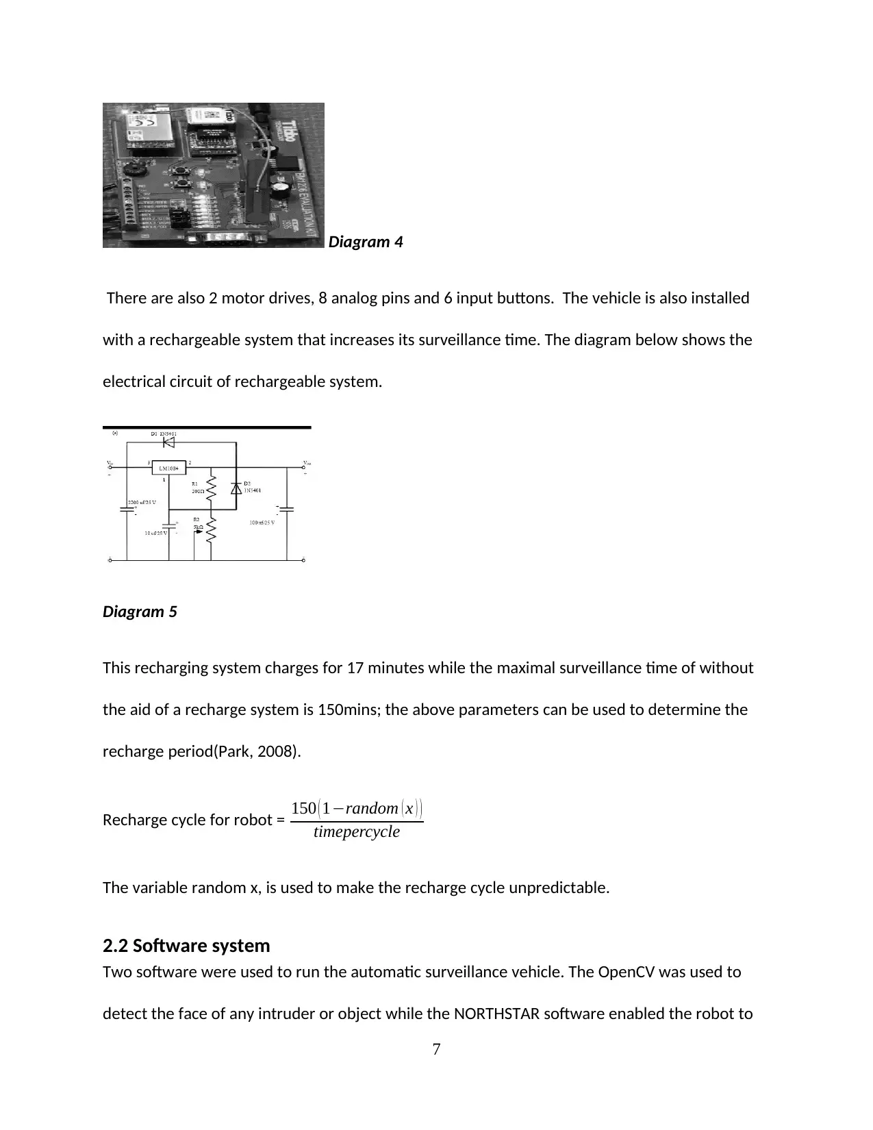
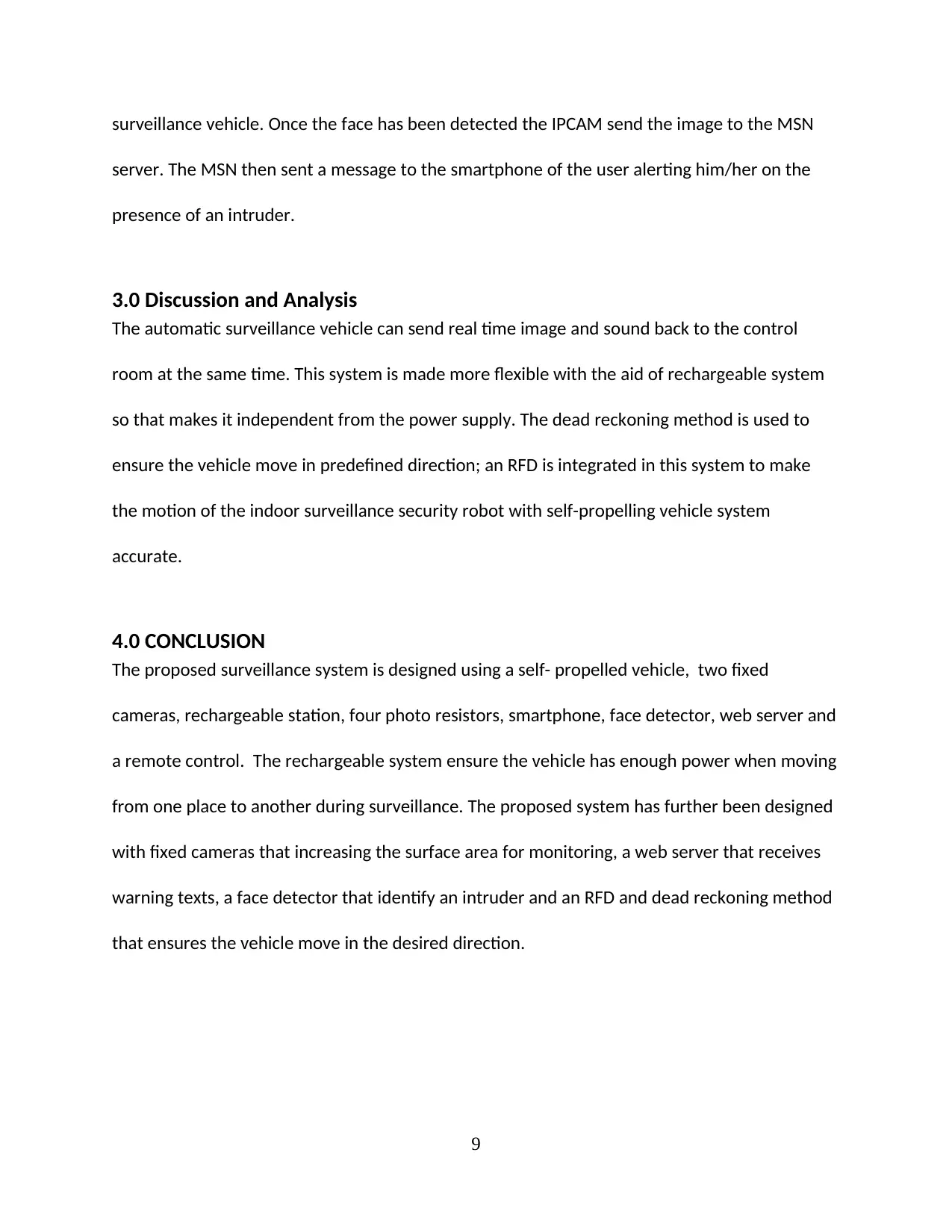
Diagram 4
There are also 2 motor drives, 8 analog pins and 6 input buttons. The vehicle is also installed
with a rechargeable system that increases its surveillance time. The diagram below shows the
electrical circuit of rechargeable system.
Diagram 5
This recharging system charges for 17 minutes while the maximal surveillance time of without
the aid of a recharge system is 150mins; the above parameters can be used to determine the
recharge period(Park, 2008).
Recharge cycle for robot = 150 ( 1−random ( x ) )
timepercycle
The variable random x, is used to make the recharge cycle unpredictable.
2.2 Software system
Two software were used to run the automatic surveillance vehicle. The OpenCV was used to
detect the face of any intruder or object while the NORTHSTAR software enabled the robot to
7
Paraphrase This Document
Need a fresh take? Get an instant paraphrase of this document with our AI Paraphraser

detect a MSN agent (Wang, 2007). The NORTHSTAR software was written using the C program
while the OpenCV was written using the modern JAVA language.
2.3 Experimental results
The working principle of the automatic indoor security surveillance vehicle was demonstrated
with the help of simple experiment. The notebook computer is used to play the role played by
web servers. Two cameras are fixed on the right and left of the floor together with 4 photo
resistors that are placed on the floor.
The face detector reacted by sending a warning message when the face of an intruder was
detected as shown in the figure below
This was simulated by allowing a person to enter the restricted area while avoiding the
surveillance camera. The intruder was still captured by the automatic indoor security
8
surveillance vehicle. Once the face has been detected the IPCAM send the image to the MSN
server. The MSN then sent a message to the smartphone of the user alerting him/her on the
presence of an intruder.
3.0 Discussion and Analysis
The automatic surveillance vehicle can send real time image and sound back to the control
room at the same time. This system is made more flexible with the aid of rechargeable system
so that makes it independent from the power supply. The dead reckoning method is used to
ensure the vehicle move in predefined direction; an RFD is integrated in this system to make
the motion of the indoor surveillance security robot with self-propelling vehicle system
accurate.
4.0 CONCLUSION
The proposed surveillance system is designed using a self- propelled vehicle, two fixed
cameras, rechargeable station, four photo resistors, smartphone, face detector, web server and
a remote control. The rechargeable system ensure the vehicle has enough power when moving
from one place to another during surveillance. The proposed system has further been designed
with fixed cameras that increasing the surface area for monitoring, a web server that receives
warning texts, a face detector that identify an intruder and an RFD and dead reckoning method
that ensures the vehicle move in the desired direction.
9
⊘ This is a preview!⊘
Do you want full access?
Subscribe today to unlock all pages.

Trusted by 1+ million students worldwide
5.0 REFERENCE
Cheng, C. (2007). Remote surveillance by network robot using WLAN and mobile IPv6
techniques. Proceedings of the IEEE Region 10 Conference TENCON, October 30-November 2,
2007, Taipei, pp: 1-4.
Huh, K (2010) Intelligent surveillance and security robot systems. Proceedings of the IEEE
Workshop on Advanced Robotics and its Social Impacts, pp. 26-28,.
Lee, H. (2011). Indoor surveillance security robot with a self-propelled patrolling vehicle. J.
Robot.
Lin, Y. (2010). A visual surveillance system for mobile robot using omnidirectional and PTZ
cameras. Proceedings of the SICE Annual Conference, August 18-21, 2010, Taipei, pp: 37-42.
Park, J. (2008).A design of mobile robot based on Network Camera and sound source
localization for intelligent surveillance system. Proceedings of the International Conference on
Control, Automation and Systems, , pp: 674-678.
Tsai, A. (2007). NCCU security warrior: An intelligent security robot system. Proceedings of the
33rd Annual Conference of the IEEE Industrial Electronics Society, November 5-8, 2007,pp: 2960-
2965.
Wang, Y. (2007). Utilization of deformable templates in real-time face tracking system. Master
Thesis, National Sun Yat-Sen University, Taiwan.
Zhang, Y. (2009). Surveillance and tracking system with collaboration of robots, sensor nodes
and RFID tags. Proceedings of 18th International Conference on Computer Communications and
Networks, pp: 1-6.
10
Paraphrase This Document
Need a fresh take? Get an instant paraphrase of this document with our AI Paraphraser

11
1 out of 11
Your All-in-One AI-Powered Toolkit for Academic Success.
+13062052269
info@desklib.com
Available 24*7 on WhatsApp / Email
![[object Object]](/_next/static/media/star-bottom.7253800d.svg)
Unlock your academic potential
Copyright © 2020–2026 A2Z Services. All Rights Reserved. Developed and managed by ZUCOL.
