Information System: Repair-Made Easy
VerifiedAdded on 2022/11/09
|22
|2221
|242
AI Summary
This report discusses the design and system evaluation of Repair-Made Easy using DFD level 0 diagram, context diagram, and Entity relationship diagram. It also includes the identification of critical use cases, data elements requirement, CRUD diagram, and prototype of website design and architecture. Subject: Information System, Course Code: NA, Course Name: NA, College/University: NA
Contribute Materials
Your contribution can guide someone’s learning journey. Share your
documents today.

Running head: INFORMATION SYSTEM: REPAIR-MADE EASY
Information System: Repair-Made Easy
Name of the Student
Name of the University
Author Note
Information System: Repair-Made Easy
Name of the Student
Name of the University
Author Note
Secure Best Marks with AI Grader
Need help grading? Try our AI Grader for instant feedback on your assignments.
1INFORMATION SYSTEM: REPAIR-MADE EASY
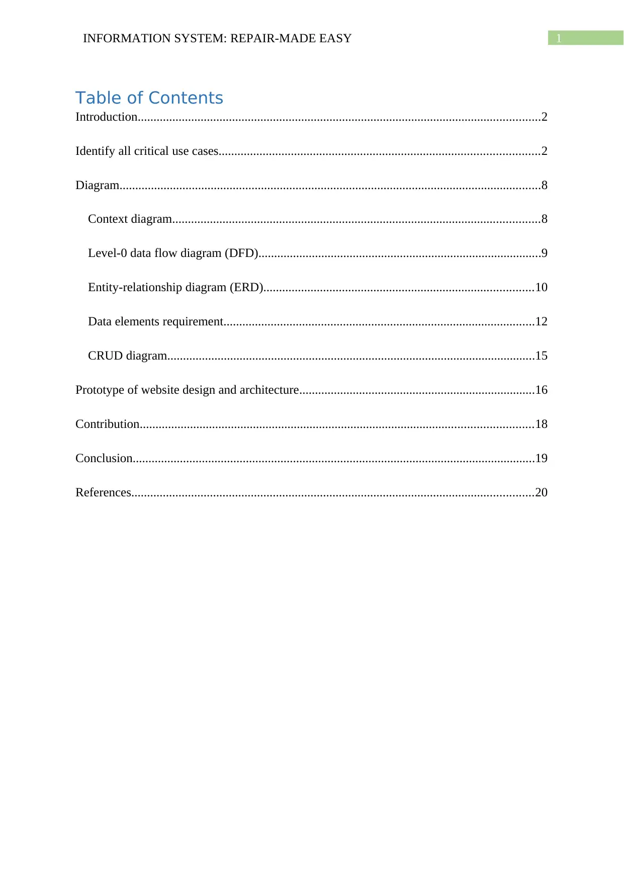
Table of Contents
Introduction................................................................................................................................2
Identify all critical use cases......................................................................................................2
Diagram......................................................................................................................................8
Context diagram.....................................................................................................................8
Level-0 data flow diagram (DFD)..........................................................................................9
Entity-relationship diagram (ERD)......................................................................................10
Data elements requirement...................................................................................................12
CRUD diagram.....................................................................................................................15
Prototype of website design and architecture...........................................................................16
Contribution.............................................................................................................................18
Conclusion................................................................................................................................19
References................................................................................................................................20
2INFORMATION SYSTEM: REPAIR-MADE EASY
Introduction
System development is mainly the process of design, analyse, implement and
maintenance. The system analysis and design is done for the identification of the system
requirements according to its usability (Dennis, Wixom and Roth 2018). Also, the purpose
and the goal of the system is defined in this phase. The goal of the system can achieved by
breaking up it into the smaller objectives as the processes. These objectives are achieved step
by step to later run the system to fulfil the entire requirement (Romiszowski 2016). The
owner of the Repair-Made-Easy, John is thinking of the transforming its revenue and
expenditure based Service Company to a live system where the services can be provided and
the structured. The company also wants to maintain all the information using an information
system implementation (Laudon and Laudon 2016). This report indents to discuss and
explain the design and system evaluation that has been done by modelling using DFD level 0
diagram, context diagram, and Entity relationship diagram.
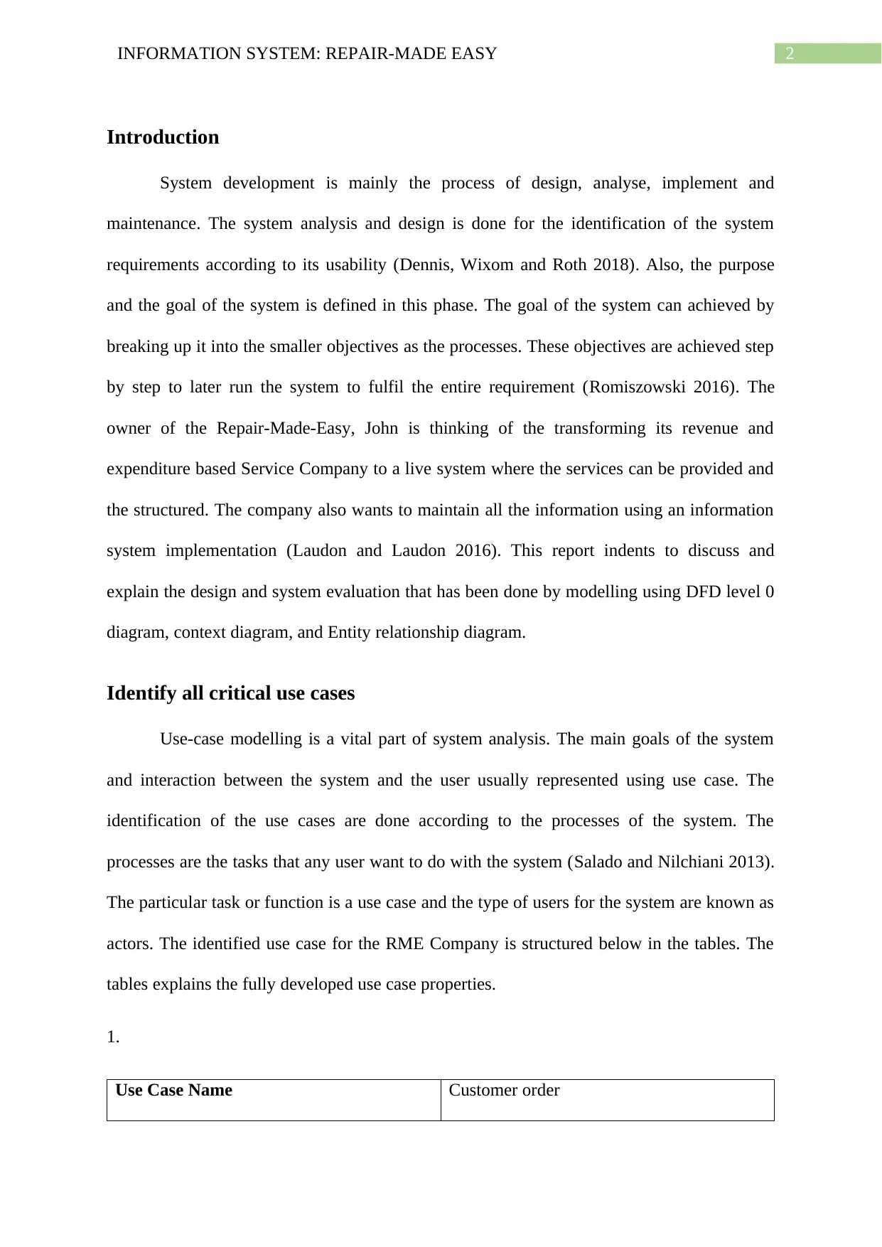
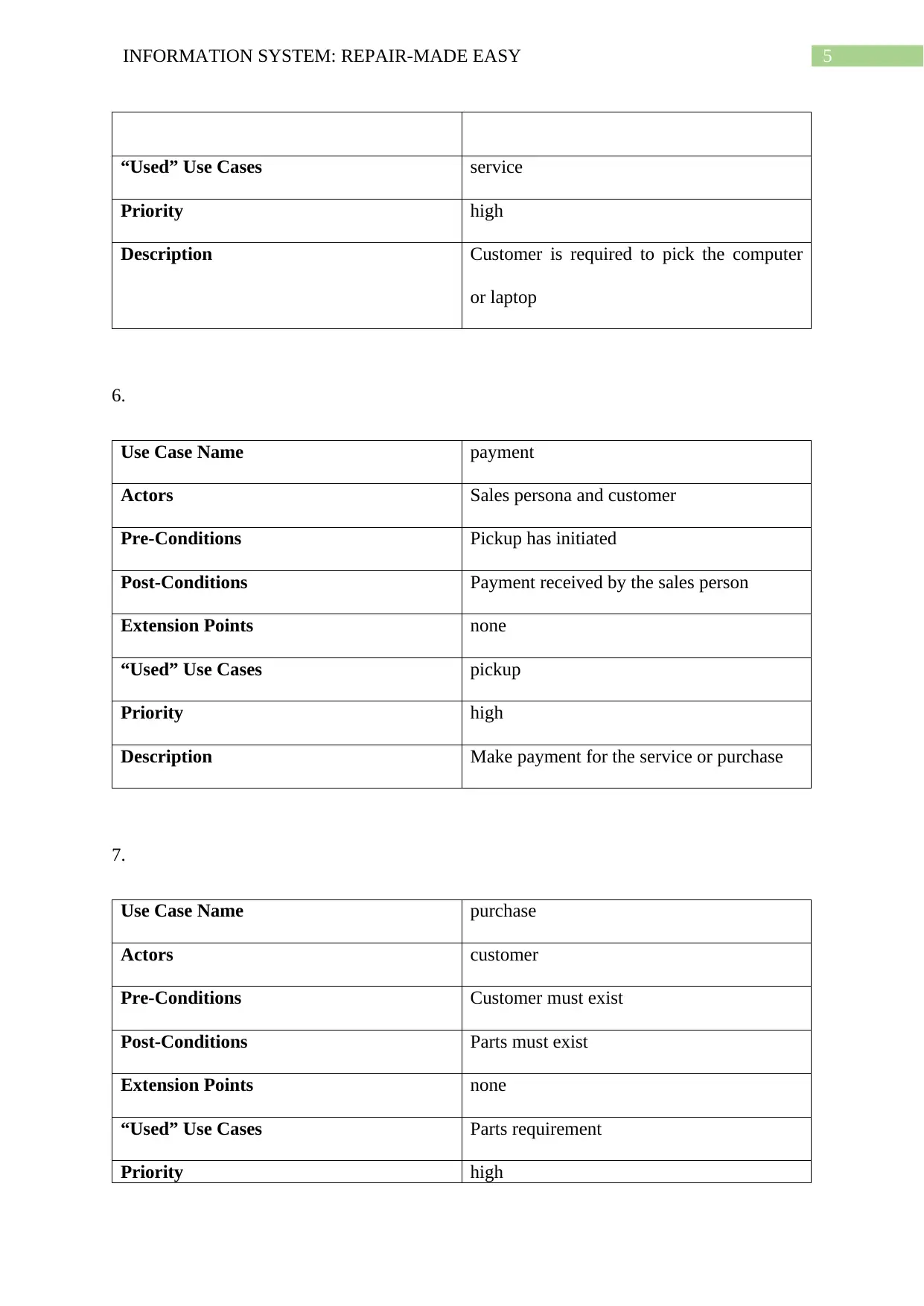
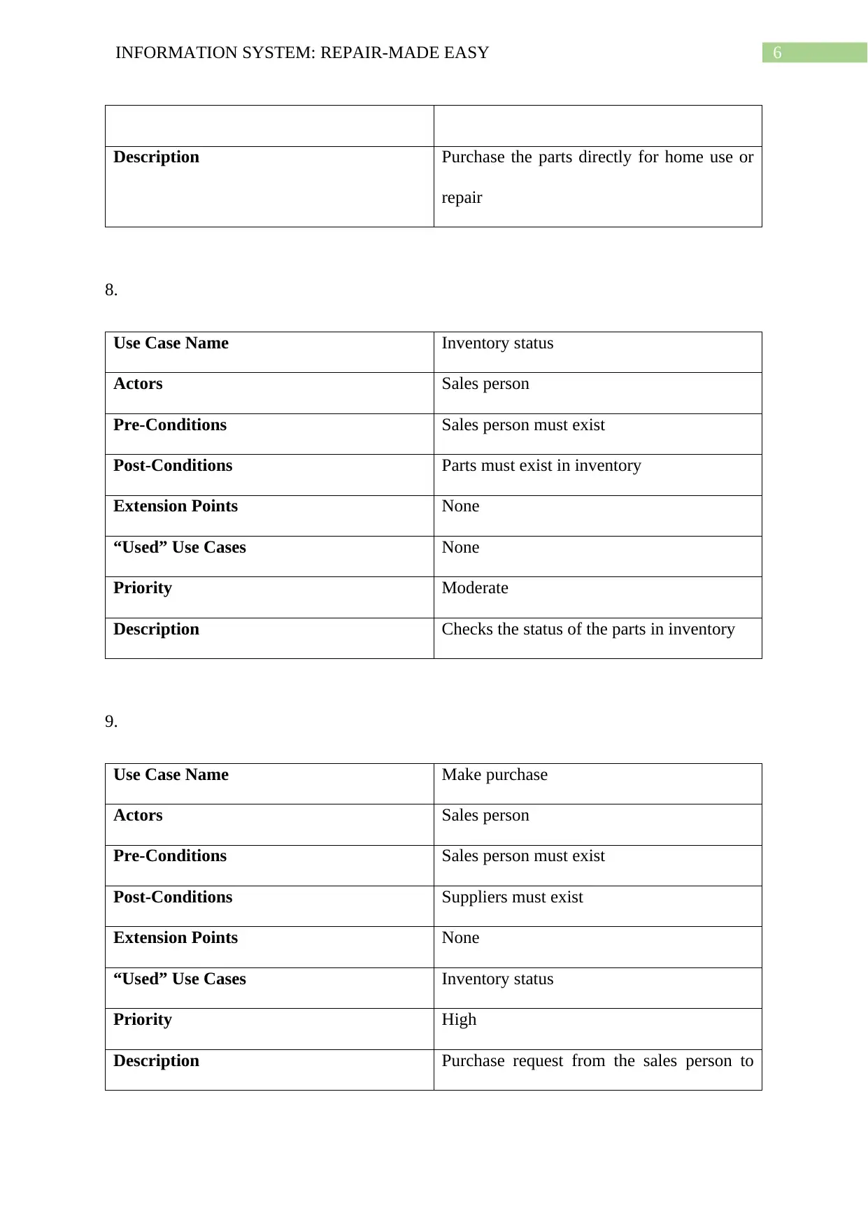
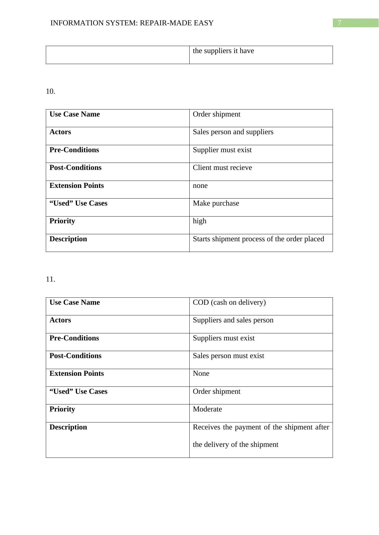
Identify all critical use cases
Use-case modelling is a vital part of system analysis. The main goals of the system
and interaction between the system and the user usually represented using use case. The
identification of the use cases are done according to the processes of the system. The
processes are the tasks that any user want to do with the system (Salado and Nilchiani 2013).
The particular task or function is a use case and the type of users for the system are known as
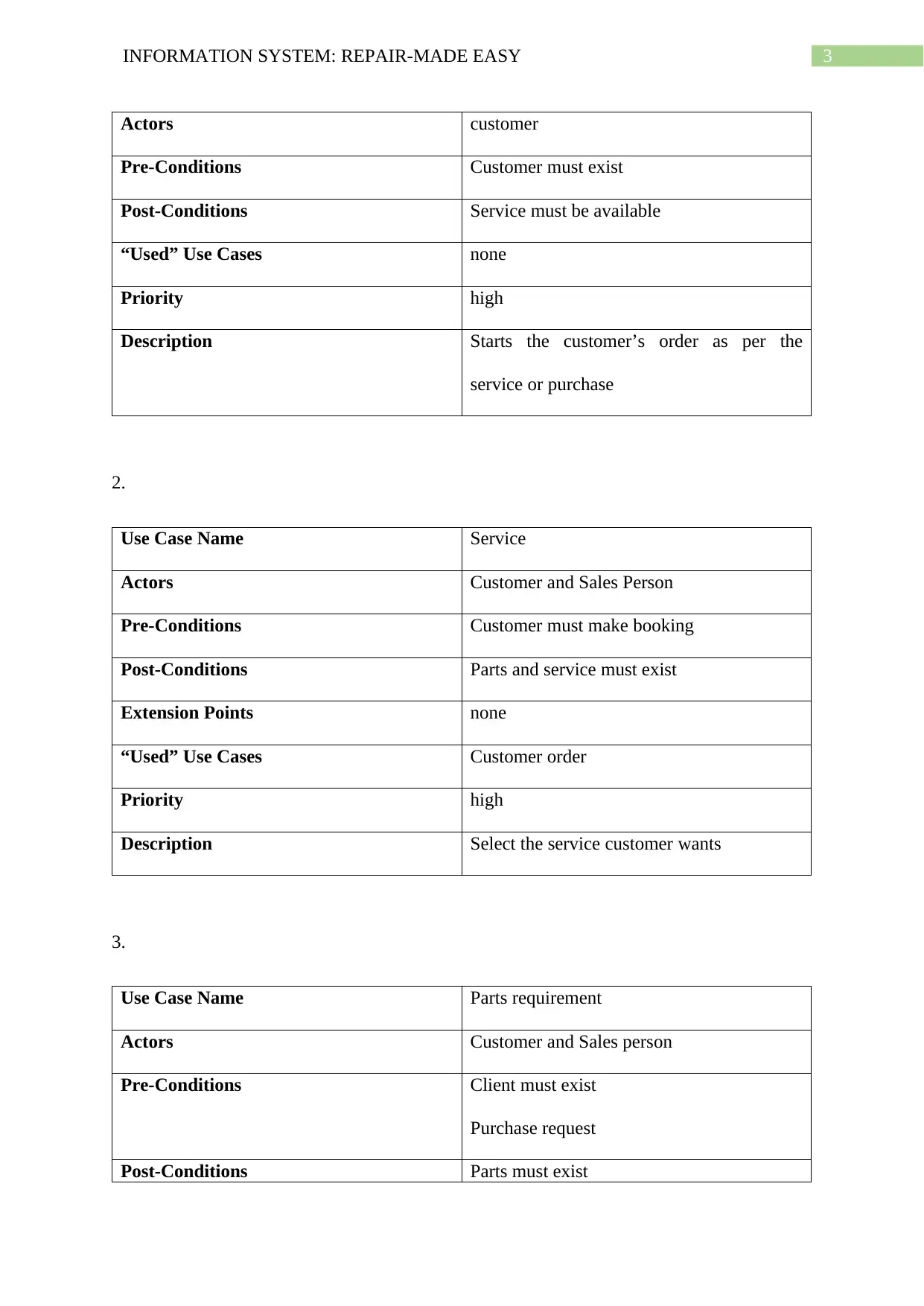
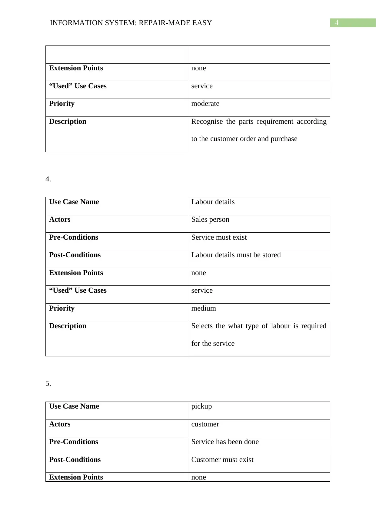
actors. The identified use case for the RME Company is structured below in the tables. The
tables explains the fully developed use case properties.
1.
Use Case Name Customer order
3INFORMATION SYSTEM: REPAIR-MADE EASY
Actors customer
Pre-Conditions Customer must exist
Post-Conditions Service must be available
“Used” Use Cases none
Priority high
Description Starts the customer’s order as per the
service or purchase
2.
Use Case Name Service
Actors Customer and Sales Person
Pre-Conditions Customer must make booking
Post-Conditions Parts and service must exist
Extension Points none
“Used” Use Cases Customer order
Priority high
Description Select the service customer wants
3.
Use Case Name Parts requirement
Actors Customer and Sales person
Pre-Conditions Client must exist
Purchase request
Post-Conditions Parts must exist
Secure Best Marks with AI Grader
Need help grading? Try our AI Grader for instant feedback on your assignments.
4INFORMATION SYSTEM: REPAIR-MADE EASY
Extension Points none
“Used” Use Cases service
Priority moderate
Description Recognise the parts requirement according
to the customer order and purchase
4.
Use Case Name Labour details
Actors Sales person
Pre-Conditions Service must exist
Post-Conditions Labour details must be stored
Extension Points none
“Used” Use Cases service
Priority medium
Description Selects the what type of labour is required
for the service
5.
Use Case Name pickup
Actors customer
Pre-Conditions Service has been done
Post-Conditions Customer must exist
Extension Points none
Extension Points none
“Used” Use Cases service
Priority moderate
Description Recognise the parts requirement according
to the customer order and purchase
4.
Use Case Name Labour details
Actors Sales person
Pre-Conditions Service must exist
Post-Conditions Labour details must be stored
Extension Points none
“Used” Use Cases service
Priority medium
Description Selects the what type of labour is required
for the service
5.
Use Case Name pickup
Actors customer
Pre-Conditions Service has been done
Post-Conditions Customer must exist
Extension Points none
5INFORMATION SYSTEM: REPAIR-MADE EASY
“Used” Use Cases service
Priority high
Description Customer is required to pick the computer
or laptop
6.
Use Case Name payment
Actors Sales persona and customer
Pre-Conditions Pickup has initiated
Post-Conditions Payment received by the sales person
Extension Points none
“Used” Use Cases pickup
Priority high
Description Make payment for the service or purchase
7.
Use Case Name purchase
Actors customer
Pre-Conditions Customer must exist
Post-Conditions Parts must exist
Extension Points none
“Used” Use Cases Parts requirement
Priority high
6INFORMATION SYSTEM: REPAIR-MADE EASY
Description Purchase the parts directly for home use or
repair
8.
Use Case Name Inventory status
Actors Sales person
Pre-Conditions Sales person must exist
Post-Conditions Parts must exist in inventory
Extension Points None
“Used” Use Cases None
Priority Moderate
Description Checks the status of the parts in inventory
9.
Use Case Name Make purchase
Actors Sales person
Pre-Conditions Sales person must exist
Post-Conditions Suppliers must exist
Extension Points None
“Used” Use Cases Inventory status
Priority High
Description Purchase request from the sales person to
Paraphrase This Document
Need a fresh take? Get an instant paraphrase of this document with our AI Paraphraser
7INFORMATION SYSTEM: REPAIR-MADE EASY
the suppliers it have
10.
Use Case Name Order shipment
Actors Sales person and suppliers
Pre-Conditions Supplier must exist
Post-Conditions Client must recieve
Extension Points none
“Used” Use Cases Make purchase
Priority high
Description Starts shipment process of the order placed
11.
Use Case Name COD (cash on delivery)
Actors Suppliers and sales person
Pre-Conditions Suppliers must exist
Post-Conditions Sales person must exist
Extension Points None
“Used” Use Cases Order shipment
Priority Moderate
Description Receives the payment of the shipment after
the delivery of the shipment
8INFORMATION SYSTEM: REPAIR-MADE EASY
Diagram
The diagram helps in analysing the system in a structure analysis (Wang et al. 2016).
The diagrams used for the development for the revenue and expenditure cycles are the
context diagrams, level 0 DFD and an ER diagram.
Context diagram
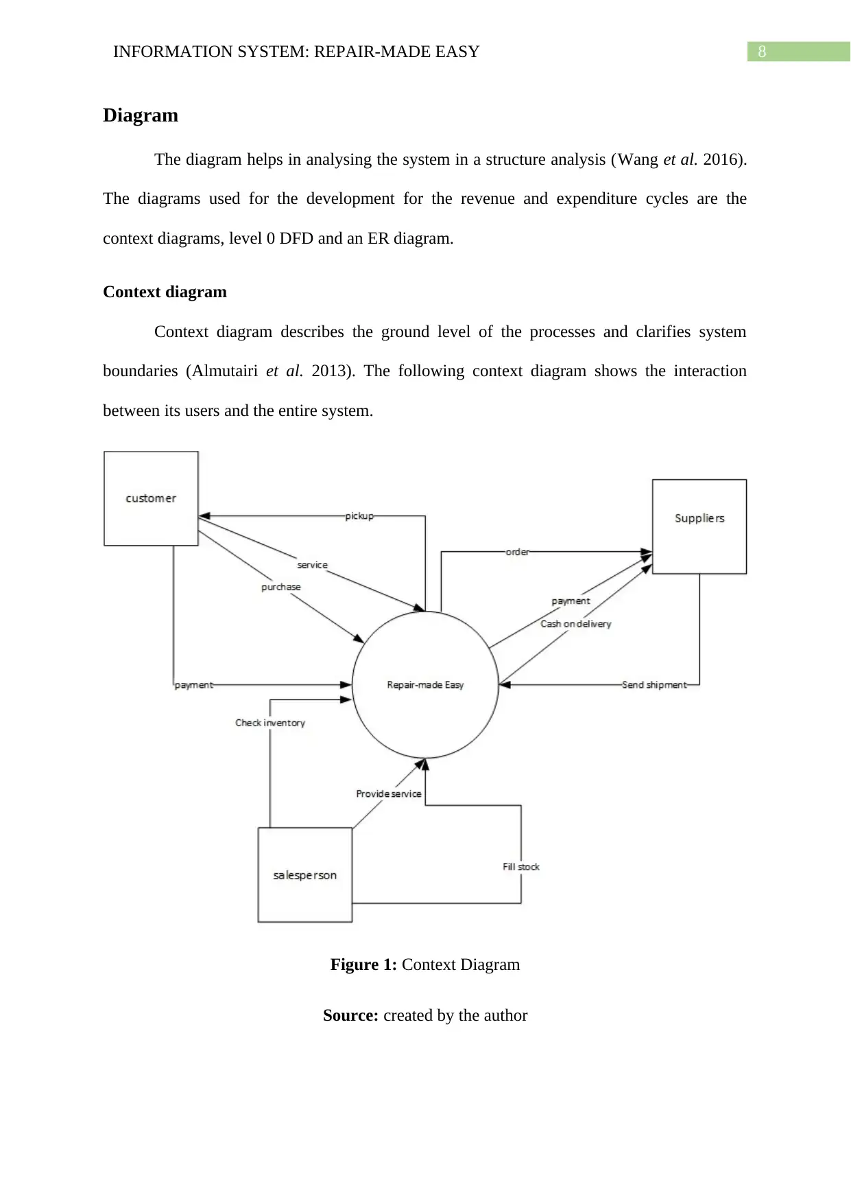
Context diagram describes the ground level of the processes and clarifies system
boundaries (Almutairi et al. 2013). The following context diagram shows the interaction
between its users and the entire system.
Figure 1: Context Diagram
Source: created by the author
9INFORMATION SYSTEM: REPAIR-MADE EASY
Level-0 data flow diagram (DFD)
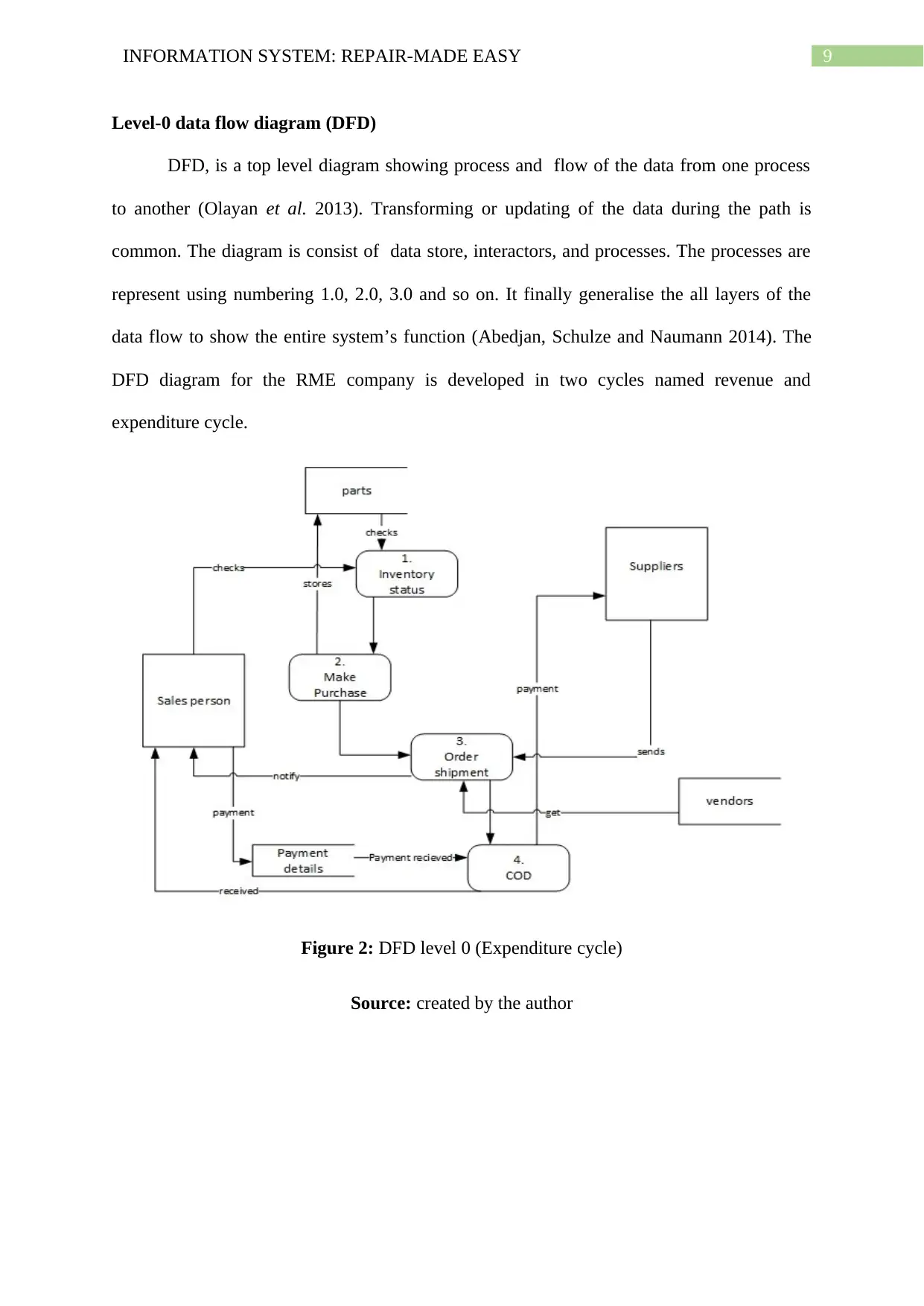
DFD, is a top level diagram showing process and flow of the data from one process
to another (Olayan et al. 2013). Transforming or updating of the data during the path is
common. The diagram is consist of data store, interactors, and processes. The processes are
represent using numbering 1.0, 2.0, 3.0 and so on. It finally generalise the all layers of the
data flow to show the entire system’s function (Abedjan, Schulze and Naumann 2014). The
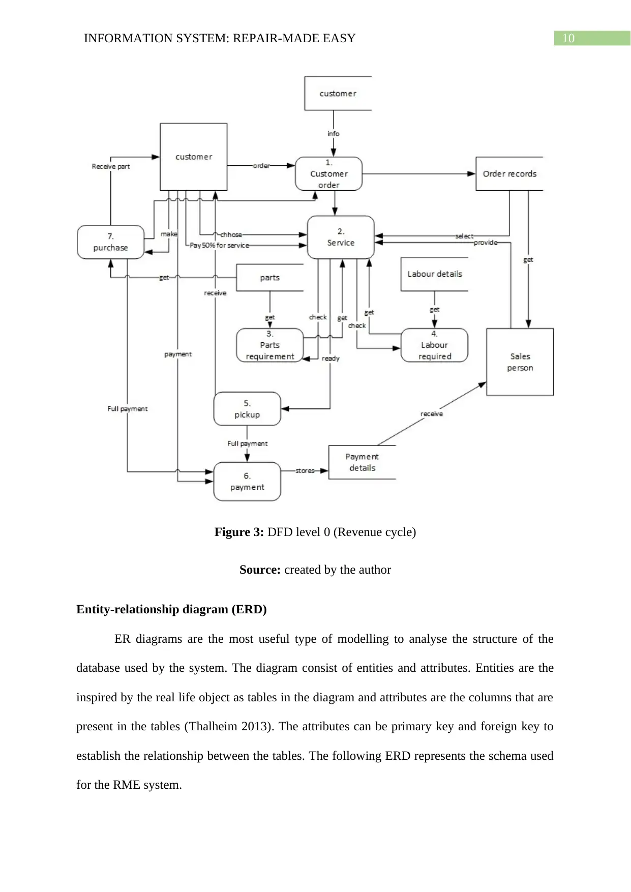
DFD diagram for the RME company is developed in two cycles named revenue and
expenditure cycle.
Figure 2: DFD level 0 (Expenditure cycle)
Source: created by the author
Secure Best Marks with AI Grader
Need help grading? Try our AI Grader for instant feedback on your assignments.
10INFORMATION SYSTEM: REPAIR-MADE EASY
Figure 3: DFD level 0 (Revenue cycle)
Source: created by the author
Entity-relationship diagram (ERD)
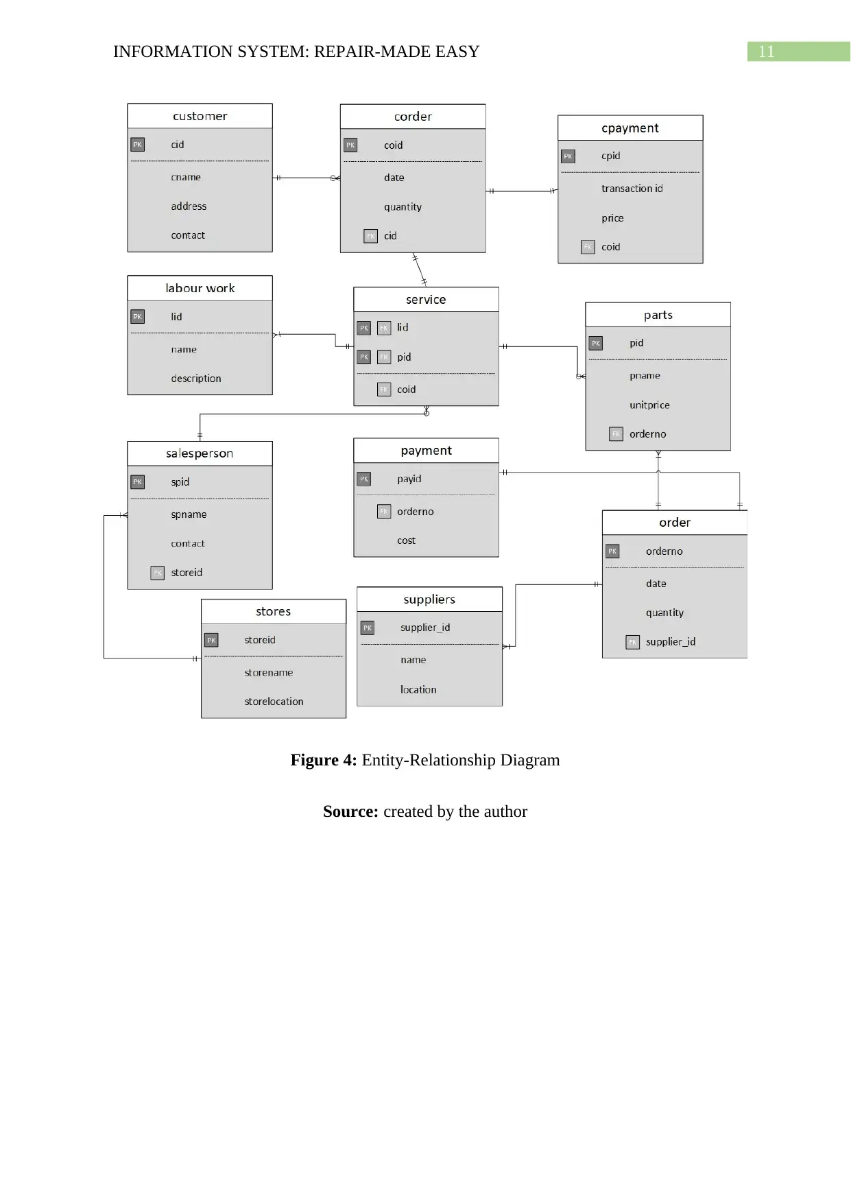
ER diagrams are the most useful type of modelling to analyse the structure of the
database used by the system. The diagram consist of entities and attributes. Entities are the
inspired by the real life object as tables in the diagram and attributes are the columns that are
present in the tables (Thalheim 2013). The attributes can be primary key and foreign key to
establish the relationship between the tables. The following ERD represents the schema used
for the RME system.
11INFORMATION SYSTEM: REPAIR-MADE EASY
Figure 4: Entity-Relationship Diagram
Source: created by the author
Figure 4: Entity-Relationship Diagram
Source: created by the author
12INFORMATION SYSTEM: REPAIR-MADE EASY
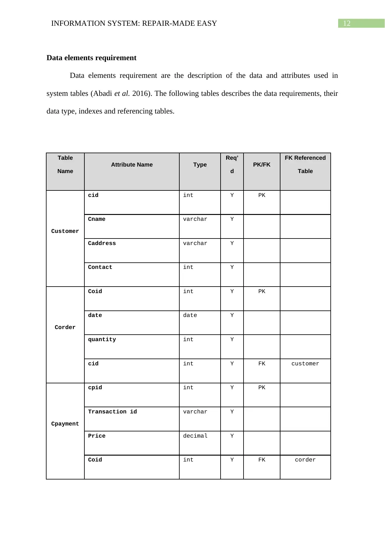
Data elements requirement
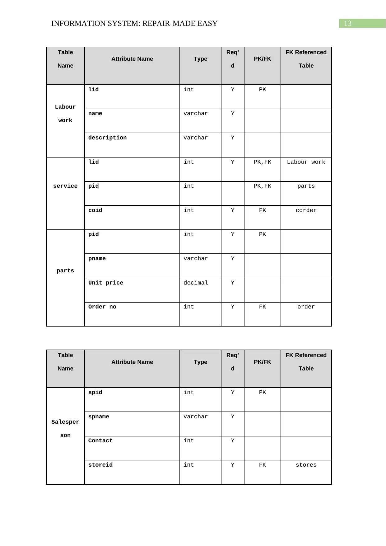
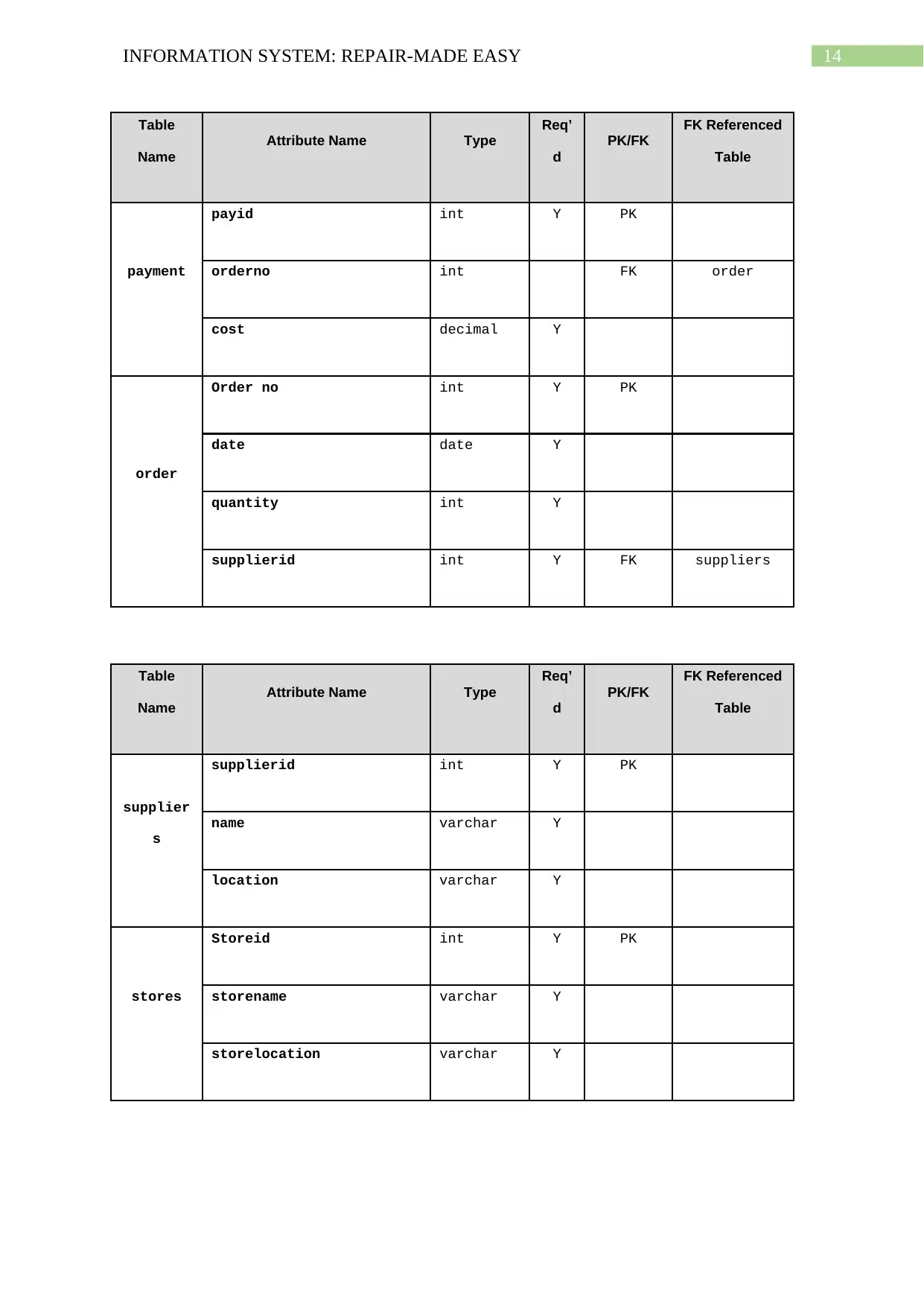
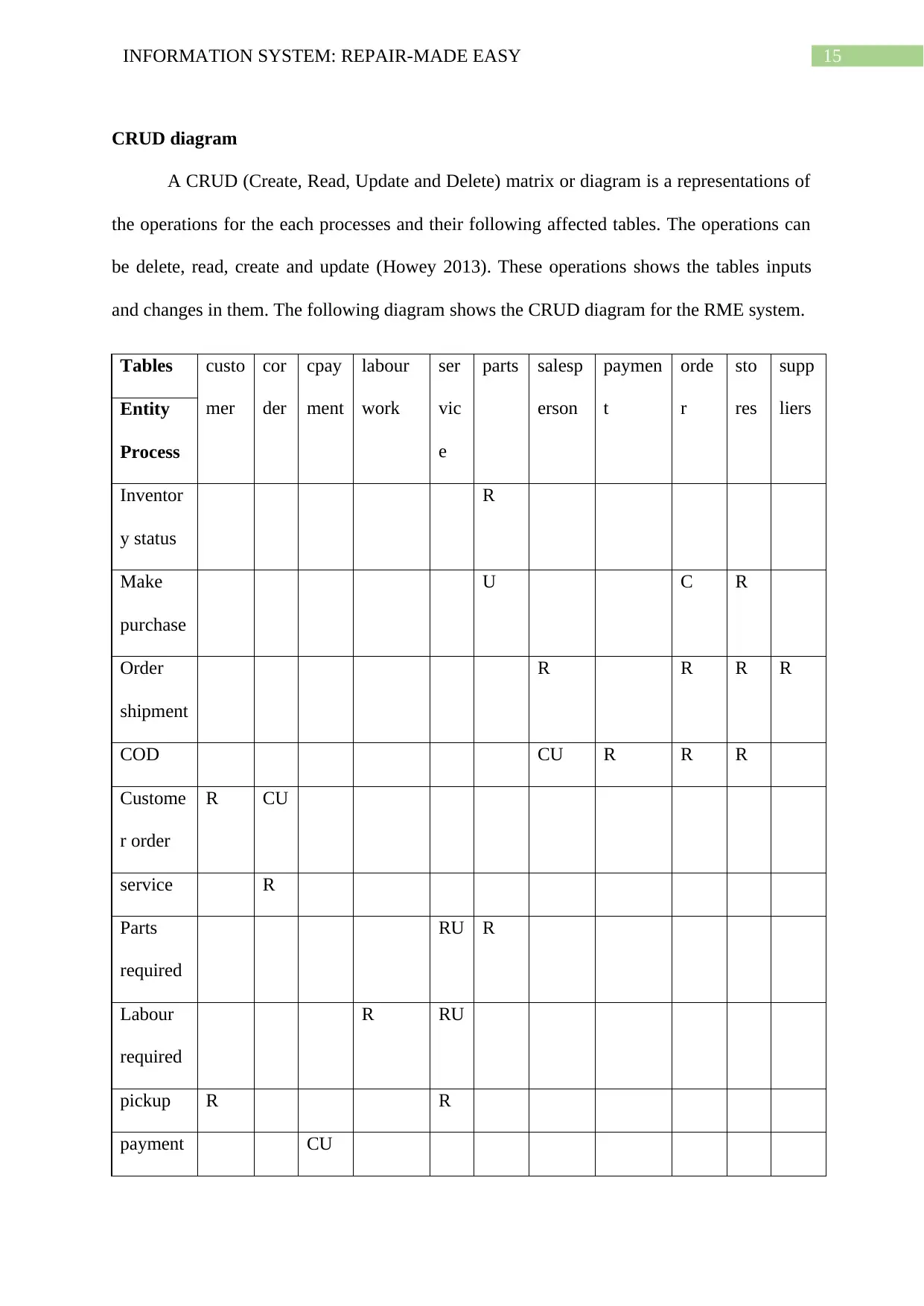
Data elements requirement are the description of the data and attributes used in
system tables (Abadi et al. 2016). The following tables describes the data requirements, their
data type, indexes and referencing tables.
Table
Name
Attribute Name Type
Req’
d
PK/FK
FK Referenced
Table
Customer
cid int Y PK
Cname varchar Y
Caddress varchar Y
Contact int Y
Corder
Coid int Y PK
date date Y
quantity int Y
cid int Y FK customer
Cpayment
cpid int Y PK
Transaction id varchar Y
Price decimal Y
Coid int Y FK corder
Paraphrase This Document
Need a fresh take? Get an instant paraphrase of this document with our AI Paraphraser
13INFORMATION SYSTEM: REPAIR-MADE EASY
Table
Name
Attribute Name Type
Req’
d
PK/FK
FK Referenced
Table
Labour
work
lid int Y PK
name varchar Y
description varchar Y
service
lid int Y PK,FK Labour work
pid int PK,FK parts
coid int Y FK corder
parts
pid int Y PK
pname varchar Y
Unit price decimal Y
Order no int Y FK order
Table
Name
Attribute Name Type
Req’
d
PK/FK
FK Referenced
Table
Salesper
son
spid int Y PK
spname varchar Y
Contact int Y
storeid int Y FK stores
Table
Name
Attribute Name Type
Req’
d
PK/FK
FK Referenced
Table
Labour
work
lid int Y PK
name varchar Y
description varchar Y
service
lid int Y PK,FK Labour work
pid int PK,FK parts
coid int Y FK corder
parts
pid int Y PK
pname varchar Y
Unit price decimal Y
Order no int Y FK order
Table
Name
Attribute Name Type
Req’
d
PK/FK
FK Referenced
Table
Salesper
son
spid int Y PK
spname varchar Y
Contact int Y
storeid int Y FK stores
14INFORMATION SYSTEM: REPAIR-MADE EASY
Table
Name
Attribute Name Type
Req’
d
PK/FK
FK Referenced
Table
payment
payid int Y PK
orderno int FK order
cost decimal Y
order
Order no int Y PK
date date Y
quantity int Y
supplierid int Y FK suppliers
Table
Name
Attribute Name Type
Req’
d
PK/FK
FK Referenced
Table
supplier
s
supplierid int Y PK
name varchar Y
location varchar Y
stores
Storeid int Y PK
storename varchar Y
storelocation varchar Y
Table
Name
Attribute Name Type
Req’
d
PK/FK
FK Referenced
Table
payment
payid int Y PK
orderno int FK order
cost decimal Y
order
Order no int Y PK
date date Y
quantity int Y
supplierid int Y FK suppliers
Table
Name
Attribute Name Type
Req’
d
PK/FK
FK Referenced
Table
supplier
s
supplierid int Y PK
name varchar Y
location varchar Y
stores
Storeid int Y PK
storename varchar Y
storelocation varchar Y
15INFORMATION SYSTEM: REPAIR-MADE EASY
CRUD diagram
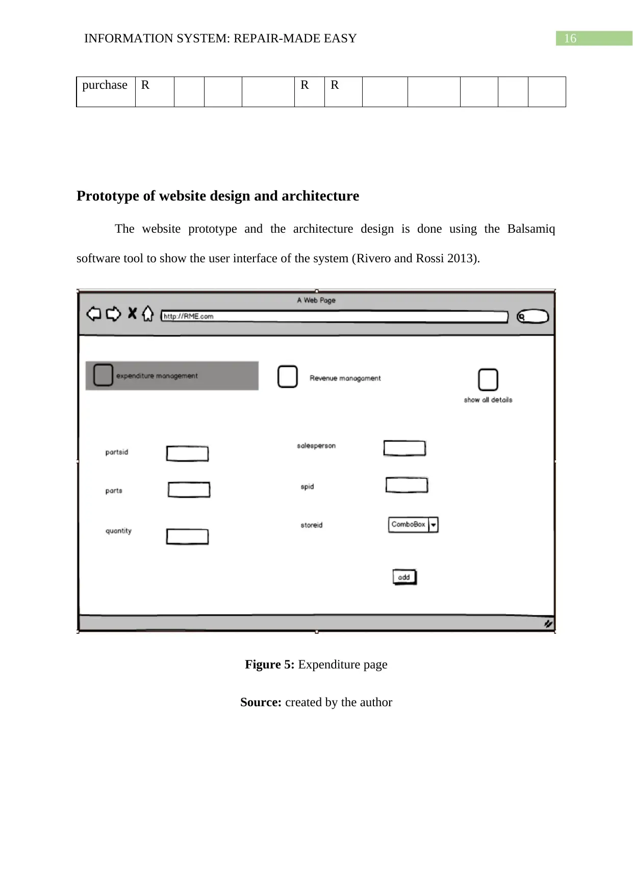
A CRUD (Create, Read, Update and Delete) matrix or diagram is a representations of
the operations for the each processes and their following affected tables. The operations can
be delete, read, create and update (Howey 2013). These operations shows the tables inputs
and changes in them. The following diagram shows the CRUD diagram for the RME system.
Tables custo
mer
cor
der
cpay
ment
labour
work
ser
vic
e
parts salesp
erson
paymen
t
orde
r
sto
res
supp
liersEntity
Process
Inventor
y status
R
Make
purchase
U C R
Order
shipment
R R R R
COD CU R R R
Custome
r order
R CU
service R
Parts
required
RU R
Labour
required
R RU
pickup R R
payment CU
Secure Best Marks with AI Grader
Need help grading? Try our AI Grader for instant feedback on your assignments.
16INFORMATION SYSTEM: REPAIR-MADE EASY
purchase R R R
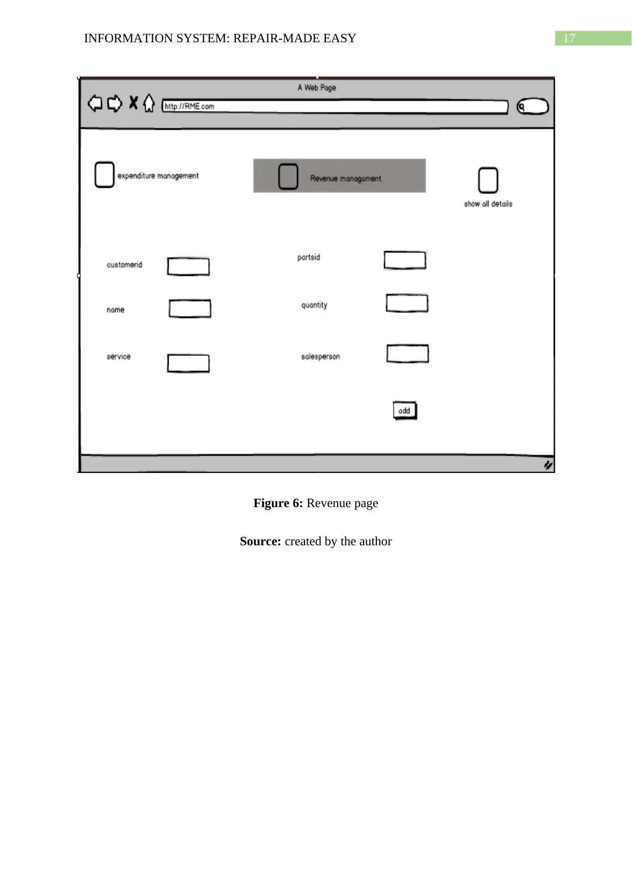
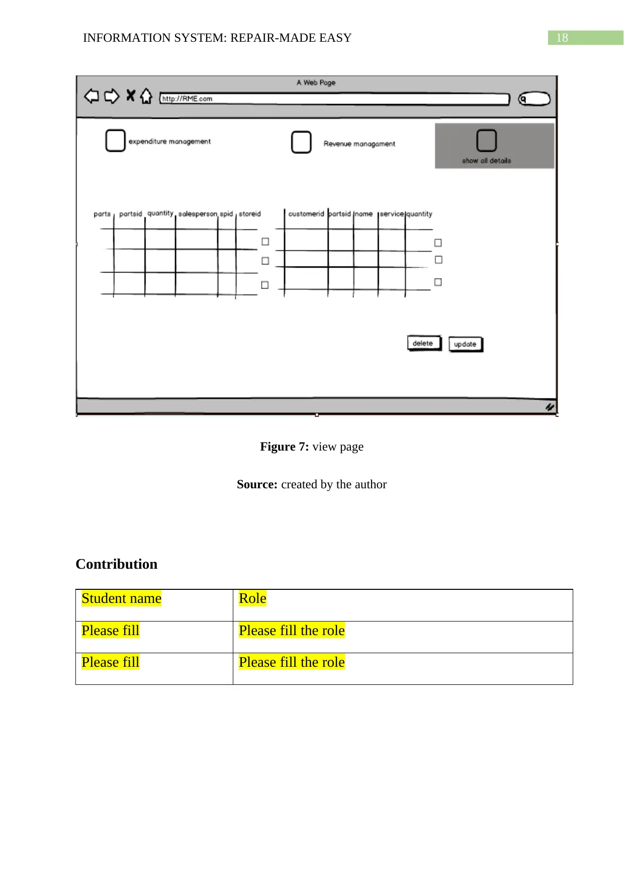
Prototype of website design and architecture
The website prototype and the architecture design is done using the Balsamiq
software tool to show the user interface of the system (Rivero and Rossi 2013).
Figure 5: Expenditure page
Source: created by the author
purchase R R R
Prototype of website design and architecture
The website prototype and the architecture design is done using the Balsamiq
software tool to show the user interface of the system (Rivero and Rossi 2013).
Figure 5: Expenditure page
Source: created by the author
17INFORMATION SYSTEM: REPAIR-MADE EASY
Figure 6: Revenue page
Source: created by the author
Figure 6: Revenue page
Source: created by the author
18INFORMATION SYSTEM: REPAIR-MADE EASY
Figure 7: view page
Source: created by the author
Contribution
Student name Role
Please fill Please fill the role
Please fill Please fill the role
Figure 7: view page
Source: created by the author
Contribution
Student name Role
Please fill Please fill the role
Please fill Please fill the role
Paraphrase This Document
Need a fresh take? Get an instant paraphrase of this document with our AI Paraphraser
19INFORMATION SYSTEM: REPAIR-MADE EASY
Conclusion
The design and analysing of the system is the first phase in the system development.
Hence it is very required to identify the usability requirements of the proposed system. The
provided case study has provided lots of support for the development of the diagrams and
tables. The identification of the use cases is done with the help of the business process of
RME. Later, on the basis of the use case the DFD level 0 is developed and context diagram
too. The entity relationship diagram is also developed successfully as per the used data stores
in the DFD diagram. At last, the crud matrix and the prototype of the webpage is developed
using software tools. Hence it can be said that all the objectives of the system design and
analysis have been successfully done.
20INFORMATION SYSTEM: REPAIR-MADE EASY
References
Abadi, D., Bajda-Pawlikowski, K., Abouzied, A. and Silberschatz, A., Yale University,
2016. Processing of data using a database system in communication with a data processing
framework. U.S. Patent 9,495,427.
Abedjan, Z., Schulze, P. and Naumann, F., 2014, November. DFD: Efficient functional
dependency discovery. In Proceedings of the 23rd ACM International Conference on
Conference on Information and Knowledge Management (pp. 949-958). ACM.
Almutairi, S., Abu-Samaha, A., Bell, G. and Chen, F., 2013, October. An enhanced use case
diagram to model Context Aware Systems. In 2013 Science and Information Conference (pp.
270-274). IEEE.
Dennis, A., Wixom, B.H. and Roth, R.M., 2018. Systems analysis and design. John wiley &
sons.
Howey, R., OptumInsight Inc, 2013. Apparatus, system, and method for identifying
redundancy and consolidation opportunities in databases and application systems. U.S. Patent
8,364,651.
Laudon, K.C. and Laudon, J.P., 2016. Management information system. Pearson Education
India.
Olayan, N., Patu, V., Matsuno, Y. and Yamamoto, S., 2013, November. A dependability
assurance method based on Data Flow Diagram (DFD). In 2013 European Modelling
Symposium (pp. 113-118). IEEE.
Rivero, J.M. and Rossi, G., 2013, July. MockupDD: Facilitating agile support for model-
driven web engineering. In International Conference on Web Engineering (pp. 325-329).
Springer, Cham.
21INFORMATION SYSTEM: REPAIR-MADE EASY
Romiszowski, A.J., 2016. Designing instructional systems: Decision making in course
planning and curriculum design. Routledge.
Salado, A. and Nilchiani, R., 2013. Contextual-and behavioral-centric stakeholder
identification. Procedia Computer Science, 16, pp.908-917.
Thalheim, B., 2013. Entity-relationship modeling: foundations of database technology.
Springer Science & Business Media.
Wang, J.W., Wang, H.F., Ding, J.L., Furuta, K., Kanno, T., Ip, W.H. and Zhang, W.J., 2016.
On domain modelling of the service system with its application to enterprise information
systems. Enterprise Information Systems, 10(1), pp.1-16.
1 out of 22
Related Documents
Your All-in-One AI-Powered Toolkit for Academic Success.
+13062052269
info@desklib.com
Available 24*7 on WhatsApp / Email
![[object Object]](/_next/static/media/star-bottom.7253800d.svg)
Unlock your academic potential
© 2024 | Zucol Services PVT LTD | All rights reserved.


