Failure Modes and Mechanisms in Cast Iron Water Pipe
VerifiedAdded on 2023/03/31
|8
|1427
|209
AI Summary
This article discusses the various failure modes and mechanisms in cast iron water pipes, including blowout holes, circumferential cracking, bell shearing, spiral cracking, longitudinal cracking, and bell splitting. It also explores the type of corrosion in cast iron pipes and the effects of expansive soils and climate change on buried pipes. Additionally, it provides information on the empirical failure criteria for large diameter pipes and the estimation of maximum pipe stress and factor of safety based on stress. The article concludes with a calculation of the required pipe stiffness factor for controlling deflection in different trench widths.
Contribute Materials
Your contribution can guide someone’s learning journey. Share your
documents today.
INFRASTRUCTURE DETERORIATION MODELING
By Name
Course
Instructor
Institution
Location
Date
By Name
Course
Instructor
Institution
Location
Date
Secure Best Marks with AI Grader
Need help grading? Try our AI Grader for instant feedback on your assignments.
Question 1: Failure modes and mechanism in cast iron water pipe
Blowout holes: Corrosion pitting takes place till the pipe wall has been thinned to the extent the
pressure of the water pushes out the left quite thin pipe wall. This kind of corrosion failure may
generate a relatively small hole or even a large one as influenced by how the process of localized
corrosion has been as well the pressure that the pipe experiences (Mahmoodian and Li, 2018).
Circumferential cracking is a common mode of failure in pipes having small diameters. The
resultant failure takes place in a way that is same as twig snapping in which crack of failure
propagates across pipe circumferences. The failure mode may be as well as result of movements
of soil generating tensile forces on pipe resulting in non-complex tensile failure.
Bell shearing: Pipes with large diameter often have very relatively high inertia moment to
generate circumferential failures. Nevertheless, gray cast iron pipes having large diameter often
fail through having part of bell shearing off (Pietrucha-Urbanik, 2015). Compressive forces acing
upon the pipe spigot towards the bell of the adjacent pipe within pipeline may be a possible
cause for this mode of failure. The bending forces are nevertheless possibly resulting in this
failure type. Any simple compressive loading may tend to generate crack which travels down
entire pipe length
Spiral Cracking: This is commonly expected in pipes of medium diameters and involves a crack
that within the pipe seeming to begin in a circumferential manner thereafter propagating down
the whole pipe length in a manner that is spiral. The look of this mode of failure suggests the
failure is generated by combination of internal pressure as well as bending forces.
Longitudinal cracking: This mode of failure tends to be limited to pipes of large diameters. The
failure may be as a result of the pressure of the internal water, crushing forces on pipes or likely
compressive forces that act along pipe (Pietrucha-Urbanik, 2015). As soon as the crack is
initiated it may move along the length of pipe. In some instances, cracks have been witnessed on
the opposite sides of pipe leading to part of pipe generating a hole which is the same length as
the pipe.
Bell splitting: Tends to be very common in little diameter pipes. The joints found in cast iron
pipes were before covered with rope packed between spigot of one pipe and bell of the other.
This was then followed by pouring of molten lead to ensure completion of the seal. Leadite was
used as a replacement for lead and due to the fact that leadite has a different expansion
coefficient from lead, very low temperature at the pipe resulted in splitting of the bell.
Question 2: Type of corrosion in cast iron pipe
The primary corrosion form in cast iron pipe is localized corrosion. Characterization of the
treated of corrosion as well as feature of the cast iron pipes is normally influenced by such
features as graphite, ferrite as well as pearlite flakes. The degree to which some phases exists
within the microstructure for instance graphite and pearlite flakes (Pietrucha-Urbanik, 2015). In
general, the rate of corrosion for the various specimens from the ferritic pipes is often noticed to
be relatively lower than the one of pearlite pipes. The failure analysis of cast iron water pipes is
influenced by the morphology of the products of corrosion and the look of the failed surface has
effects on the examination of the post failure. This means knowledge of the surface would appear
like upon being exposed to the environment is needed for an understanding if the failure of the
pipes was catastrophic.
The active dissolution of iron as well as OH ions absorption on the ferrous surfaces have a great
influence on the cast iron pipes behaviors when in aerated water. It is anticipated that the rate of
dissolution would increase to result in more alkalinity of the solution (Pietrucha-Urbanik, 2015).
Still when under neutral conditions, the mechanism looks to be regulated by ion species diffusion
even as the process is seemingly under the control of the cathodic as well as anodic reactions
when subjected to alkaline chloride solutions. In determination of the rate of carrion which is a
factor of the solution and the specimen conditions, each method has a drawback that may lead to
obtaining misleading results by the method in case proper interpretation is not done. In some
instances, the values as determined from a single method do not explain the actual behavior of
corrosion.
Question 3: Effects of expansive soils and climate change on buried pipes
The soil imposes certain movements when a pipe is buried inside it and as the soil moves there
is a change in the volume which may result in extra stresses on the pipe. Reactivity of the soil or
even shrink or swell behavior is determined by the variations of moisture in the soil. As the
variation in the soil moisture is linked with changes in the climate influencing seasonal changes,
droughts as well as rainfall, the pipe failure variation rates will changes as the moisture and thus
reactivity of soil being the only fact which may be variant with the seasonal changes in the
climate.
Question 4
The two main failure types that are experienced in cast iron water pipes are longitudinal as well
as circumferential fractures in which circumferential failures are often noted in large diameter
pipes while longitudinal failure is common in small diameter pipes. This is due to the fact that
small diameter pipes mainly respond to external loadings as well as differences in temperature
via longitudinal stresses which result in circumferential breaks even as large pipes have their
diameters largely fracturing longitudinally as a result of hoop stress (Jiang et al., 2019).
Secure Best Marks with AI Grader
Need help grading? Try our AI Grader for instant feedback on your assignments.
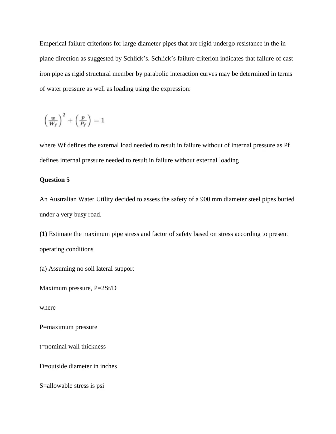
Emperical failure criterions for large diameter pipes that are rigid undergo resistance in the in-
plane direction as suggested by Schlick’s. Schlick’s failure criterion indicates that failure of cast
iron pipe as rigid structural member by parabolic interaction curves may be determined in terms
of water pressure as well as loading using the expression:
where Wf defines the external load needed to result in failure without of internal pressure as Pf
defines internal pressure needed to result in failure without external loading
Question 5
An Australian Water Utility decided to assess the safety of a 900 mm diameter steel pipes buried
under a very busy road.
(1) Estimate the maximum pipe stress and factor of safety based on stress according to present
operating conditions
(a) Assuming no soil lateral support
Maximum pressure, P=2St/D
where
P=maximum pressure
t=nominal wall thickness
D=outside diameter in inches
S=allowable stress is psi
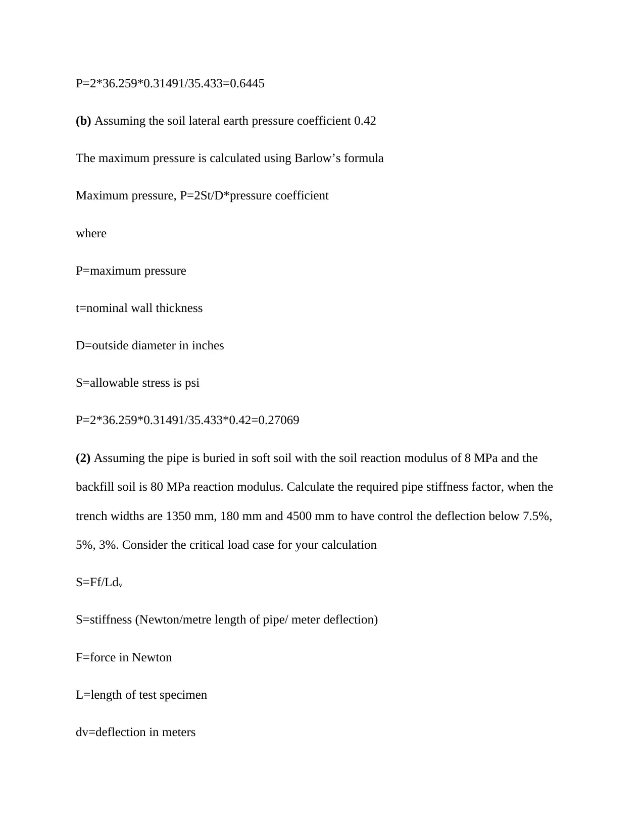
P=2*36.259*0.31491/35.433=0.6445
(b) Assuming the soil lateral earth pressure coefficient 0.42
The maximum pressure is calculated using Barlow’s formula
Maximum pressure, P=2St/D*pressure coefficient
where
P=maximum pressure
t=nominal wall thickness
D=outside diameter in inches
S=allowable stress is psi
P=2*36.259*0.31491/35.433*0.42=0.27069
(2) Assuming the pipe is buried in soft soil with the soil reaction modulus of 8 MPa and the
backfill soil is 80 MPa reaction modulus. Calculate the required pipe stiffness factor, when the
trench widths are 1350 mm, 180 mm and 4500 mm to have control the deflection below 7.5%,
5%, 3%. Consider the critical load case for your calculation
S=Ff/Ldv
S=stiffness (Newton/metre length of pipe/ meter deflection)
F=force in Newton
L=length of test specimen
dv=deflection in meters
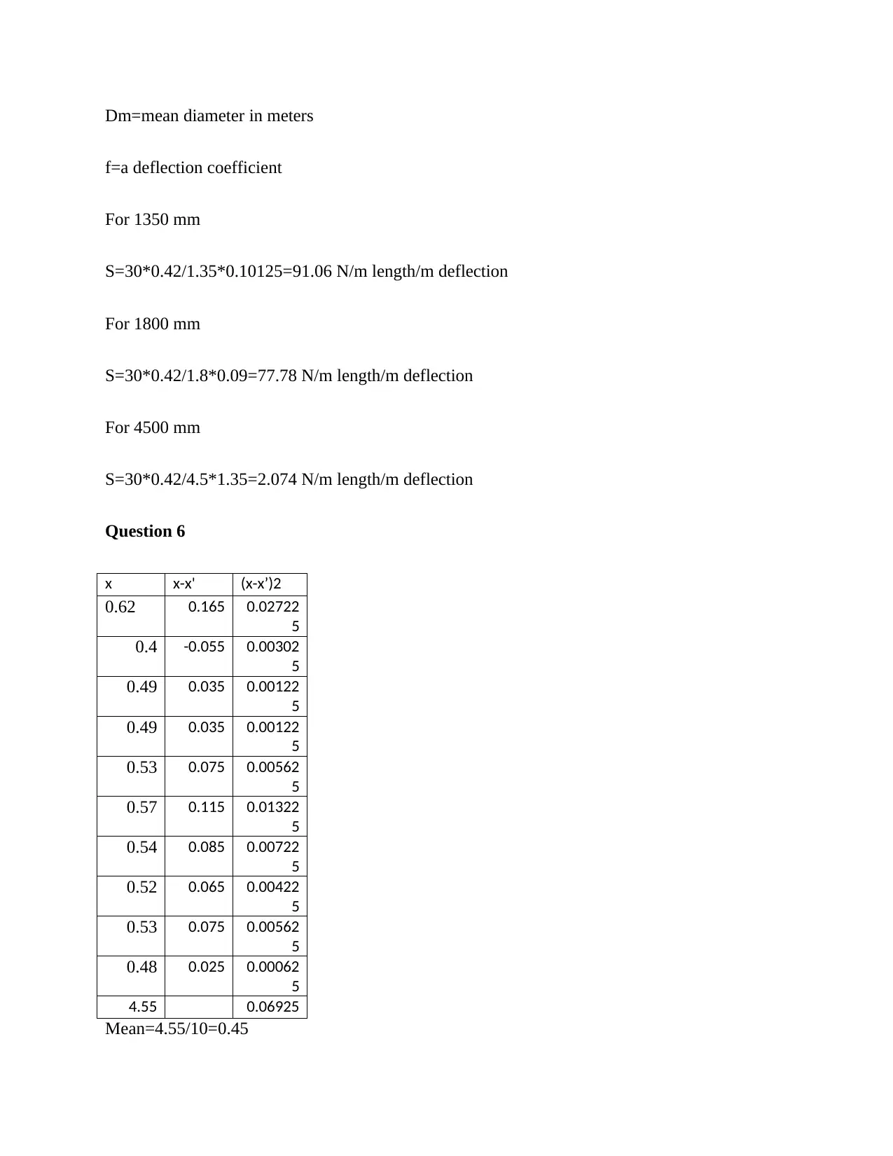
Dm=mean diameter in meters
f=a deflection coefficient
For 1350 mm
S=30*0.42/1.35*0.10125=91.06 N/m length/m deflection
For 1800 mm
S=30*0.42/1.8*0.09=77.78 N/m length/m deflection
For 4500 mm
S=30*0.42/4.5*1.35=2.074 N/m length/m deflection
Question 6
x x-x' (x-x’)2
0.62 0.165 0.02722
5
0.4 -0.055 0.00302
5
0.49 0.035 0.00122
5
0.49 0.035 0.00122
5
0.53 0.075 0.00562
5
0.57 0.115 0.01322
5
0.54 0.085 0.00722
5
0.52 0.065 0.00422
5
0.53 0.075 0.00562
5
0.48 0.025 0.00062
5
4.55 0.06925
Mean=4.55/10=0.45
Paraphrase This Document
Need a fresh take? Get an instant paraphrase of this document with our AI Paraphraser
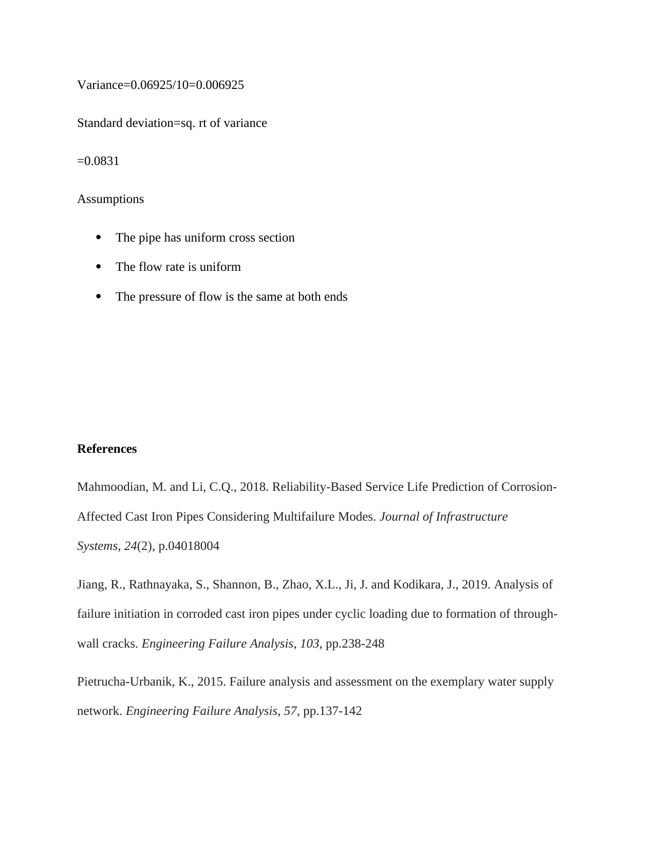
Variance=0.06925/10=0.006925
Standard deviation=sq. rt of variance
=0.0831
Assumptions
The pipe has uniform cross section
The flow rate is uniform
The pressure of flow is the same at both ends
References
Mahmoodian, M. and Li, C.Q., 2018. Reliability-Based Service Life Prediction of Corrosion-
Affected Cast Iron Pipes Considering Multifailure Modes. Journal of Infrastructure
Systems, 24(2), p.04018004
Jiang, R., Rathnayaka, S., Shannon, B., Zhao, X.L., Ji, J. and Kodikara, J., 2019. Analysis of
failure initiation in corroded cast iron pipes under cyclic loading due to formation of through-
wall cracks. Engineering Failure Analysis, 103, pp.238-248
Pietrucha-Urbanik, K., 2015. Failure analysis and assessment on the exemplary water supply
network. Engineering Failure Analysis, 57, pp.137-142
1 out of 8
Related Documents
Your All-in-One AI-Powered Toolkit for Academic Success.
+13062052269
info@desklib.com
Available 24*7 on WhatsApp / Email
![[object Object]](/_next/static/media/star-bottom.7253800d.svg)
Unlock your academic potential
© 2024 | Zucol Services PVT LTD | All rights reserved.
