Yardstick for innovation in Mobile Wireless Chargers
VerifiedAdded on 2023/06/08
|9
|1858
|392
AI Summary
The purpose of this report is to state the usage of a new type of wireless portable charger that is to be made available for the public so that the problem of the phones running out of charge is solved and the small devices may charge the phones without wires when needed. The study is conducted by testing products in various processes. The voltage of the charger is kept at 5V and testing is done under possible circumstances, and a handmade Digital Multimeter was put to usage to test the compatibility of the charger and the voltage of it.
Contribute Materials
Your contribution can guide someone’s learning journey. Share your
documents today.
Running head: COMMUNICATION FOR MEDIA
COMMUNICATION FOR MEDIA
Name of the Student
Name of the University
Author note:
COMMUNICATION FOR MEDIA
Name of the Student
Name of the University
Author note:
Secure Best Marks with AI Grader
Need help grading? Try our AI Grader for instant feedback on your assignments.
1COMMUNICATION FOR MEDIA
Memorandum
To:
From:
Date: 10.08.2018
Re: Yardstick for innovation in Mobile Wireless Chargers
______________________________________________________________________________
Study Overview
The purpose of this report is to state the usage of a new type of wireless portable charger
that is to be made available for the public so that the problem of the phones running out of
charge is solved and the small devices may charge the phones without wires when needed. The
study is conducted by testing products in various processes. The voltage of the charger is kept at
5V and testing is done under possible circumstances, and a handmade Digital Multimeter was
put to usage to test the compatibility of the charger and the voltage of it. The technology of
inducting charging is used but the various components have been kept comparatively smaller so
that the portability of the charger is maintained. The idea is to create a product that may be used
at various circumstances and the portability function is maintained.
Assessment Criteria
Cost
Portability
Size
Voltage fluctuation handling
Compatibility
2COMMUNICATION FOR MEDIA
Cost
The cost has to be set within 50 US Dollars so that people in general can afford the
individual products. The cost of each unit was considered in relationship to specialized operating, or
set up expenses. The chargers are minimalistic in design and minimum cost has been allocated for the
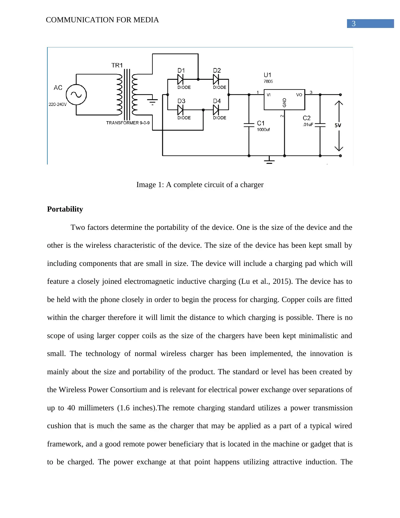
various components of the charger. The first component is the converter or step down transformer
that converts the high voltage into lower voltage in traditional charging devices, in this case this
device is modified so that it may store the current after converting it. The component used here is 9-
0-9 1A step-down transformer, which convert 220V AC to 9V AC (Circuitdigest.com, 2018). there
are primary and secondary coils in transformer which step up and increase or step down and decrease
the voltage according to the number of times of turn in the coils. This costs more or less 5 dollars.
The voltage required is 5v therefore the transformer must be of 7V. Other components are diodes for
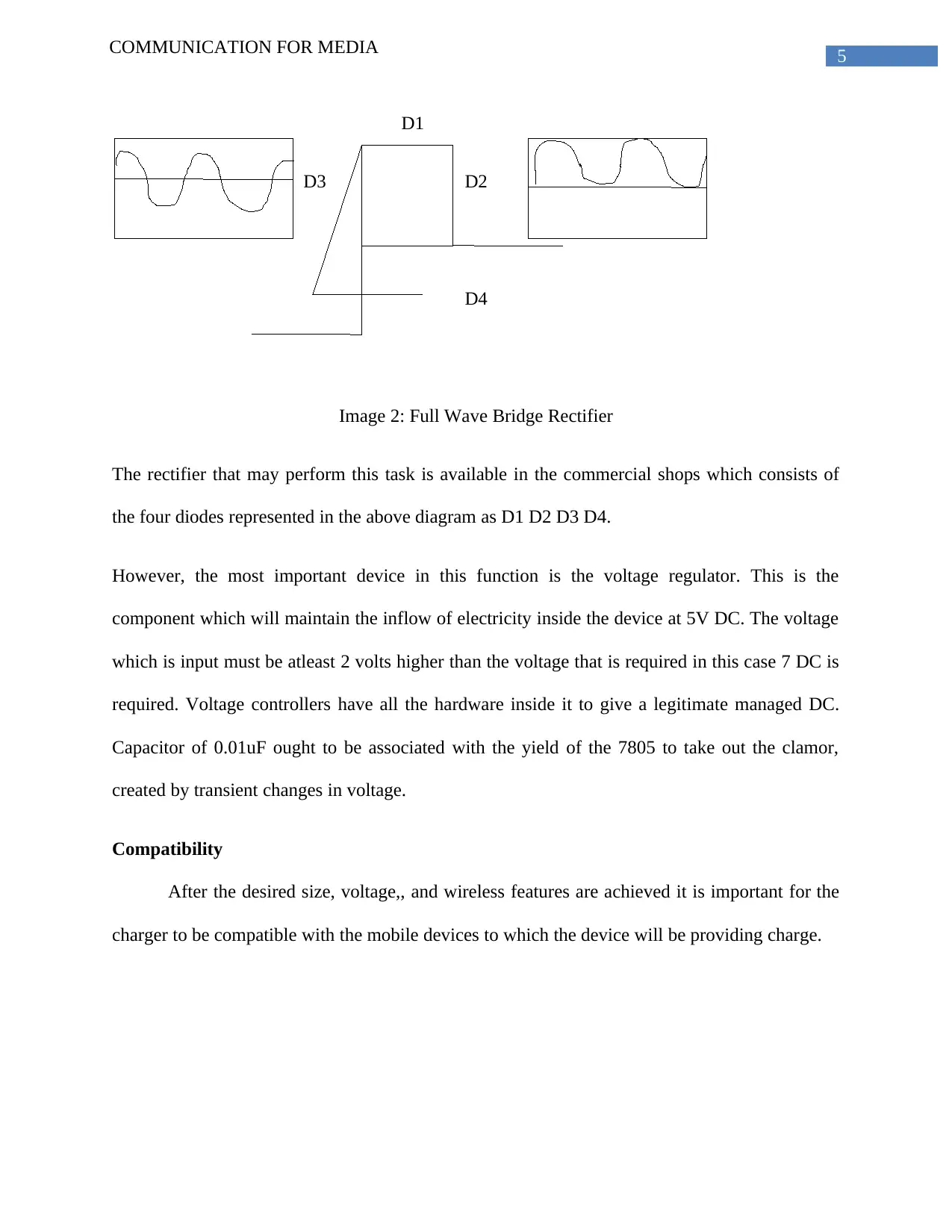
rectification of the Alternate Current or AC as it is known as. In first half cycle of AC diode D2 and
D3 are forward one-sided and D1 and D4 are turned around one-sided, and in the second half cycle
(negative half) Diode D1 and D4 are forward one-sided and D2 and D3 are switched one-sided. This
Combination changes over the negative half cycle into positive. Other components required are
Capacitor which charge till the waveform reaches its peak and discharge into Load circuit when
waveform goes truncated. The voltage needs to be regulated when the wireless charger is being
charged therefore there is requirement of a voltage regulator. The total cost of the equipments are
estimated at 30 US Dollars.
3COMMUNICATION FOR MEDIA
Image 1: A complete circuit of a charger
Portability
Two factors determine the portability of the device. One is the size of the device and the
other is the wireless characteristic of the device. The size of the device has been kept small by
including components that are small in size. The device will include a charging pad which will
feature a closely joined electromagnetic inductive charging (Lu et al., 2015). The device has to
be held with the phone closely in order to begin the process for charging. Copper coils are fitted
within the charger therefore it will limit the distance to which charging is possible. There is no
scope of using larger copper coils as the size of the chargers have been kept minimalistic and
small. The technology of normal wireless charger has been implemented, the innovation is
mainly about the size and portability of the product. The standard or level has been created by
the Wireless Power Consortium and is relevant for electrical power exchange over separations of
up to 40 millimeters (1.6 inches).The remote charging standard utilizes a power transmission
cushion that is much the same as the charger that may be applied as a part of a typical wired
framework, and a good remote power beneficiary that is located in the machine or gadget that is
to be charged. The power exchange at that point happens utilizing attractive induction. The
Secure Best Marks with AI Grader
Need help grading? Try our AI Grader for instant feedback on your assignments.
4COMMUNICATION FOR MEDIA
manner by which the remote power charging is accomplished adjusts to the standard and permits
a solitary remote charger from any provider to be utilized to charge any ideal gadget. As most
remote charging frameworks presently fit in with this standard, it implies that just a single
charger cushion is required to charge all gadgets.
Size
The size of the device is similar to the standard wired mobile charger, however it has
been designed to be wireless. Therefore the device is like the standard mobile charger without
the wire. The wireless charger presently are big in size and therefore the portability factor is low.
The objective is to maintain the wireless feature of the wireless charger and combine that with
the size of the wired chargers which are usually more portable. The device has the coils which
will be placed inside the charger having capability of charging devices from lesser distance (Kuo
et al., 2015). The mobile devices may be pressed against the chargers and held for some time and
the charging pad will charge the mobile device. The advantages of such charger will be the lesser
risk in electrical faults caused due to the wires and insulation failure and the durability of the
device as it will need lesser plugging in the electrical points. The device may be fitted with a
small indicator light to show the fullness of electrical charge within the device.
Voltage Fluctuation Handling
There are various smaller components within the wireless charger which work together in
handling the voltage fluctuation when the wireless charger is put into charging. The first step is
to convert the high strength A.C current into lower volts which can be handled by the device.
The transformer within the charger performs this particular action. The next step is the process
of rectification that includes deducting the negative fraction of the Alternate Current therefore
the fractional DC current is produced at that point. 4 diodes work together in this regards.
5COMMUNICATION FOR MEDIA
D1
D3 D2
D
D4
Image 2: Full Wave Bridge Rectifier
The rectifier that may perform this task is available in the commercial shops which consists of
the four diodes represented in the above diagram as D1 D2 D3 D4.
However, the most important device in this function is the voltage regulator. This is the
component which will maintain the inflow of electricity inside the device at 5V DC. The voltage
which is input must be atleast 2 volts higher than the voltage that is required in this case 7 DC is
required. Voltage controllers have all the hardware inside it to give a legitimate managed DC.
Capacitor of 0.01uF ought to be associated with the yield of the 7805 to take out the clamor,
created by transient changes in voltage.
Compatibility
After the desired size, voltage,, and wireless features are achieved it is important for the
charger to be compatible with the mobile devices to which the device will be providing charge.
6COMMUNICATION FOR MEDIA
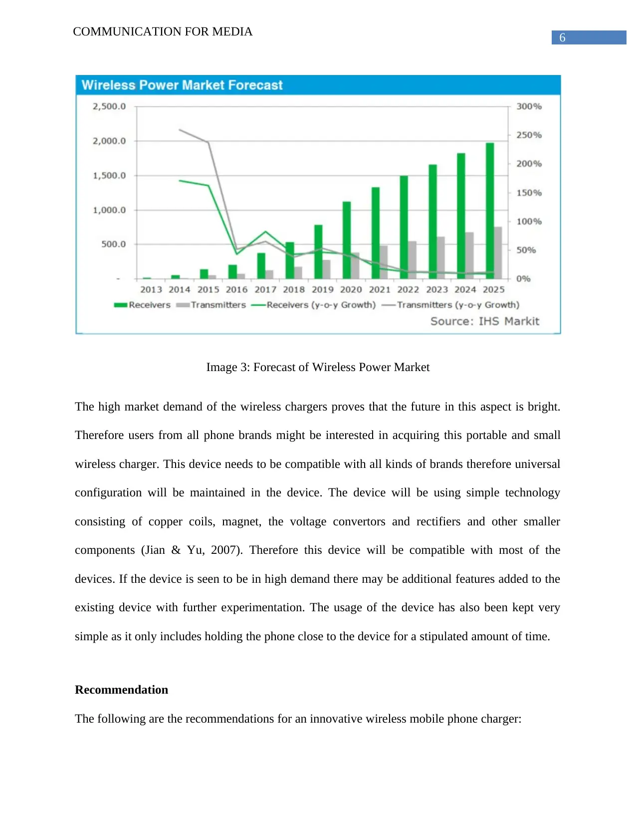
Image 3: Forecast of Wireless Power Market
The high market demand of the wireless chargers proves that the future in this aspect is bright.
Therefore users from all phone brands might be interested in acquiring this portable and small
wireless charger. This device needs to be compatible with all kinds of brands therefore universal
configuration will be maintained in the device. The device will be using simple technology
consisting of copper coils, magnet, the voltage convertors and rectifiers and other smaller
components (Jian & Yu, 2007). Therefore this device will be compatible with most of the
devices. If the device is seen to be in high demand there may be additional features added to the
existing device with further experimentation. The usage of the device has also been kept very
simple as it only includes holding the phone close to the device for a stipulated amount of time.
Recommendation
The following are the recommendations for an innovative wireless mobile phone charger:
Paraphrase This Document
Need a fresh take? Get an instant paraphrase of this document with our AI Paraphraser
7COMMUNICATION FOR MEDIA
1. The charger must be small and portable.
2. The charger must be charging the mobile devices very fast.
3. The charger should be having longevity.
4. The charger must be aesthetic to look at.
5. The charger must be compatible with maximum devices.
Conclusion
The demand for the wireless charging devices are increasing by the day. With increased
mobility and greater usage of smart phones it is imperative for people to carry their charger with
themselves. Therefore the wireless charger that would charge the phone by just keeping the
phone touched with the device. The device can be carried anywhere and the high capacity
charger is helpful in charging multiple mobile devices at a go. Still now charging from a very far
distance is unachieved, charging with the device touching or till a maximum of few feet.
8COMMUNICATION FOR MEDIA
Reference:
Circuitdigest.com (2018). Cell Phone Charger Circuit Diagram. [online] Circuitdigest.com.
Available at: https://circuitdigest.com/electronic-circuits/cell-phone-charger-circuit-
diagram [Accessed 5 Aug. 2018].
Jian, X. Z., & Yu, H. Z. (2007, October). A novel wireless charging system for movable
telephone with printed-circuit-board windings of different structure and shape
respectively. In Electrical Machines and Systems, 2007. ICEMS. International
Conference on (pp. 1283-1285). IEEE.
Kuo, R. C., Riehl, P., Satyamoorthy, A., Plumb, W., Tustin, P., & Lin, J. (2015, May). A 3D
resonant wireless charger for a wearable device and a mobile phone. In Wireless Power
Transfer Conference (WPTC), 2015 IEEE (pp. 1-3). IEEE.
Lu, X., Niyato, D., Wang, P., Kim, D. I., & Han, Z. (2015). Wireless charger networking for
mobile devices: Fundamentals, standards, and applications. IEEE Wireless
Communications, 22(2), 126-135.
1 out of 9
Your All-in-One AI-Powered Toolkit for Academic Success.
+13062052269
info@desklib.com
Available 24*7 on WhatsApp / Email
![[object Object]](/_next/static/media/star-bottom.7253800d.svg)
Unlock your academic potential
© 2024 | Zucol Services PVT LTD | All rights reserved.


