Ask a question from expert
Designing a Stub Feed Dipole Slot Antenna using CST Software
6 Pages2462 Words269 Views
Added on 2019-10-18
About This Document
This report discusses the design process of a stub feed dipole slot antenna using CST software. It covers the importance of feed impedance, Babinet's principle, and stub matching. The report also includes the results of simulations and optimization.
Designing a Stub Feed Dipole Slot Antenna using CST Software
Added on 2019-10-18
BookmarkShareRelated Documents
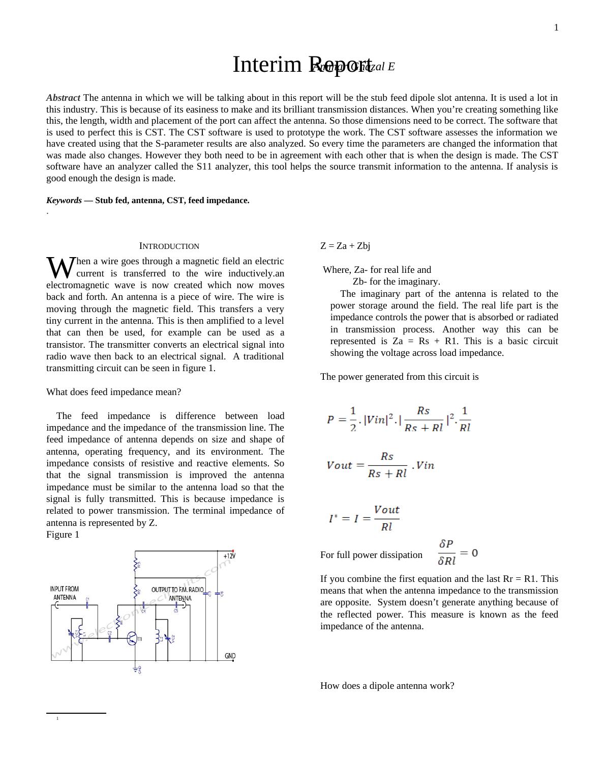
1Abstract The antenna in which we will be talking about in this report will be the stub feed dipole slot antenna. It is used a lot inthis industry. This is because of its easiness to make and its brilliant transmission distances. When you’re creating something likethis, the length, width and placement of the port can affect the antenna. So those dimensions need to be correct. The software thatis used to perfect this is CST. The CST software is used to prototype the work. The CST software assesses the information wehave created using that the S-parameter results are also analyzed. So every time the parameters are changed the information thatwas made also changes. However they both need to be in agreement with each other that is when the design is made. The CSTsoftware have an analyzer called the S11 analyzer, this tool helps the source transmit information to the antenna. If analysis isgood enough the design is made.Keywords — Stub fed, antenna, CST, feed impedance.. I.INTRODUCTION1hen a wire goes through a magnetic field an electriccurrent is transferred to the wire inductively.anelectromagnetic wave is now created which now movesback and forth. An antenna is a piece of wire. The wire ismoving through the magnetic field. This transfers a verytiny current in the antenna. This is then amplified to a levelthat can then be used, for example can be used as atransistor. The transmitter converts an electrical signal intoradio wave then back to an electrical signal. A traditionaltransmitting circuit can be seen in figure 1.WWhat does feed impedance mean? The feed impedance is difference between loadimpedance and the impedance of the transmission line. Thefeed impedance of antenna depends on size and shape ofantenna, operating frequency, and its environment. Theimpedance consists of resistive and reactive elements. Sothat the signal transmission is improved the antennaimpedance must be similar to the antenna load so that thesignal is fully transmitted. This is because impedance isrelated to power transmission. The terminal impedance ofantenna is represented by Z.Figure 11Z = Za + Zbj Where, Za- for real life and Zb- for the imaginary.The imaginary part of the antenna is related to thepower storage around the field. The real life part is theimpedance controls the power that is absorbed or radiatedin transmission process. Another way this can berepresented is Za = Rs + R1. This is a basic circuitshowing the voltage across load impedance. The power generated from this circuit is For full power dissipation If you combine the first equation and the last Rr = R1. Thismeans that when the antenna impedance to the transmissionare opposite. System doesn’t generate anything because ofthe reflected power. This measure is known as the feedimpedance of the antenna.How does a dipole antenna work? Interim ReportAmmar Ghazal E
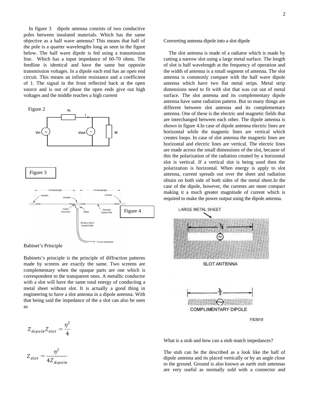
2In figure 3 dipole antenna consists of two conductivepoles between insulated materials. Which has the sameobjective as a half wave antenna? This means that half ofthe pole is a quarter wavelengths long as seen in the figurebelow. The half wave dipole is fed using a transmissionline. Which has a input impedance of 60-70 ohms. Thefeedline is identical and have the same but oppositetransmission voltages. In a dipole each end has an open endcircuit. This means an infinite resistance and a coefficientof 1. The signal in the front reflected back at the opensource and is out of phase the open ends give out highvoltages and the middle reaches a high current Babinet’s Principle Babinets’s principle is the principle of diffraction patternsmade by screens are exactly the same. Two screens arecomplementary when the opaque parts are one which iscorrespondent to the transparent ones. A metallic conductorwith a slot will have the same total energy of conducting ametal sheet without slot. It is actually a good thing inengineering to have a slot antenna in a dipole antenna. Withthat being said the impedance of the a slot can also be seenas Converting antenna dipole into a slot dipole The slot antenna is made of a radiator which is made bycutting a narrow slot using a large metal surface. The lengthof slot is half wavelength at the frequency of operation andthe width of antenna is a small segment of antenna. The slotantenna is commonly compare with the half wave dipoleantenna which have two flat metal strips. Metal stripdimensions need to fit with slot that was cut out of metalsurface. The slot antenna and its complementary dipoleantenna have same radiation pattern. But so many things aredifferent between slot antenna and its complementaryantenna. One of these is the electric and magnetic fields thatare interchanged between each other. The dipole antenna isshown in figure 4.In case of dipole antenna electric lines arehorizontal while the magnetic lines are vertical whichcreates loops. In case of slot antenna the magnetic lines arehorizontal and electric lines are vertical. The electric linesare made across the small dimensions of the slot, because ofthis the polarization of the radiation created by a horizontalslot is vertical. If a vertical slot is being used then thepolarization is horizontal. When energy is apply to slotantenna, current spreads out over the sheet and radiationobtain on both side of both sides of the metal sheet.In thecase of the dipole, however, the currents are more compactmaking it a much greater magnitude of current which isrequired to make the power output using the dipole antenna.What is a stub and how can a stub match impedances?The stub can be the described as a look like the half ofdipole antenna and its placed vertically or by an angle closeto the ground. Ground is also known as earth stub antennasare very useful as normally sold with a connector andFigure 2Figure 3Figure 4
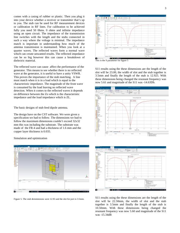
3comes with a casing of rubber or plastic. Then you plug itinto your device whether a receiver or transmitter that’s upto you. The stub can be used for RF measurement devicesor calibration in RF lines. For calibration to be achievedfully you need 50 0hms. 0 ohms and infinite impedanceusing an open circuit. The impedance of the transmissionline switches with the length and the stubs connected insuch a way where the voltage is minimal. The impedancematch is important in understanding how much of theantenna transmission is maintained. When you look at aquarter waves. The reflected waves form a normal wavewhich can create unwanted results. The reflected impedancecan be so big however this can cause a breakdown ofdielectric material.The reflected wave can cause affect the performance of thegenerator. This means to see whether there is no reflected wave at the generator, it is useful to have a unity VSWR. This proves the importance of the stub matching. A line must match when it is in a load which is equal to the characteristic impedance. The magnitude of the front wave is consumed by the load leaving no reflected wave detection. When it comes to the reflected waves it depends on difference between the Zo which is the characteristic impedance and the load impedance which is ZL.The basic designs of stub feed dipole antenna.The design have on the CST software. We were given a specification we had to follow. The dimensions we had to follow the maximum dimensions couldn’t exceed 32x32 mm this was including the substrate. The substrate was made of the FR-4 and had a thickness of 1.6 mm and the copper layer thickness is 0.035.Simulation and optimization Figure 5. The stub demminsions were 12.93 and the slot for port is 3.5mm.This is the S parameter for figure 5 S11 results using the these dimensions are the length of theslot will be 23.00, the width of slot and the stub together is3.5mm and finally the length of the stub is 12.925. Withthese dimensions being changed the resonant frequency wasnow 5.61 and magnitude of the S11 was -14.63Db.S11 results using the these dimensions are the length of theslot will be 22.50mm, the width of slot and the stubtogether is 3.5mm and finally the length of the stub is10.50mm. With these dimensions being changed theresonant frequency was now 5.60 and magnitude of the S11was -15.34dB
End of preview
Want to access all the pages? Upload your documents or become a member.
Related Documents
Interim Report of Ammar Ghazallg...
|6
|2416
|325
FM Radio Repeater Design for Long Range Communicationlg...
|11
|1391
|98
COMP 101 - Wireless Networking Technologies Reportlg...
|11
|1821
|81