Internetworking with TCP/IP: Network Setup and Services Configuration
VerifiedAdded on 2020/05/28
|22
|1535
|134
Practical Assignment
AI Summary
This document presents a comprehensive solution for a TCP/IP internetworking assignment, detailing the configuration of a network and its various services. The assignment begins with a network diagram and proceeds to configure PCs, a web server, a DHCP server, and a DNS server. Router configurations are meticulously outlined, including interface setups and routing protocols. The document further demonstrates the functionality of the network through ping tests, traceroute commands, and the configuration and testing of DHCP, web, DNS, and firewall services. Screenshots are provided to illustrate each step, offering a clear and practical guide to network setup and service implementation. The solution covers all aspects of the assignment, from basic network setup to advanced service configurations, providing a complete and practical understanding of TCP/IP internetworking concepts and their implementation.
Running head: INTERNETWORKING WITH TCP/IP
Internetworking with TCP/IP
Name of the Student
Name of the University
Author’s Note
Internetworking with TCP/IP
Name of the Student
Name of the University
Author’s Note
Paraphrase This Document
Need a fresh take? Get an instant paraphrase of this document with our AI Paraphraser
1
INTERNETWORKING WITH TCP/IP
Table of Contents
Task 1 - Setting up a Network.............................................................................................2
1. Network Diagram........................................................................................................2
2. Configuration of the PC...............................................................................................2
3. Configuration of the Server.........................................................................................4
4. Configuration of the Router interfaces........................................................................7
5. Configuration of the routing on the routers...............................................................10
6. Pinging own network interface on the client PC.......................................................12
7. Pinging local router gateway interface on the Client PC...........................................13
8. Pinging Remote Router Interface on the Client PC...................................................14
9. Using traceroute command from client to server......................................................15
Task 2 - Configuring Network Services............................................................................16
1. DHCP Configuration.................................................................................................16
2. WEB Server Configuration........................................................................................17
3. DNS Configuration....................................................................................................18
4. Firewall Configuration...............................................................................................19
Bibliography......................................................................................................................21
2
INTERNETWORKING WITH TCP/IP
Task 1 - Setting up a Network
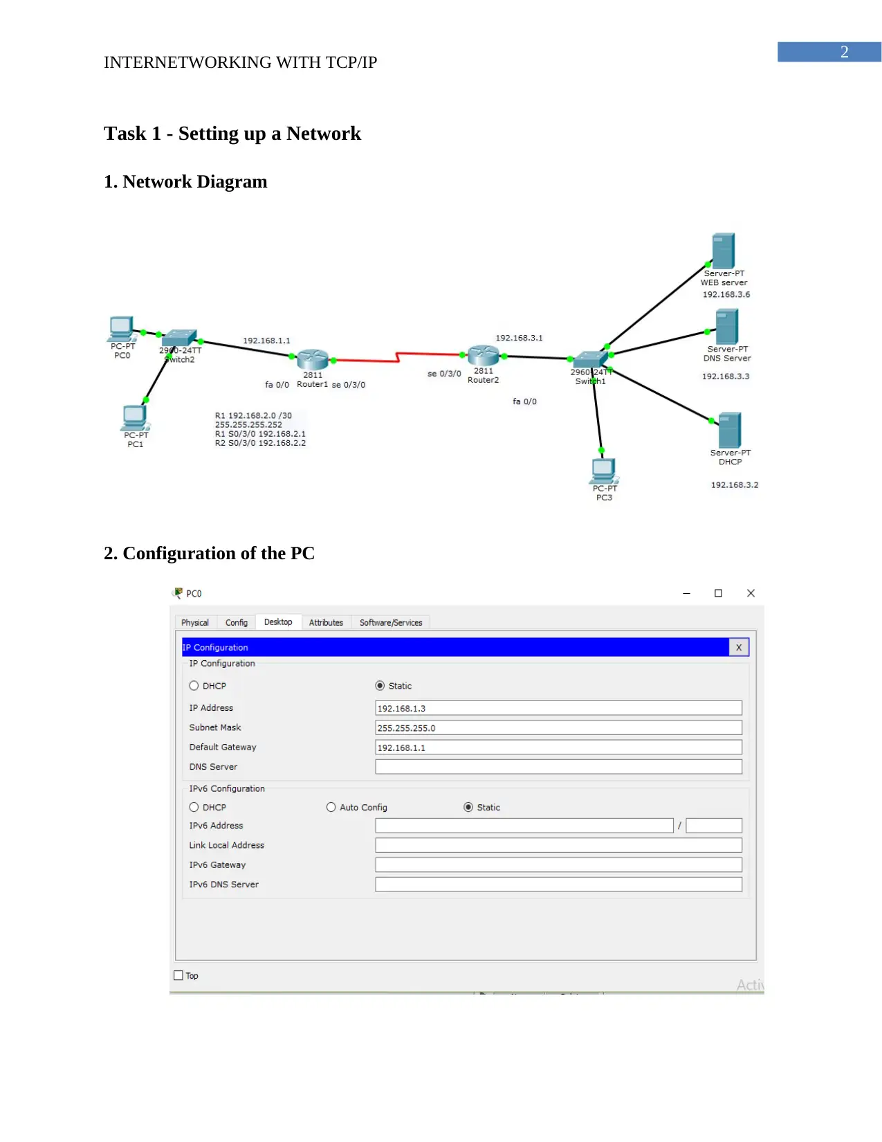
1. Network Diagram
2. Configuration of the PC
INTERNETWORKING WITH TCP/IP
Task 1 - Setting up a Network
1. Network Diagram
2. Configuration of the PC
⊘ This is a preview!⊘
Do you want full access?
Subscribe today to unlock all pages.

Trusted by 1+ million students worldwide
3
INTERNETWORKING WITH TCP/IP
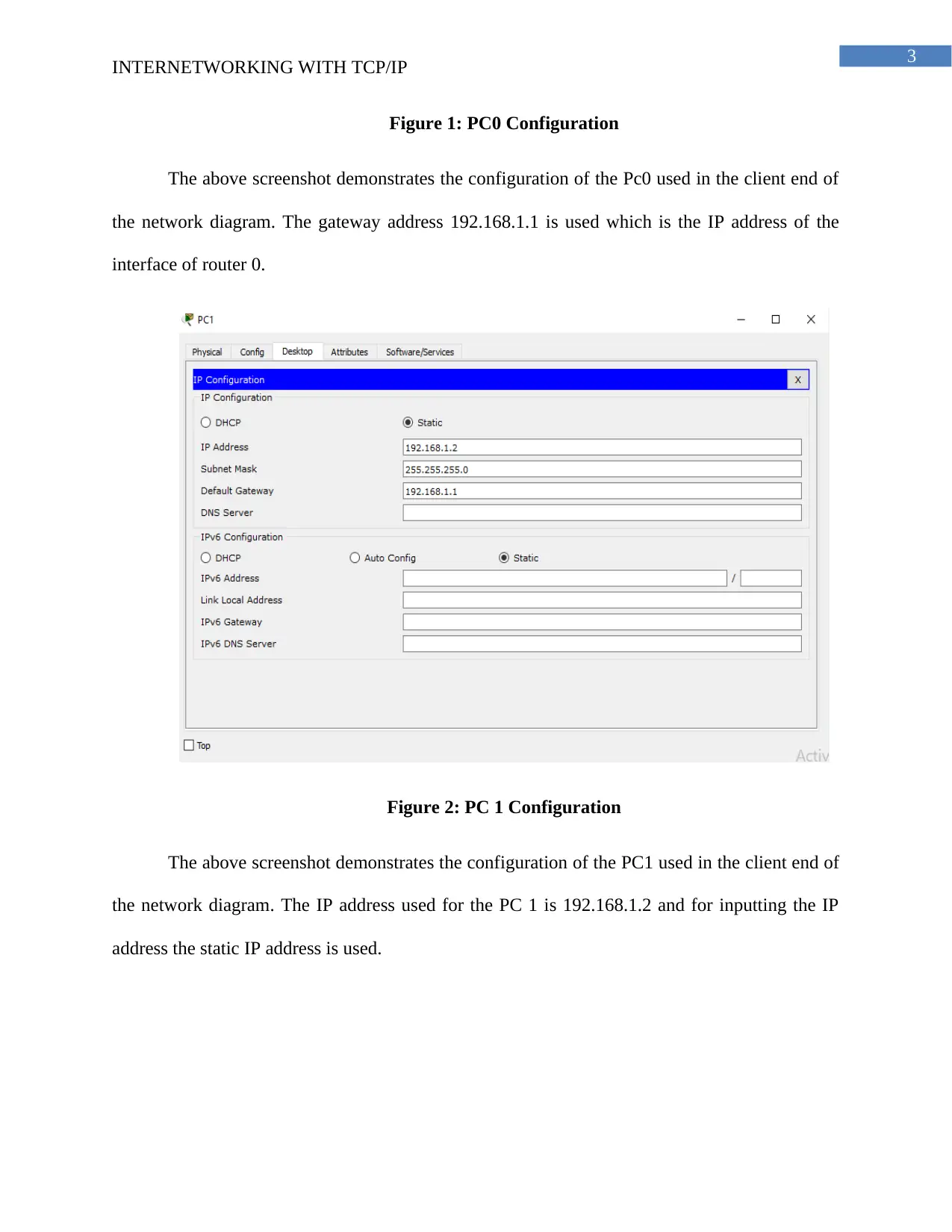
Figure 1: PC0 Configuration
The above screenshot demonstrates the configuration of the Pc0 used in the client end of
the network diagram. The gateway address 192.168.1.1 is used which is the IP address of the
interface of router 0.
Figure 2: PC 1 Configuration
The above screenshot demonstrates the configuration of the PC1 used in the client end of
the network diagram. The IP address used for the PC 1 is 192.168.1.2 and for inputting the IP
address the static IP address is used.
Paraphrase This Document
Need a fresh take? Get an instant paraphrase of this document with our AI Paraphraser
4
INTERNETWORKING WITH TCP/IP
3. Configuration of the Server
WEB Server
Figure 3: Web server configuration
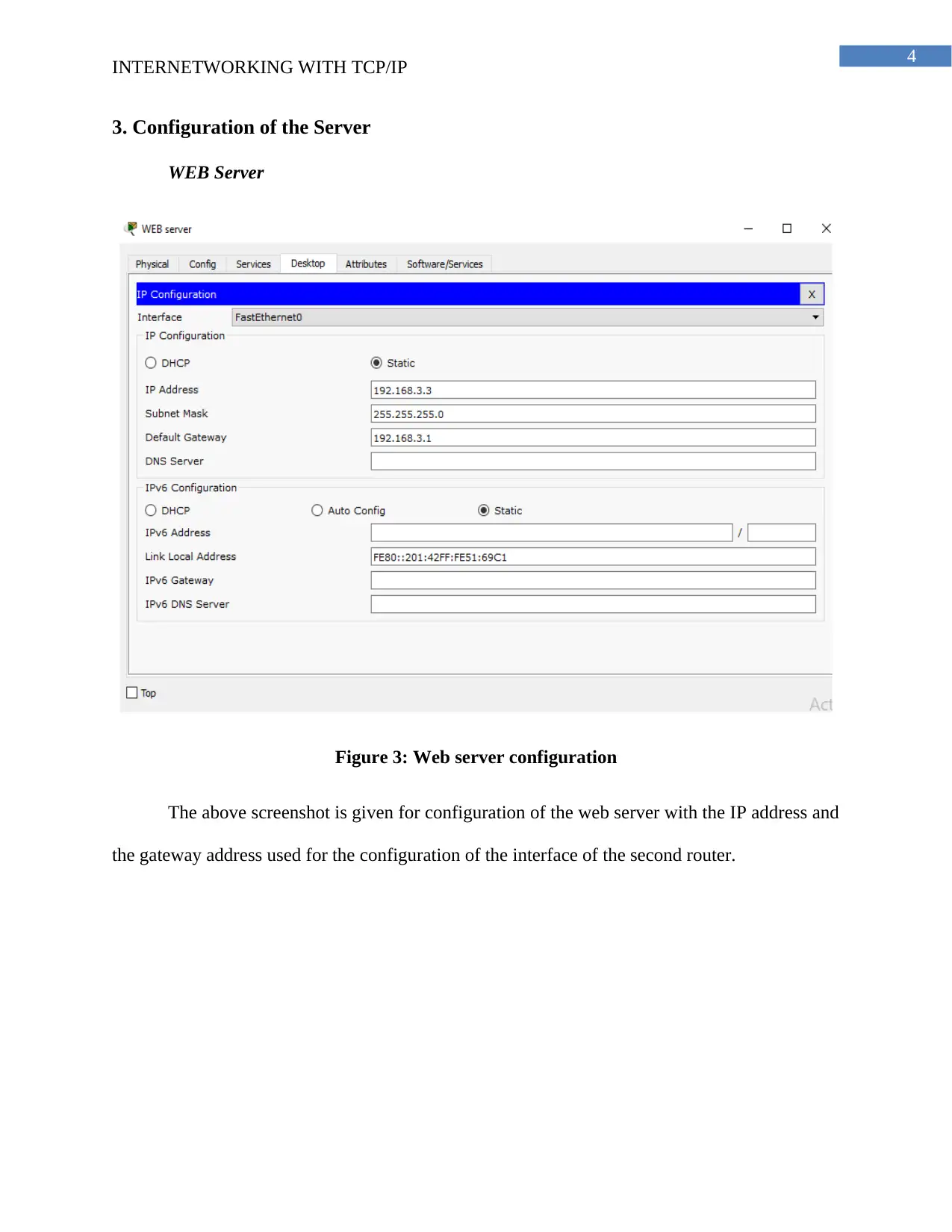
The above screenshot is given for configuration of the web server with the IP address and
the gateway address used for the configuration of the interface of the second router.
INTERNETWORKING WITH TCP/IP
3. Configuration of the Server
WEB Server
Figure 3: Web server configuration
The above screenshot is given for configuration of the web server with the IP address and
the gateway address used for the configuration of the interface of the second router.
5
INTERNETWORKING WITH TCP/IP
DHCP Server
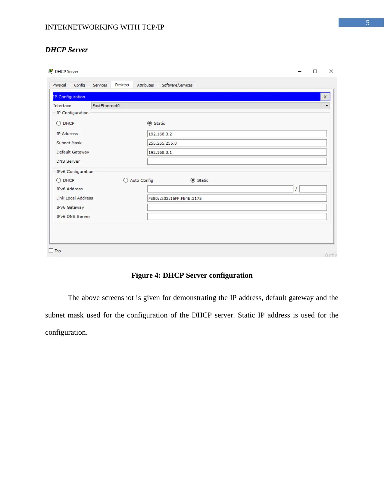
Figure 4: DHCP Server configuration
The above screenshot is given for demonstrating the IP address, default gateway and the
subnet mask used for the configuration of the DHCP server. Static IP address is used for the
configuration.
INTERNETWORKING WITH TCP/IP
DHCP Server
Figure 4: DHCP Server configuration
The above screenshot is given for demonstrating the IP address, default gateway and the
subnet mask used for the configuration of the DHCP server. Static IP address is used for the
configuration.
⊘ This is a preview!⊘
Do you want full access?
Subscribe today to unlock all pages.

Trusted by 1+ million students worldwide
6
INTERNETWORKING WITH TCP/IP
DNS Server
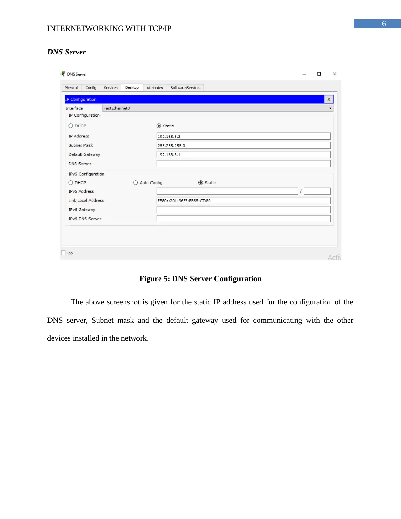
Figure 5: DNS Server Configuration
The above screenshot is given for the static IP address used for the configuration of the
DNS server, Subnet mask and the default gateway used for communicating with the other
devices installed in the network.
INTERNETWORKING WITH TCP/IP
DNS Server
Figure 5: DNS Server Configuration
The above screenshot is given for the static IP address used for the configuration of the
DNS server, Subnet mask and the default gateway used for communicating with the other
devices installed in the network.
Paraphrase This Document
Need a fresh take? Get an instant paraphrase of this document with our AI Paraphraser
7
INTERNETWORKING WITH TCP/IP
4. Configuration of the Router interfaces
Router 1 Configuration
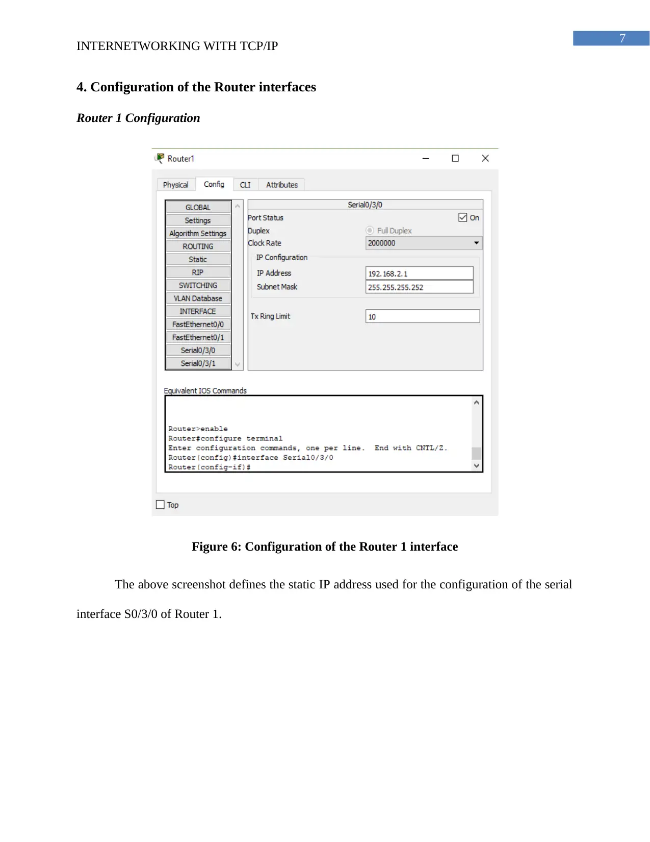
Figure 6: Configuration of the Router 1 interface
The above screenshot defines the static IP address used for the configuration of the serial
interface S0/3/0 of Router 1.
INTERNETWORKING WITH TCP/IP
4. Configuration of the Router interfaces
Router 1 Configuration
Figure 6: Configuration of the Router 1 interface
The above screenshot defines the static IP address used for the configuration of the serial
interface S0/3/0 of Router 1.
8
INTERNETWORKING WITH TCP/IP
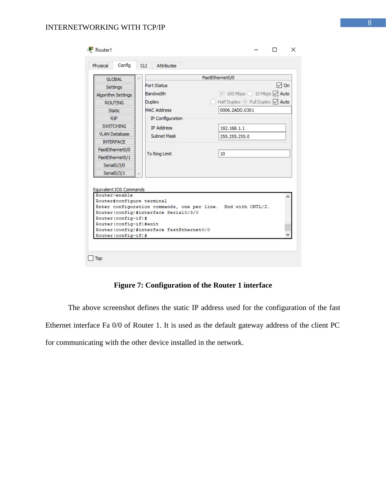
Figure 7: Configuration of the Router 1 interface
The above screenshot defines the static IP address used for the configuration of the fast
Ethernet interface Fa 0/0 of Router 1. It is used as the default gateway address of the client PC
for communicating with the other device installed in the network.
⊘ This is a preview!⊘
Do you want full access?
Subscribe today to unlock all pages.

Trusted by 1+ million students worldwide
9
INTERNETWORKING WITH TCP/IP
Router 2
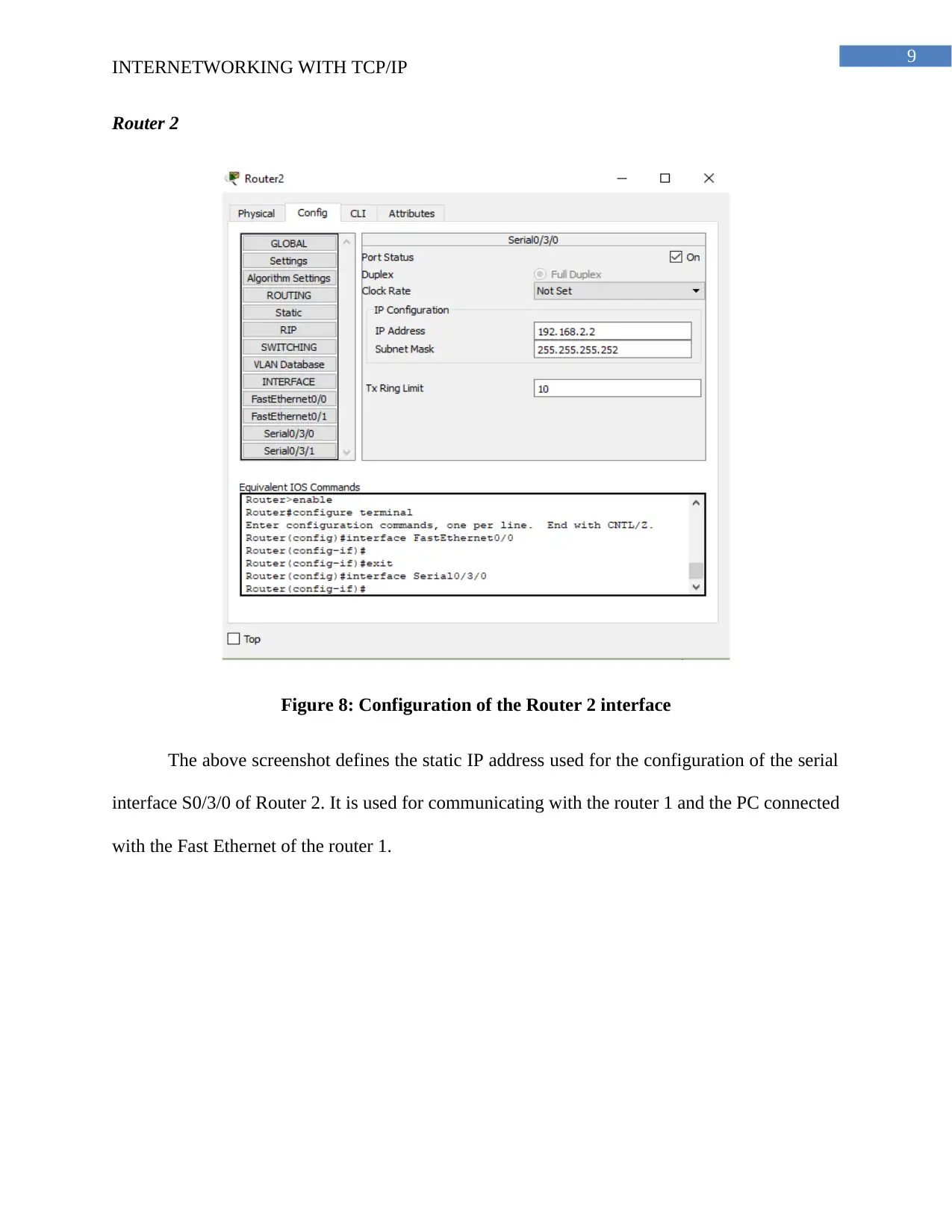
Figure 8: Configuration of the Router 2 interface
The above screenshot defines the static IP address used for the configuration of the serial
interface S0/3/0 of Router 2. It is used for communicating with the router 1 and the PC connected
with the Fast Ethernet of the router 1.
Paraphrase This Document
Need a fresh take? Get an instant paraphrase of this document with our AI Paraphraser
10
INTERNETWORKING WITH TCP/IP
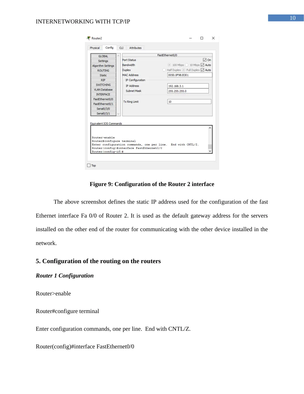
Figure 9: Configuration of the Router 2 interface
The above screenshot defines the static IP address used for the configuration of the fast
Ethernet interface Fa 0/0 of Router 2. It is used as the default gateway address for the servers
installed on the other end of the router for communicating with the other device installed in the
network.
5. Configuration of the routing on the routers
Router 1 Configuration
Router>enable
Router#configure terminal
Enter configuration commands, one per line. End with CNTL/Z.
Router(config)#interface FastEthernet0/0
11
INTERNETWORKING WITH TCP/IP
Router(config-if)#ip address 192.168.1.1 255.255.255.0
Router(config-if)#
Router(config-if)#exit
Router(config)#interface Serial0/3/0
Router(config-if)#ip address 192.168.2.1 255.255.255.252
Router(config-if)#exit
Router(config)#ip route 192.168.3.0 255.255.255.0 192.168.2.2
Router(config)#
%LINEPROTO-5-UPDOWN: Line protocol on Interface FastEthernet0/0, changed state to down
Router 2 Configuration
Router>enable
Router#configure terminal
Enter configuration commands, one per line. End with CNTL/Z.
Router(config)#interface Serial0/3/0
Router(config-if)#ip address 192.168.2.2 255.255.255.252
Router(config-if)#
Router(config-if)#exit
Router(config)#interface FastEthernet0/0
⊘ This is a preview!⊘
Do you want full access?
Subscribe today to unlock all pages.

Trusted by 1+ million students worldwide
1 out of 22
Related Documents
Your All-in-One AI-Powered Toolkit for Academic Success.
+13062052269
info@desklib.com
Available 24*7 on WhatsApp / Email
![[object Object]](/_next/static/media/star-bottom.7253800d.svg)
Unlock your academic potential
Copyright © 2020–2026 A2Z Services. All Rights Reserved. Developed and managed by ZUCOL.


