Analysis of Wind Tunnel Experiment and CFD Simulation Report
VerifiedAdded on 2019/09/30
|8
|1931
|316
Report
AI Summary
This report provides an in-depth analysis of a wind tunnel experiment and its corresponding computational fluid dynamics (CFD) simulation. It details the experimental setup, including the use of a digital manometer and pilot tubes, and discusses the concepts of steady and unsteady flow, compressible and incompressible flow, and laminar versus turbulent flow. The report calculates the Reynolds number to characterize the flow regime and examines the boundary layer's impact on the flow. Furthermore, it describes the CFD simulation process using ANSYS, including CAD model creation, meshing, and the application of boundary conditions to obtain velocity profiles and pressure contours. The study aims to determine flow patterns within the wind tunnel, offering valuable insights for future aerodynamic research, such as testing aerodynamic components like aerofoils and F-1 racing car components.
Introduction:
After the project proposal of the wind tunnel experiment and CFD, this report will provide some
more information about how the data was recorded from a wind tunnel experiment and CFD.
Some investigations need to be considered in order to analyze the results.
As project proposal of the wind tunnel experiment using CFD simulation tool, the report
article demonstrates the detail discussion for wind tunnel experiment and computational fluid
dynamic approach. The article demonstrates the analysis approach in order to find results. As
discussed in a previous semester for wind tunnel working methodology, the next step is to
perform testing and determine to streamline wise flow development and a different pattern of
flow while perform testing. The aim of this study to evaluate streamline through a side of the
tunnel and enhance significance flow in three dimensions. The flow of fluid could be compared
with the theoretical aspect of model simulate using fluent approach through computational fluid
dynamic tool using ANSYS work batch computer application.
The aim of this research is to determine the flow patterns within wind tunnel to obtain
usefulness for future research about aerodynamic and behavior of flow patterns. If the research
will successful as given objective, the Victoria University team may able to test aerodynamic
profile component such as aerofoil, F-1 racing car component design etc. in order to develop
actual environment, the test data taken for the experiment was almost same. The experimental
approach uses an actual speed of a racing car and component size, feature and property were
taken as 1:1 ratio. For simplicity, the flow velocity needs to manage in order to maintain the
Raynolds number (Wah Yen,2014).
1 | P a g e
Paraphrase This Document
Need a fresh take? Get an instant paraphrase of this document with our AI Paraphraser
Theoretical approach:
In fluid dynamics, the fluid behavior change with a change in external applied force, velocity
and relevant parameters. According to the study, the steady state of flow is defined as fluid
dynamic conditions will not change with respect to time. Whether the fluid property will
change flow with respect to time, the flow of fluid become unsteady.
In an experiment of a wind tunnel, the digital manometer place and pilot tube provide at each
location. The result indicates the flow of fluid steady as the fluid property was not considerable
change with respect to time.
Compressible and incompressible flow:
If the density of the fluid does not change with a different condition, the flow of fluid known as
incompressible flow e.g. flow of air at low speeds. The fluid flow density changes at the
different condition, the flow known as compressible flow. The air flow is considered as
incompressible at low speed with an assumption of a speed of sound does not react to the
situation.
The speed of sound changes magnitude as traveled through a different medium. The speed of
sound is higher in water medium compare to air medium. In order to identify the actual condition,
the flow of air assume incompressible and obtain Mach number.
The Mach number is the dimensionless parameter which found from the following equation.
Mac h Number= Speed of Sound
speed of object
2 | P a g e
In a wind tunnel experiment, it was found that the maximum flow of air around 20mrs and
obtaining Mach number from this parameters as 0.06. The Mach number indicates that the flow of
fluid is incompressible within the wind tunnel.
Laminar flow and turbulence flow:
The flow of fluid or air can categorize in laminar flow or turbulent flow in wind tunnel flow
experiment. The laminar flow found when the flow of fluid is parallel with two layers. The
velocity magnitude change from a centerline of a tube to an extreme position of tube ends. We can
assume that velocity remains zero at the stationary condition and reach the maximum as flow
passed away from the centerline. The magnitude varies from zero to maximum (Breuer, 2018).
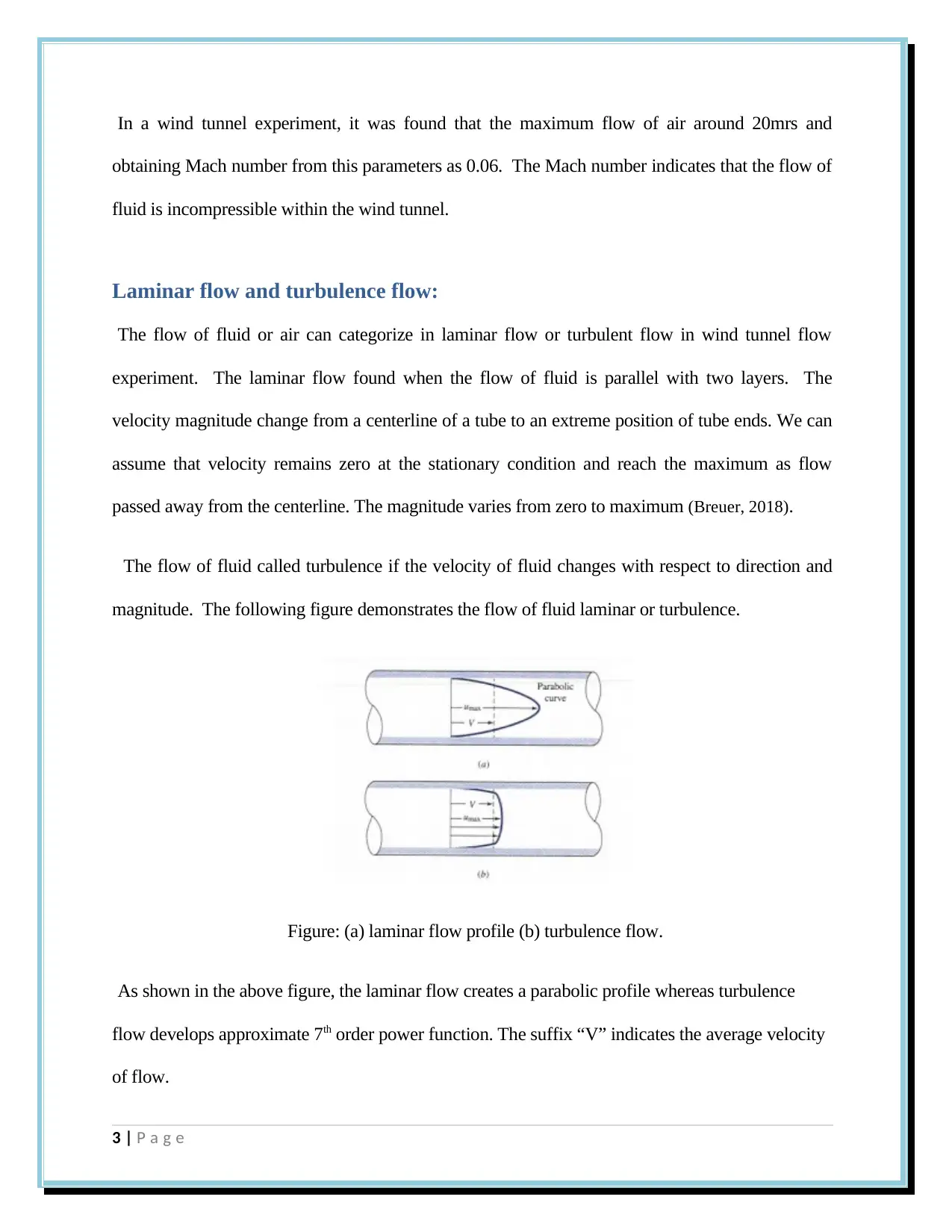
The flow of fluid called turbulence if the velocity of fluid changes with respect to direction and
magnitude. The following figure demonstrates the flow of fluid laminar or turbulence.
Figure: (a) laminar flow profile (b) turbulence flow.
As shown in the above figure, the laminar flow creates a parabolic profile whereas turbulence
flow develops approximate 7th order power function. The suffix “V” indicates the average velocity
of flow.
3 | P a g e
⊘ This is a preview!⊘
Do you want full access?
Subscribe today to unlock all pages.

Trusted by 1+ million students worldwide
Considering the flow of fluid in wind tunnel velocity profiles, that found the partial area of
data collection within the wind tunnel. the flow developed demonstrates the characteristics
function of turbulent flow. In order to find an actual result, we are comparing the result with
Reynolds number that needs to calculated and compared with results.
The Reynolds number is the dimensionless parameters used to ensure the flow is
turbulence or laminar flow. The Reynolds number is defined as the ratio of inertia
force to the viscous force. The Reynolds number obtains from the following
equation.
ℜ= ρUd h
μ
ρ=fluid density ( kg
m 3 )
U =average velocity , m
s
d h=h ydrualic diameter ,m
μ=dynamic viscosity , m2
s
The Reynolds number is defined as the flow as laminar or turbulent as provide
following relation with numbers.
If Reynolds number value less than 2300 the flow is laminar, Reynolds number value
more than 2300 and less than 4300, the flow is transient. If the Reynolds number
value more than 4000 the flow is turbulence.
The wind tunnel experiment has rectangular duct section in a stand of circular
section. The relation is providing as follows:
dh= 4 ab
2 ( a+b )
4 | P a g e
Paraphrase This Document
Need a fresh take? Get an instant paraphrase of this document with our AI Paraphraser
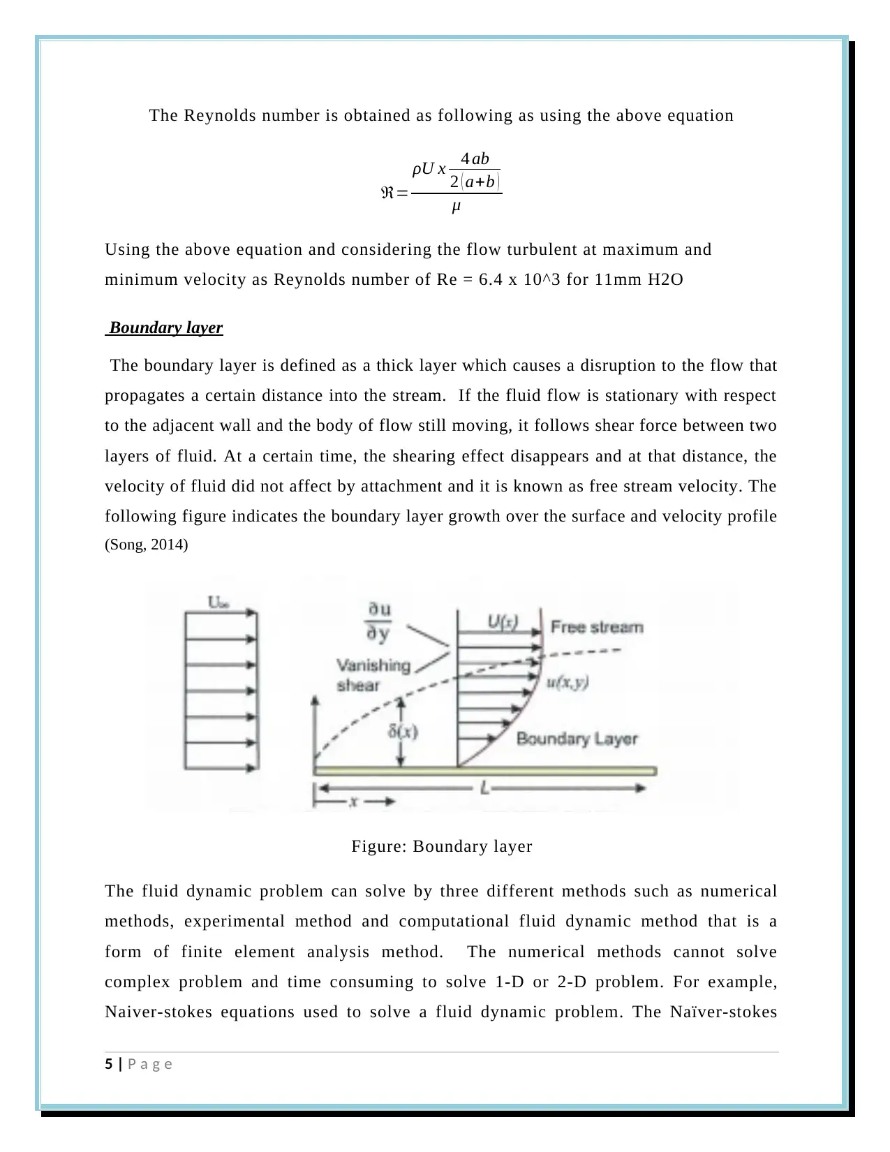
The Reynolds number is obtained as following as using the above equation
ℜ=
ρU x 4 ab
2 ( a+b )
μ
Using the above equation and considering the flow turbulent at maximum and
minimum velocity as Reynolds number of Re = 6.4 x 10^3 for 11mm H2O
Boundary layer
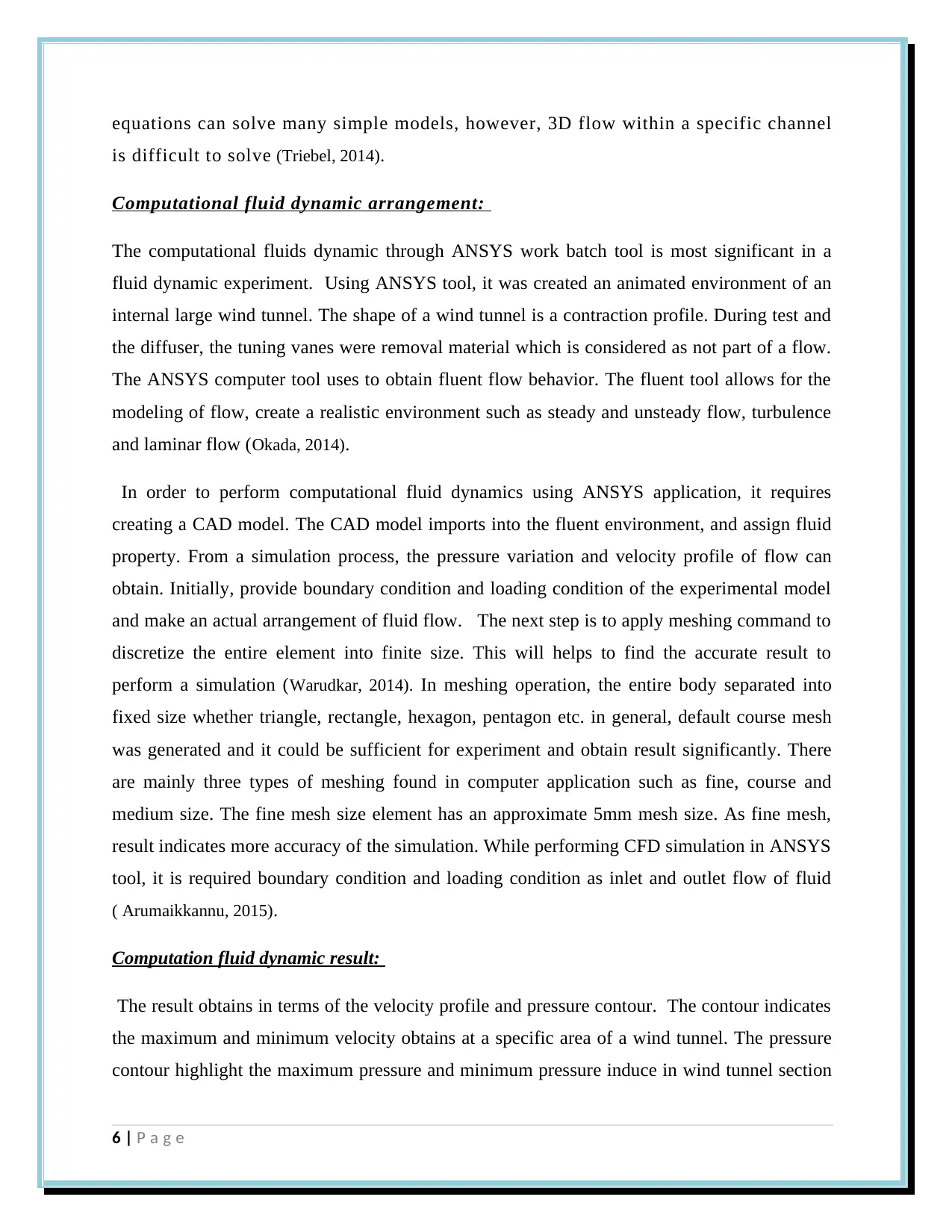
The boundary layer is defined as a thick layer which causes a disruption to the flow that
propagates a certain distance into the stream. If the fluid flow is stationary with respect
to the adjacent wall and the body of flow still moving, it follows shear force between two
layers of fluid. At a certain time, the shearing effect disappears and at that distance, the
velocity of fluid did not affect by attachment and it is known as free stream velocity. The
following figure indicates the boundary layer growth over the surface and velocity profile
(Song, 2014)
Figure: Boundary layer
The fluid dynamic problem can solve by three different methods such as numerical
methods, experimental method and computational fluid dynamic method that is a
form of finite element analysis method. The numerical methods cannot solve
complex problem and time consuming to solve 1-D or 2-D problem. For example,
Naiver-stokes equations used to solve a fluid dynamic problem. The Naïver-stokes
5 | P a g e
equations can solve many simple models, however, 3D flow within a specific channel
is difficult to solve (Triebel, 2014).
Computational fluid dynamic arrangement:
The computational fluids dynamic through ANSYS work batch tool is most significant in a
fluid dynamic experiment. Using ANSYS tool, it was created an animated environment of an
internal large wind tunnel. The shape of a wind tunnel is a contraction profile. During test and
the diffuser, the tuning vanes were removal material which is considered as not part of a flow.
The ANSYS computer tool uses to obtain fluent flow behavior. The fluent tool allows for the
modeling of flow, create a realistic environment such as steady and unsteady flow, turbulence
and laminar flow (Okada, 2014).
In order to perform computational fluid dynamics using ANSYS application, it requires
creating a CAD model. The CAD model imports into the fluent environment, and assign fluid
property. From a simulation process, the pressure variation and velocity profile of flow can
obtain. Initially, provide boundary condition and loading condition of the experimental model
and make an actual arrangement of fluid flow. The next step is to apply meshing command to
discretize the entire element into finite size. This will helps to find the accurate result to
perform a simulation (Warudkar, 2014). In meshing operation, the entire body separated into
fixed size whether triangle, rectangle, hexagon, pentagon etc. in general, default course mesh
was generated and it could be sufficient for experiment and obtain result significantly. There
are mainly three types of meshing found in computer application such as fine, course and
medium size. The fine mesh size element has an approximate 5mm mesh size. As fine mesh,
result indicates more accuracy of the simulation. While performing CFD simulation in ANSYS
tool, it is required boundary condition and loading condition as inlet and outlet flow of fluid
( Arumaikkannu, 2015).
Computation fluid dynamic result:
The result obtains in terms of the velocity profile and pressure contour. The contour indicates
the maximum and minimum velocity obtains at a specific area of a wind tunnel. The pressure
contour highlight the maximum pressure and minimum pressure induce in wind tunnel section
6 | P a g e
⊘ This is a preview!⊘
Do you want full access?
Subscribe today to unlock all pages.

Trusted by 1+ million students worldwide

and provide a suggestion that the pressure distribution affects the performance of a wind
tunnel. The maximum velocity found from the experiment.
References
Che Sidik, N., & Wah Yen, T. (2014). Reynolds Number–Strouhal Number Relationship for
Cylindrical Bluff Body with Variation of Aspect Ratio in High Reynolds Number. Jurnal
Teknologi, 69(3). doi: 10.11113/jt.v69.3309
Gao, F., Li, G., Hu, R., & Okada, H. (2014). Computational Fluid Dynamic Analysis of
Coronary Artery Stenting. International Journal Of Bioscience, Biochemistry, And
Bioinformatics, 4(3), 155-159. doi: 10.7763/ijbbb.2014.v4.330
Investigation of Laminar Flow of Fluid with One Porous Bounding Wall. (2016). International
Journal Of Science And Research (IJSR), 5(1), 261-267. doi: 10.21275/v5i1.nov152699
Begum, S., & Arumaikkannu, G. (2015). Computational fluid dynamic analysis and additive
manufacturing of customized bone scaffolds. Progress In Computational Fluid Dynamics, An
International Journal, 15(3), 197. doi: 10.1504/pcfd.2015.069590
Breuer, M. (2018). Effect of Inflow Turbulence on an Airfoil Flow with Laminar Separation
Bubble: An LES Study. Flow, Turbulence And Combustion, 101(2), 433-456. doi:
10.1007/s10494-017-9890-2
Cai, X., Huo, Q., Kang, L., & Song, Y. (2014). Equilibrium Atmospheric Boundary-Layer
Flow: Computational Fluid Dynamics Simulation with Balanced Forces. Boundary-Layer
Meteorology, 152(3), 349-366. doi: 10.1007/s10546-014-9928-0
S Muttalli, R., Agrawal, S., & Warudkar, H. (2014). CFD Simulation of Centrifugal Pump
Impeller Using ANSYS-CFX. International Journal Of Innovative Research In Science,
Engineering And Technology, 03(08), 15553-15561. doi: 10.15680/ijirset.2014.0308066
7 | P a g e
Paraphrase This Document
Need a fresh take? Get an instant paraphrase of this document with our AI Paraphraser

Triebel, H. (2014). Navier-Stokes equations, Haar wavelets, and Reynolds numbers.
Mathematische Nachrichten, 288(8-9), 1057-1072. doi: 10.1002/mana.201400080
8 | P a g e
Mathematische Nachrichten, 288(8-9), 1057-1072. doi: 10.1002/mana.201400080
8 | P a g e
1 out of 8
Related Documents
Your All-in-One AI-Powered Toolkit for Academic Success.
+13062052269
info@desklib.com
Available 24*7 on WhatsApp / Email
![[object Object]](/_next/static/media/star-bottom.7253800d.svg)
Unlock your academic potential
Copyright © 2020–2025 A2Z Services. All Rights Reserved. Developed and managed by ZUCOL.


