Hardware Simulation: Implementing Logic Gates (Mux, Demux) and More

Verified

Added on  2022/08/12

|29
|2518
|26
Practical Assignment
AI Summary
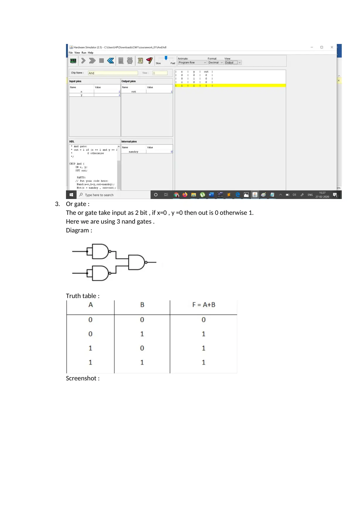
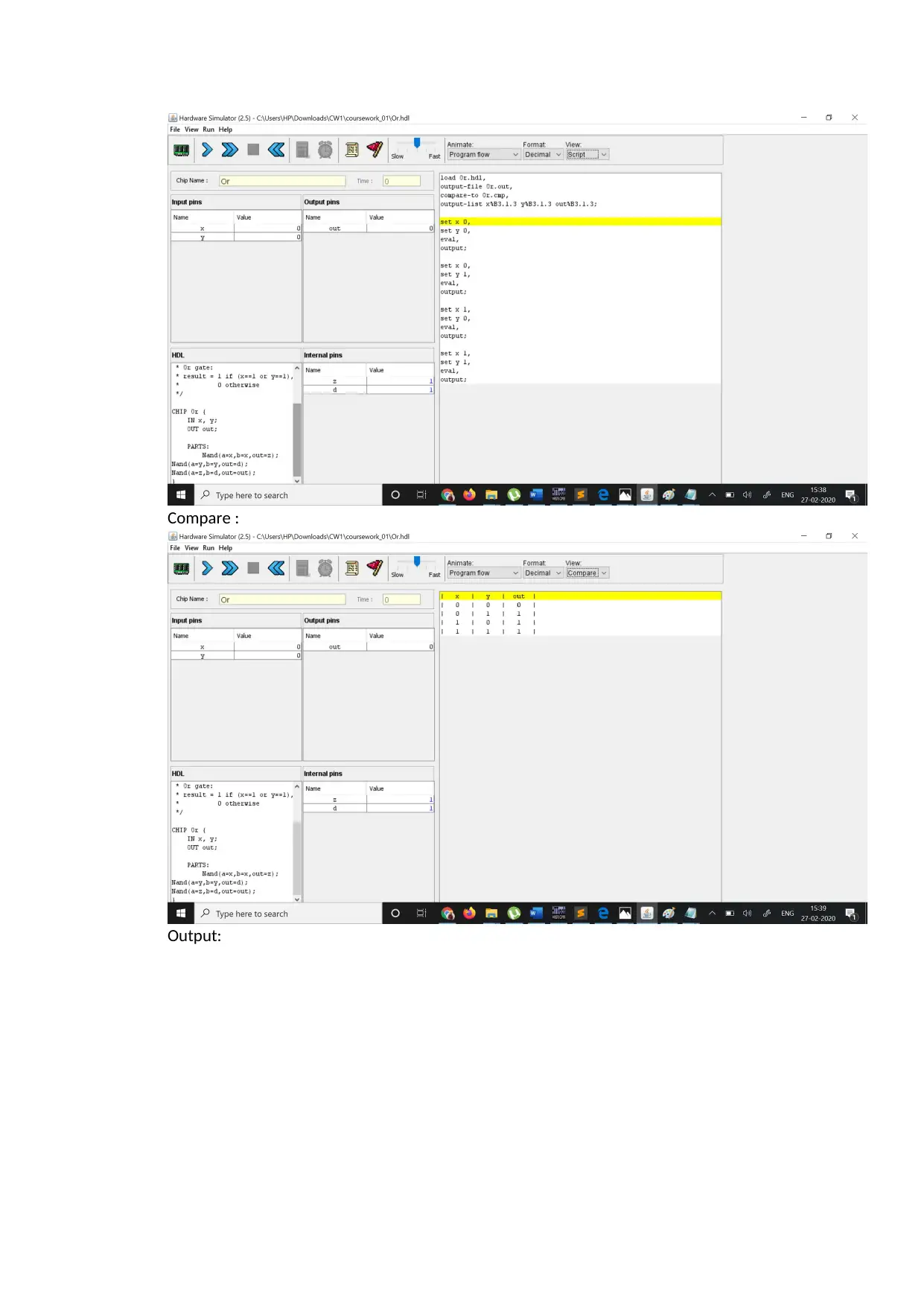
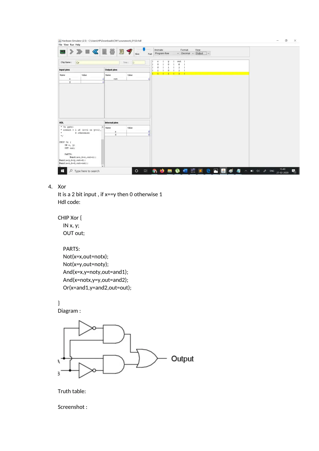
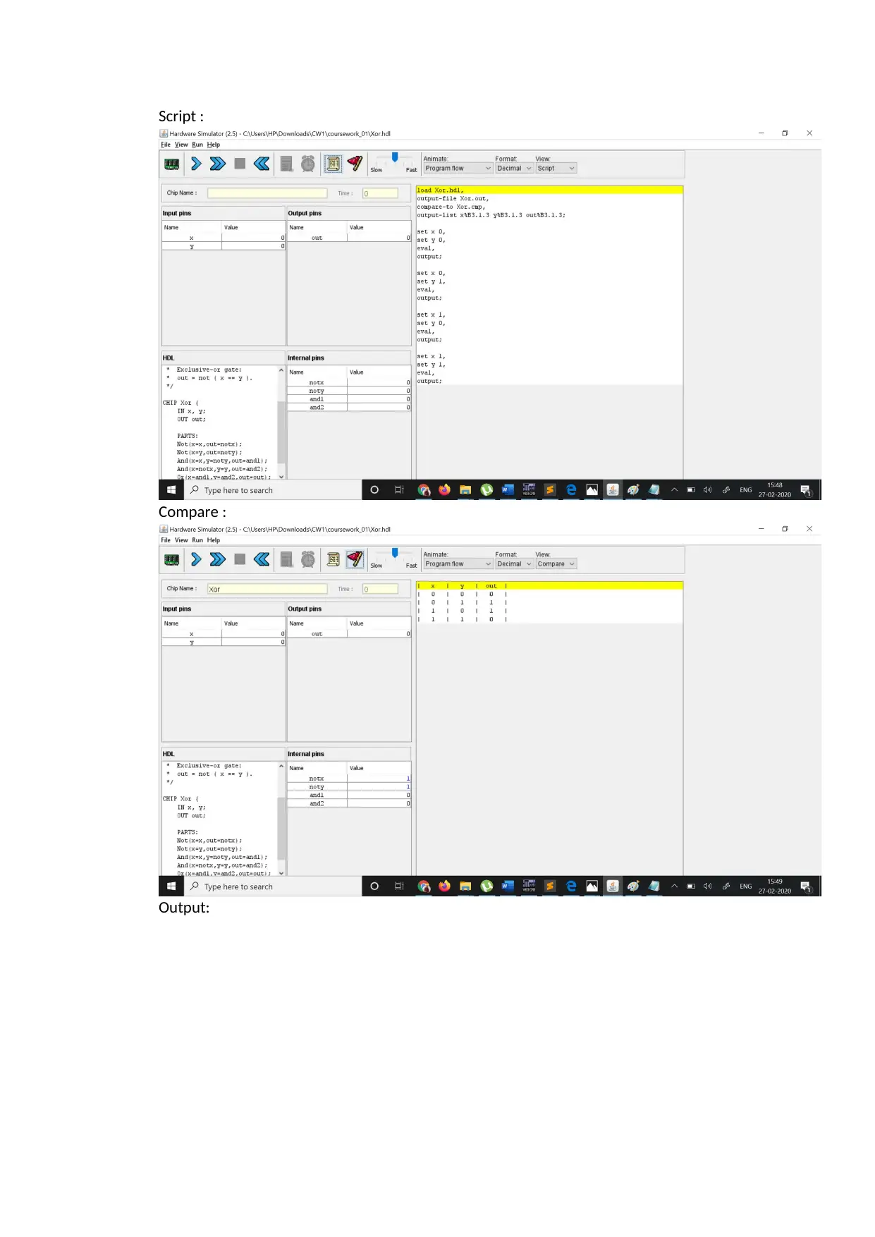
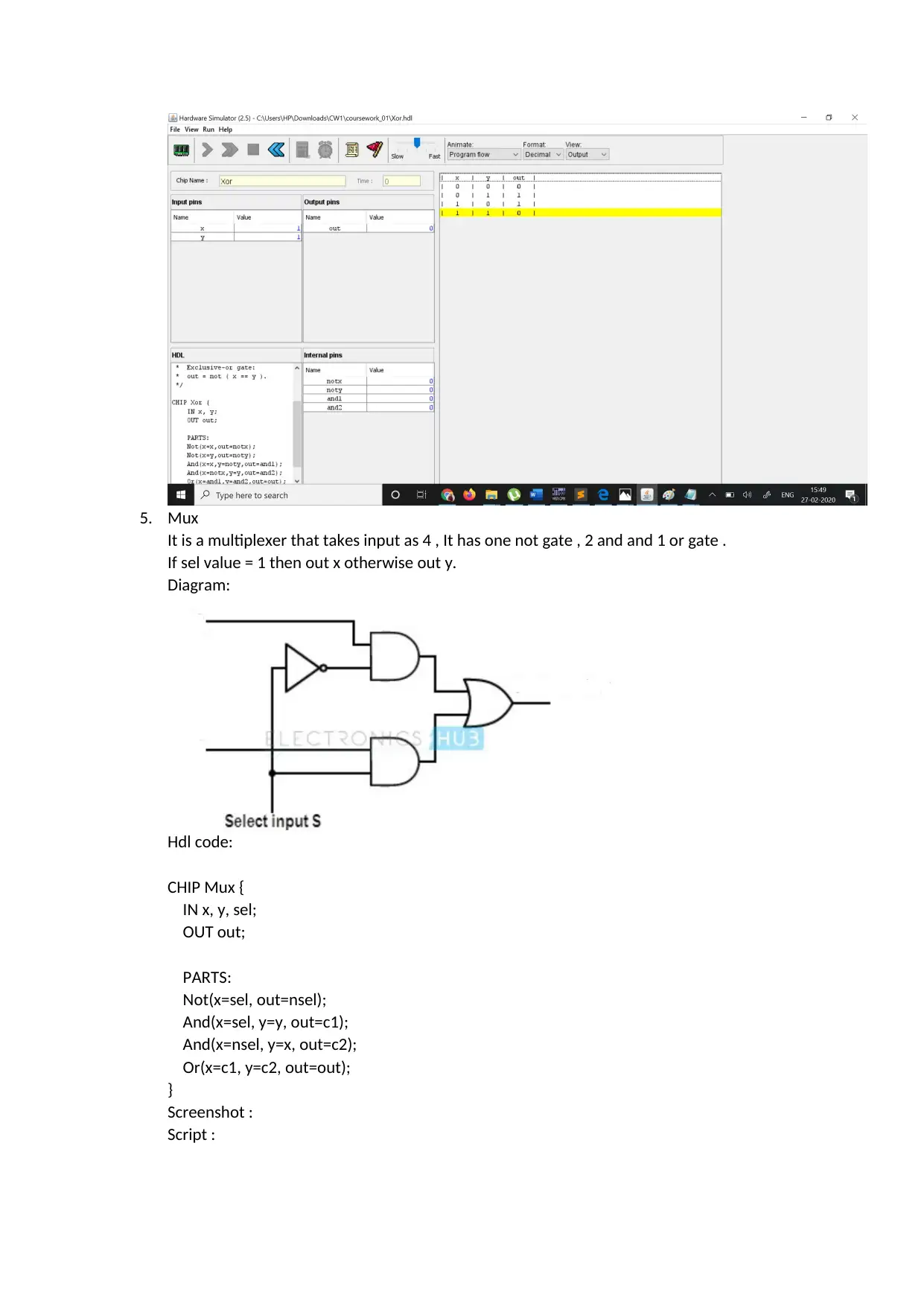
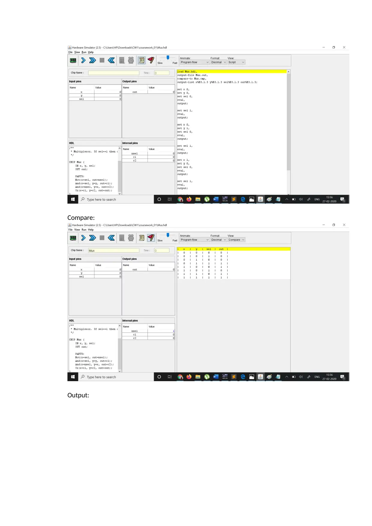
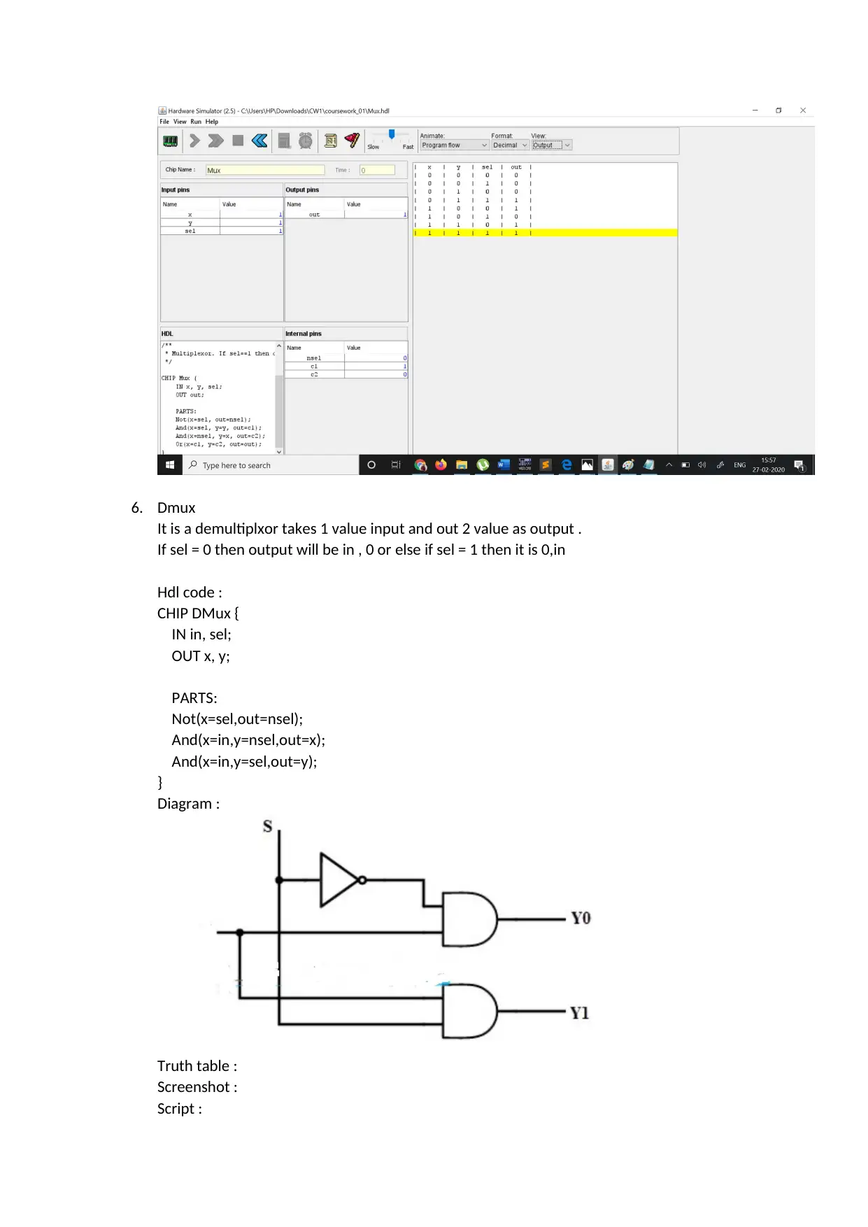
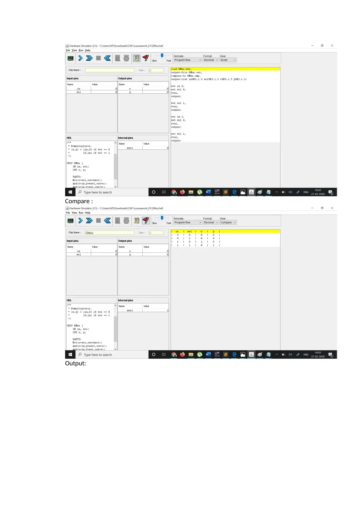
This assignment focuses on implementing various logic gates using a hardware simulator. The project begins with the basic gates like Not, And, Or, and Xor, demonstrating their functionality and truth tables within the .hdl (Hardware Description Language) files. The core of the assignment involves designing and simulating more complex circuits such as multiplexers (Mux) and demultiplexers (Demux), along with their 16-bit and 8-way variations, showing how these components are built using the fundamental gates. The .hdl files define the chip's structure, while .tst files contain scripts to test the chips, and .cmp files provide the expected outputs for comparison. The document illustrates the design process, including screenshots of the code, script execution, and comparison results, ensuring the correctness of each gate's implementation. The project culminates in the design and simulation of more intricate circuits like Or8way, Mux8Way16, DMux4Way, and DMux8Way, providing a comprehensive understanding of digital logic design and hardware simulation principles. The assignment showcases the practical application of logic gates in building complex digital circuits and how hardware simulators are used to verify their functionality.
Document Page
Introduction
This is a computer processor topic in which we test different type of logic gates. It uses Hardware
simulator to run the chips. Here we will be discussing about the universal gates and using them we
having created multiplexor, demultiplexer.
It consists of the 3 files - .hdl,.tst,.cmp
Designing of chips are not sufficient we need to write the chips in a way that computer can
understand. So we write the parts in .hdl(Hardware Description Language) then we load the script
which is present in .tst file then we compare the output to the .cmp file where already the truth
table are present and it matches the output file to .cmp file to check whether the parts written
in .hdl file is correct or not .
Purpose:
The purpose here is to convert the logic gates in the computer readable language using the
hardware stimulator which uses JVM as a complier. If it doesn’t found any type of file then it
searches it in its own directory.
Function :
1. Not gate :
The not gate take input x as 1 bit . if x = 0 then out is 1 , if x = 1 then out is 0 .
It inverts the value of the input .
Diagram :
Truth table:
We will implement the following Not gate in Hdl file and will compare the output :
Hdl file code :
CHIP Not {
IN x;
OUT out;
tabler-icon-diamond-filled.svg

Paraphrase This Document

Need a fresh take? Get an instant paraphrase of this document with our AI Paraphraser
Document Page
PARTS:
Nand(a=x,b=x,out=out);
}
Screenshot :
This contains the script part after loading script then we compare the output with .cmp file :
Output :
Document Page
2. And gate :
The and gate takes input as 2 bit . If input are x=1,y=1 then out is 1 otherwise 0.
Here we are using one nand and one or gate .
Diagram :
Truth table :
Hdl code :
CHIP And {
IN x, y;
OUT out;
PARTS:
// Put your code here:
Document Page
Nand(a=x,b=y,out=nandxy);
Not(x = nandxy , out=out);
}
Screenshot:
Script :
Compare :
Output :
tabler-icon-diamond-filled.svg

Paraphrase This Document

Need a fresh take? Get an instant paraphrase of this document with our AI Paraphraser
Document Page
3. Or gate :
The or gate take input as 2 bit , if x=0 , y =0 then out is 0 otherwise 1.
Here we are using 3 nand gates .
Diagram :
Truth table :
Screenshot :
Document Page
Compare :
Output:
Document Page
4. Xor
It is a 2 bit input , if x==y then 0 otherwise 1
Hdl code:
CHIP Xor {
IN x, y;
OUT out;
PARTS:
Not(x=x,out=notx);
Not(x=y,out=noty);
And(x=x,y=noty,out=and1);
And(x=notx,y=y,out=and2);
Or(x=and1,y=and2,out=out);
}
Diagram :
Truth table:
Screenshot :
tabler-icon-diamond-filled.svg

Paraphrase This Document

Need a fresh take? Get an instant paraphrase of this document with our AI Paraphraser
Document Page
Script :
Compare :
Output:
Document Page
5. Mux
It is a multiplexer that takes input as 4 , It has one not gate , 2 and and 1 or gate .
If sel value = 1 then out x otherwise out y.
Diagram:
Hdl code:
CHIP Mux {
IN x, y, sel;
OUT out;
PARTS:
Not(x=sel, out=nsel);
And(x=sel, y=y, out=c1);
And(x=nsel, y=x, out=c2);
Or(x=c1, y=c2, out=out);
}
Screenshot :
Script :
Document Page
Compare:
Output:
tabler-icon-diamond-filled.svg

Paraphrase This Document

Need a fresh take? Get an instant paraphrase of this document with our AI Paraphraser
Document Page
6. Dmux
It is a demultiplxor takes 1 value input and out 2 value as output .
If sel = 0 then output will be in , 0 or else if sel = 1 then it is 0,in
Hdl code :
CHIP DMux {
IN in, sel;
OUT x, y;
PARTS:
Not(x=sel,out=nsel);
And(x=in,y=nsel,out=x);
And(x=in,y=sel,out=y);
}
Diagram :
Truth table :
Screenshot :
Script :
Document Page
Compare :
Output:
chevron_up_icon
1 out of 29
circle_padding
hide_on_mobile
zoom_out_icon
[object Object]