ANSYS Fluent Application for Fluid Flow Simulation in Pipe and Heat Exchanger

Verified

Added on  2023/04/23

|10
|1334
|473
AI Summary
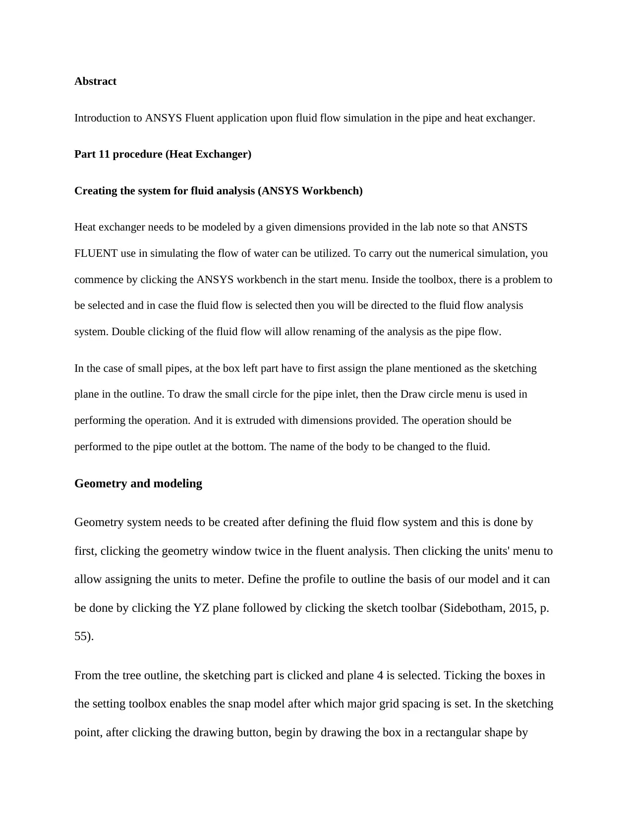
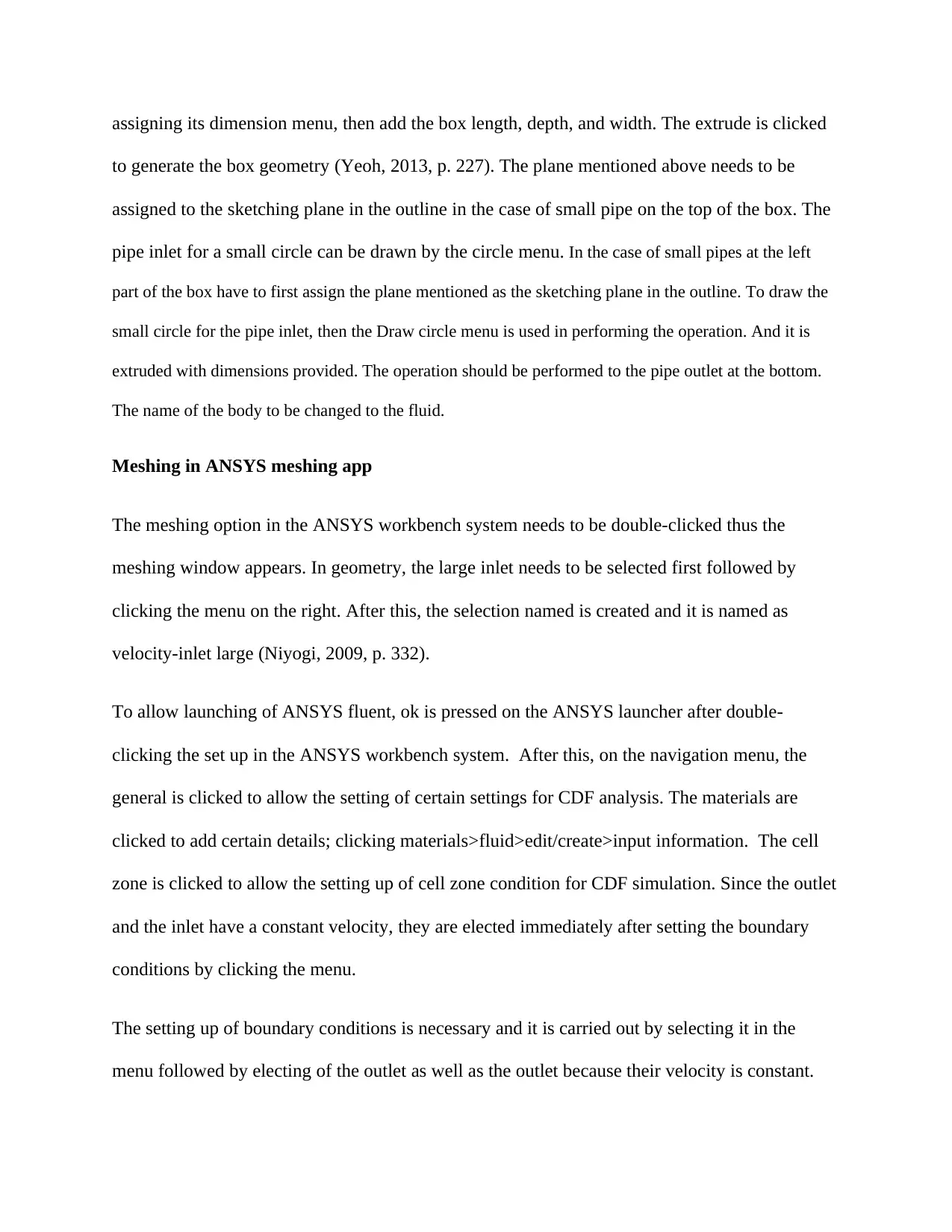
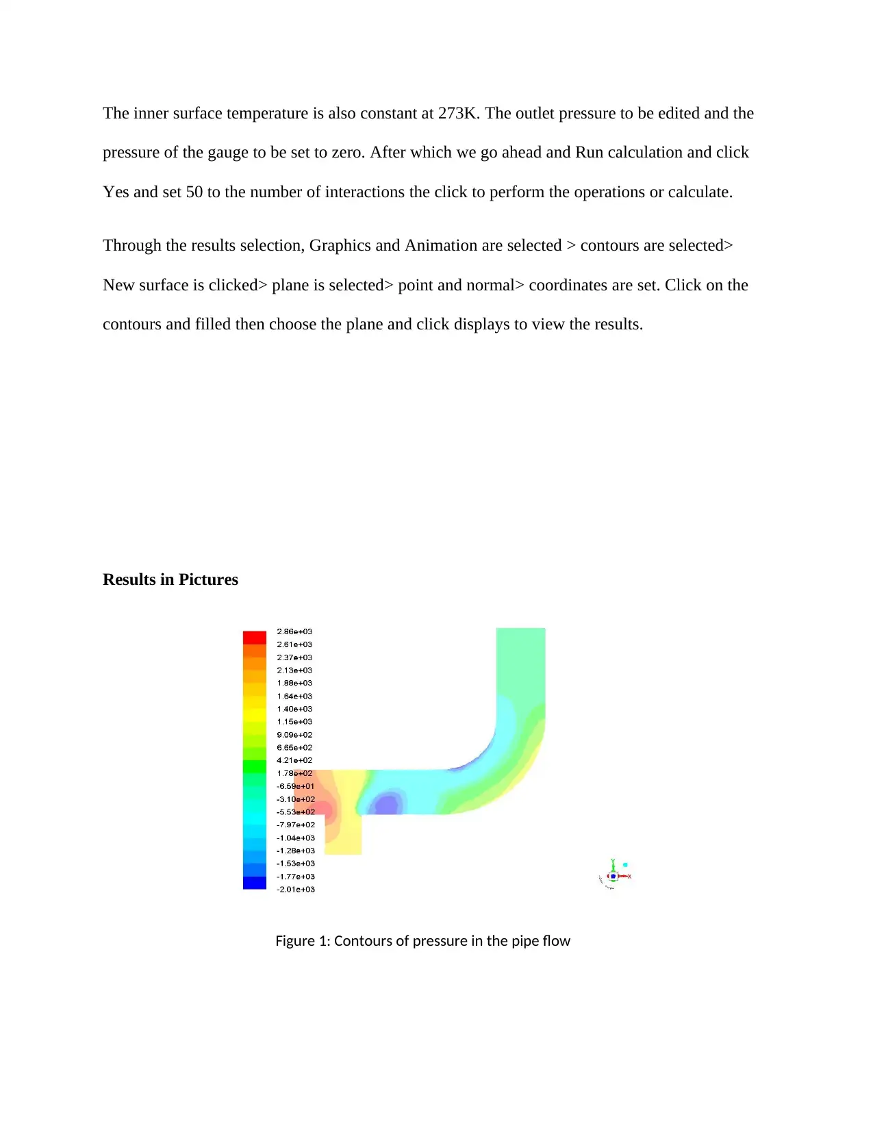
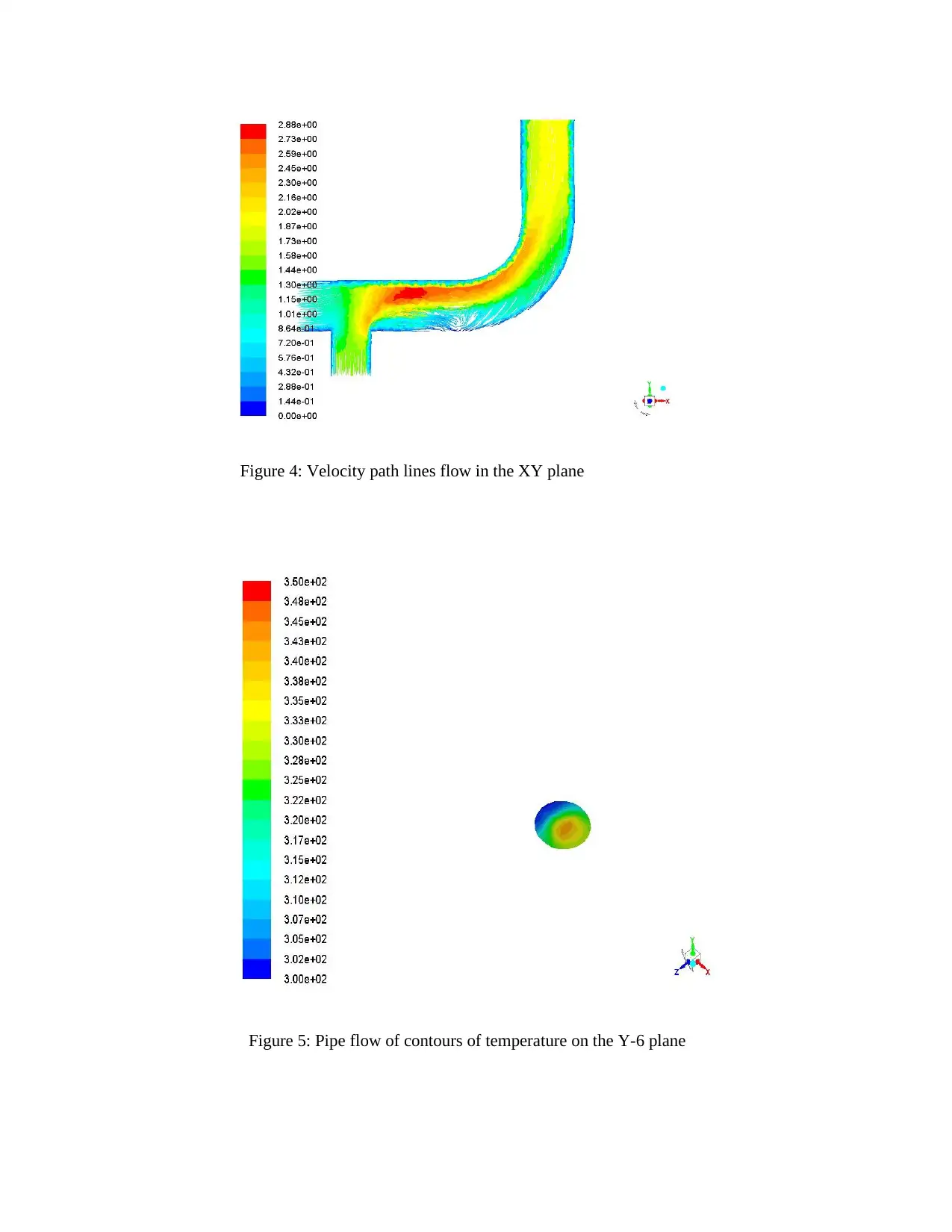
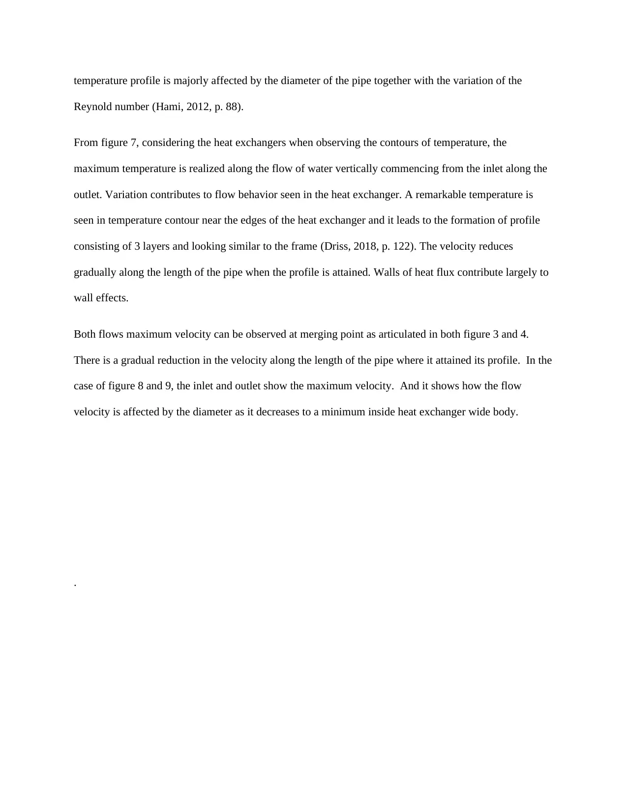
This document explains the use of ANSYS Fluent application for fluid flow simulation in pipe and heat exchanger. It covers the procedure, creating the system for fluid analysis, geometry and modeling, meshing in ANSYS meshing app, and results obtained from velocity and temperature. The document also includes pictures and a bibliography.
tabler-icon-diamond-filled.svg

Contribute Materials

Your contribution can guide someone’s learning journey. Share your documents today.
Document Page
Name of the Student
Name of the Professor
City/State
Date/Month/Year
tabler-icon-diamond-filled.svg

Secure Best Marks with AI Grader

Need help grading? Try our AI Grader for instant feedback on your assignments.
Document Page
Abstract
Introduction to ANSYS Fluent application upon fluid flow simulation in the pipe and heat exchanger.
Part 11 procedure (Heat Exchanger)
Creating the system for fluid analysis (ANSYS Workbench)
Heat exchanger needs to be modeled by a given dimensions provided in the lab note so that ANSTS
FLUENT use in simulating the flow of water can be utilized. To carry out the numerical simulation, you
commence by clicking the ANSYS workbench in the start menu. Inside the toolbox, there is a problem to
be selected and in case the fluid flow is selected then you will be directed to the fluid flow analysis
system. Double clicking of the fluid flow will allow renaming of the analysis as the pipe flow.
In the case of small pipes, at the box left part have to first assign the plane mentioned as the sketching
plane in the outline. To draw the small circle for the pipe inlet, then the Draw circle menu is used in
performing the operation. And it is extruded with dimensions provided. The operation should be
performed to the pipe outlet at the bottom. The name of the body to be changed to the fluid.
Geometry and modeling
Geometry system needs to be created after defining the fluid flow system and this is done by
first, clicking the geometry window twice in the fluent analysis. Then clicking the units' menu to
allow assigning the units to meter. Define the profile to outline the basis of our model and it can
be done by clicking the YZ plane followed by clicking the sketch toolbar (Sidebotham, 2015, p.
55).
From the tree outline, the sketching part is clicked and plane 4 is selected. Ticking the boxes in
the setting toolbox enables the snap model after which major grid spacing is set. In the sketching
point, after clicking the drawing button, begin by drawing the box in a rectangular shape by
Document Page
assigning its dimension menu, then add the box length, depth, and width. The extrude is clicked
to generate the box geometry (Yeoh, 2013, p. 227). The plane mentioned above needs to be
assigned to the sketching plane in the outline in the case of small pipe on the top of the box. The
pipe inlet for a small circle can be drawn by the circle menu. In the case of small pipes at the left
part of the box have to first assign the plane mentioned as the sketching plane in the outline. To draw the
small circle for the pipe inlet, then the Draw circle menu is used in performing the operation. And it is
extruded with dimensions provided. The operation should be performed to the pipe outlet at the bottom.
The name of the body to be changed to the fluid.
Meshing in ANSYS meshing app
The meshing option in the ANSYS workbench system needs to be double-clicked thus the
meshing window appears. In geometry, the large inlet needs to be selected first followed by
clicking the menu on the right. After this, the selection named is created and it is named as
velocity-inlet large (Niyogi, 2009, p. 332).
To allow launching of ANSYS fluent, ok is pressed on the ANSYS launcher after double-
clicking the set up in the ANSYS workbench system. After this, on the navigation menu, the
general is clicked to allow the setting of certain settings for CDF analysis. The materials are
clicked to add certain details; clicking materials>fluid>edit/create>input information. The cell
zone is clicked to allow the setting up of cell zone condition for CDF simulation. Since the outlet
and the inlet have a constant velocity, they are elected immediately after setting the boundary
conditions by clicking the menu.
The setting up of boundary conditions is necessary and it is carried out by selecting it in the
menu followed by electing of the outlet as well as the outlet because their velocity is constant.
Document Page
The inner surface temperature is also constant at 273K. The outlet pressure to be edited and the
pressure of the gauge to be set to zero. After which we go ahead and Run calculation and click
Yes and set 50 to the number of interactions the click to perform the operations or calculate.
Through the results selection, Graphics and Animation are selected > contours are selected>
New surface is clicked> plane is selected> point and normal> coordinates are set. Click on the
contours and filled then choose the plane and click displays to view the results.
Results in Pictures
Figure 1: Contours of pressure in the pipe flow
tabler-icon-diamond-filled.svg

Secure Best Marks with AI Grader

Need help grading? Try our AI Grader for instant feedback on your assignments.
Document Page
Figure 2: Contours of temperature in the pipe flow
Figure 3: Velocity vectors through the pipe flow
Document Page
Figure 4: Velocity path lines flow in the XY plane
Figure 5: Pipe flow of contours of temperature on the Y-6 plane
Document Page
Figure 6: Contours of pressure inside the heat exchanger
Figure 7: Contours of temperature inside the heat exchanger
tabler-icon-diamond-filled.svg

Paraphrase This Document

Need a fresh take? Get an instant paraphrase of this document with our AI Paraphraser
Document Page
Figure 8: Velocity vectors of flow in the heat exchanger
Figure 9: Velocity path lines inside the heat exchanger.
Discussion on results obtained from velocity and temperature
Around the pipe inlet, a variation of temperature is realized when it is inspected and then it goes down
gradually relative to the pipe length until a steady profile is attained near the pipe endpoint. The
Document Page
temperature profile is majorly affected by the diameter of the pipe together with the variation of the
Reynold number (Hami, 2012, p. 88).
From figure 7, considering the heat exchangers when observing the contours of temperature, the
maximum temperature is realized along the flow of water vertically commencing from the inlet along the
outlet. Variation contributes to flow behavior seen in the heat exchanger. A remarkable temperature is
seen in temperature contour near the edges of the heat exchanger and it leads to the formation of profile
consisting of 3 layers and looking similar to the frame (Driss, 2018, p. 122). The velocity reduces
gradually along the length of the pipe when the profile is attained. Walls of heat flux contribute largely to
wall effects.
Both flows maximum velocity can be observed at merging point as articulated in both figure 3 and 4.
There is a gradual reduction in the velocity along the length of the pipe where it attained its profile. In the
case of figure 8 and 9, the inlet and outlet show the maximum velocity. And it shows how the flow
velocity is affected by the diameter as it decreases to a minimum inside heat exchanger wide body.
.
Document Page
Bibliography
Driss, Z., 2018. CFD technique and energy applications. 2 ed. s.l.:Carlton Books.
Hami, A., 2012. Fluid structure interaction and uncertainities. 3 ed. s.l.:Sanoma.
Keler, G., 2010. Engineering analysis with ANSYS software. 3 ed. s.l.:Adventure Works Press.
Niyogi, P., 2009. Introduction to computationsl fluid dynamics. 2 ed. s.l.:OLMA Media Group.
Sidebotham, G., 2015. Heat transfer modelling. 2 ed. s.l.:Media participations.
Yeoh, G., 2013. Multiphase flow analysis usin population balance modelling. 1 ed. s.l.:China Publishing
Company.
chevron_up_icon
1 out of 10
circle_padding
hide_on_mobile
zoom_out_icon
[object Object]

Your All-in-One AI-Powered Toolkit for Academic Success.

Available 24*7 on WhatsApp / Email

[object Object]